A.Hello everyone! Welcome to Benjamin’s blog. As the semester comes to a close, I’m excited to share my journey and the valuable lessons I’ve learned through my participation in the Interaction Lab.
B.Concept and Design: During this semester, I immersed myself in a plethora of action movies. I noticed a recurring plot device that captivated my attention—the tense moment when the main character confronts a time bomb. In these movies, the antagonist typically places a time bomb on a hostage, leaving the protagonist with a limited timeframe to save the day. What intrigued me the most was the pivotal scene where the main character is faced with a critical decision: cutting the correct wire among the three presented. The suspense and anticipation surrounding this moment were incredibly engaging. Inspired by this, I aspired to create a project that could replicate the thrilling experience of defusing a time bomb. However, after discussing my initial concept with Prof. Andy, I realized there were some challenges. Firstly, incorporating Processing into the project proved to be difficult, as the focus was primarily on Arduino. Secondly, realistically simulating the tension and anxiety of a real-time bomb scenario was impractical. Prof. Andy emphasized that the primary goal of the final project should be to provide users with a fun and engaging experience.
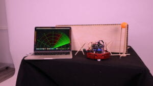
After careful consideration and extensive discussions, I decided to shift my project’s focus to a robotic car. I envisioned a scenario where users would take control of the car and navigate it through a series of obstacles without colliding with them. This idea was divided into two parts: the first part allowed users to observe the obstacles in their path, while the second part concealed both the obstacles and the car’s motion. In this second phase, users had to rely solely on a radar diagram to navigate successfully. The game would end if the radar detected the car.
C. Fabrication and Production: Creating the robotic car presented its own set of challenges. Initially, I had planned to construct a car with four wheels. However, after considering the available power, I realized that supporting four motors would be problematic. To address this, I made the decision to design a car with just two wheels. This adjustment introduced a new challenge—how to effectively control the car. Initially, I explored using a Bluetooth module for control, but the signal proved to be unstable. After numerous attempts and troubleshooting, I ultimately settled on using an IR remote control, which provided a stable and reliable method of operating the car.
To ensure that my project met user expectations, I conducted user tests. Although the project was still in its early stages, I shared the concept with several users. Their feedback was overwhelmingly positive, with many expressing enthusiasm and excitement about the idea. They believed that if I could bring the concept to life, it would be a fantastic experience. Additionally, they provided valuable advice, suggesting that I avoid overexplaining the project and instead focus on providing users with ample room for engagement and exploration.
Following the user tests, I delved deeper into perfecting the robotic car. This involved extensive research, studying various resources, including webpages and YouTube videos, to understand the best practices for coding and programming the IR remote control. It was a challenging task, but with determination and perseverance, I successfully programmed the remote control to effectively maneuver the car. To streamline the setup, I borrowed a platform from Prof. Andy and acquired an L293D motor shield and the necessary wiring from the equipment room. To ensure a stable power supply, I utilized six batteries. Additionally, I incorporated an IR receiver to enable the robotic car to receive and interpret signals from the remote control.
The radar component of the project relied on an ultrasonic sensor and a servo. By attaching the ultrasonic sensor to the servo, I enabled it to rotate at regular intervals, scanning the surroundings. To optimize its functionality, I studied various radar diagrams and made adjustments to the range, setting it to detect objects within a 40-centimeter radius. If the car entered this range, the radar would detect it, triggering the end of the game.
For the second phase of the project, I employed laser cutting techniques to create a specially designed box measuring 60x50x40 cm. This box provided a confined space in which the car could be fully contained, adding an additional layer of challenge and excitement to the game.
To further enhance the overall enjoyment of the experience, I introduced a barrier gate between the two project phases. This barrier gate employed an ultrasonic sensor and a servo. As the car approached the barrier gate, the ultrasonic sensor would detect its presence, causing the barrier to roll up, providing a thrilling and dynamic element to the game.
Curcuit diagram:
Radar:
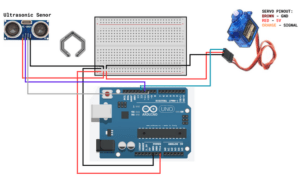
Barrier gate:
Robotic car:
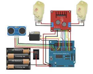
Image:
Videos:
https://drive.google.com/file/d/1IokTioV8uLoX00EyKyfDv2dMNDfxCw3_/view?usp=drive_link
Disassembly
D. Conclusion:In conclusion, my project was an incredible technical undertaking that allowed me to expand my knowledge and skills in both coding and hardware development. Throughout the process, I learned valuable lessons, such as the importance of remaining calm and systematically troubleshooting when encountering problems. I discovered that starting with the most fundamental steps, like checking for loose wires, can often resolve issues. Furthermore, I gained a profound understanding of the disparity between ambition and reality. While I initially had grand aspirations for my project, I quickly realizedthat practical constraints required me to adapt and modify my plans along the way. This flexibility and willingness to adjust proved crucial in achieving a successful outcome.
As a designer, I also learned the significance of empathizing with the users. By putting myself in their shoes and considering their perspective, I was able to make informed decisions that enhanced the engagement and enjoyment of the project. This user-centered approach allowed me to deliver a more fulfilling experience, as I considered the project from a fresh and unbiased standpoint.
Overall, the journey of creating this robotic car project was filled with challenges, learning opportunities, and valuable insights. It pushed me to explore new technologies, problem-solve, and think creatively. I am grateful for the guidance and support from Prof. Andy and the Interaction Lab course, as they provided me with the necessary resources and encouragement to bring my project to fruition.
As I reflect on this semester’s experiences, I feel a great sense of accomplishment and growth. I look forward to applying the knowledge and skills gained from this project to future endeavors, knowing that the lessons learned will continue to shape my approach as a designer and developer. Thank you for joining me on this journey, and I hope you found my project and reflections insightful.
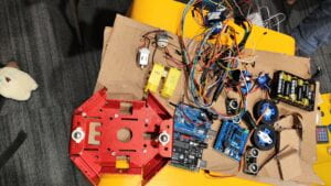
E.Disassembly:
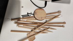
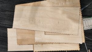
F. Appendix;
Codes:
Radar & Barrier gate:
Arduino codes:
import java.awt.event.KeyEvent; // imports library for reading the data from the serial port
import java.io.IOException;
Serial myPort; // defines Object Serial// defubes variables
String angle=””;
String distance=””;
String data=””;
String noObject;
float pixsDistance;
int iAngle, iDistance;
int index1=0;
int index2=0;
PFont orcFont;
void setup() {
size (1400, 900); // ***CHANGE THIS TO YOUR SCREEN RESOLUTION***
smooth();
myPort = new Serial(this,”/dev/cu.usbmodem1101″, 9600);
myPort.bufferUntil(‘.’); // reads the data from the serial port up to the character ‘.’. So actually it reads this: angle,distance.
}
void draw() {
fill(98,245,31);
// simulating motion blur and slow fade of the moving line
noStroke();
fill(0,4);
rect(0, 0, width, height-height*0.065);
fill(98,245,31); // green color
// calls the functions for drawing the radar
drawRadar();
drawLine();
drawObject();
drawText();
}
void serialEvent (Serial myPort) { // starts reading data from the Serial Port
// reads the data from the Serial Port up to the character ‘.’ and puts it into the String variable “data”.
data = myPort.readStringUntil(‘.’);
data = data.substring(0,data.length()-1);
index1 = data.indexOf(“,”); // find the character ‘,’ and puts it into the variable “index1”
angle= data.substring(0, index1); // read the data from position “0” to position of the variable index1 or thats the value of the angle the Arduino Board sent into the Serial Port
distance= data.substring(index1+1, data.length()); // read the data from position “index1” to the end of the data pr thats the value of the distance
// converts the String variables into Integer
iAngle = int(angle);
iDistance = int(distance);
}
void drawRadar() {
pushMatrix();
translate(width/2,height-height*0.074); // moves the starting coordinats to new location
noFill();
strokeWeight(2);
stroke(98,245,31);
// draws the arc lines
arc(0,0,(width-width*0.0625),(width-width*0.0625),PI,TWO_PI);
arc(0,0,(width-width*0.27),(width-width*0.27),PI,TWO_PI);
arc(0,0,(width-width*0.479),(width-width*0.479),PI,TWO_PI);
arc(0,0,(width-width*0.687),(width-width*0.687),PI,TWO_PI);
// draws the angle lines
line(-width/2,0,width/2,0);
line(0,0,(-width/2)*cos(radians(30)),(-width/2)*sin(radians(30)));
line(0,0,(-width/2)*cos(radians(60)),(-width/2)*sin(radians(60)));
line(0,0,(-width/2)*cos(radians(90)),(-width/2)*sin(radians(90)));
line(0,0,(-width/2)*cos(radians(120)),(-width/2)*sin(radians(120)));
line(0,0,(-width/2)*cos(radians(150)),(-width/2)*sin(radians(150)));
line((-width/2)*cos(radians(30)),0,width/2,0);
popMatrix();
}
void drawObject() {
pushMatrix();
translate(width/2,height-height*0.074); // moves the starting coordinats to new location
strokeWeight(9);
stroke(255,10,10); // red color
pixsDistance = iDistance*((height-height*0.1666)*0.025); // covers the distance from the sensor from cm to pixels
// limiting the range to 40 cms
if(iDistance<40){
// draws the object according to the angle and the distance
line(pixsDistance*cos(radians(iAngle)),-pixsDistance*sin(radians(iAngle)),(width-width*0.505)*cos(radians(iAngle)),-(width-width*0.505)*sin(radians(iAngle)));
}
popMatrix();
}
void drawLine() {
pushMatrix();
strokeWeight(9);
stroke(30,250,60);
translate(width/2,height-height*0.074); // moves the starting coordinats to new location
line(0,0,(height-height*0.12)*cos(radians(iAngle)),-(height-height*0.12)*sin(radians(iAngle))); // draws the line according to the angle
popMatrix();
}
void drawText() { // draws the texts on the screen
pushMatrix();
if(iDistance>30) {
noObject = “Out of Range”;
}
else {
noObject = “In Range”;
}
fill(0,0,0);
noStroke();
rect(0, height-height*0.0648, width, height);
fill(98,245,31);
textSize(25);
text(“10cm”,width-width*0.3854,height-height*0.0833);
text(“20cm”,width-width*0.281,height-height*0.0833);
text(“30cm”,width-width*0.177,height-height*0.0833);
text(“40cm”,width-width*0.0729,height-height*0.0833);
textSize(40);
text(“Ben “, width-width*0.875, height-height*0.0277);
text(“Angle: ” + iAngle +”°”, width-width*0.48, height-height*0.0277);
text(“Distance: “, width-width*0.26, height-height*0.0277);
if(iDistance<40) {
text(” ” + iDistance +” cm”, width-width*0.225, height-height*0.0277);
}
textSize(25);
fill(98,245,60);
translate((width-width*0.4994)+width/2*cos(radians(30)),(height-height*0.0907)-width/2*sin(radians(30)));
rotate(-radians(-60));
text(“30°”,0,0);
resetMatrix();
translate((width-width*0.503)+width/2*cos(radians(60)),(height-height*0.0888)-width/2*sin(radians(60)));
rotate(-radians(-30));
text(“60°”,0,0);
resetMatrix();
translate((width-width*0.507)+width/2*cos(radians(90)),(height-height*0.0833)-width/2*sin(radians(90)));
rotate(radians(0));
text(“90°”,0,0);
resetMatrix();
translate(width-width*0.513+width/2*cos(radians(120)),(height-height*0.07129)-width/2*sin(radians(120)));
rotate(radians(-30));
text(“120°”,0,0);
resetMatrix();
translate((width-width*0.5104)+width/2*cos(radians(150)),(height-height*0.0574)-width/2*sin(radians(150)));
rotate(radians(-60));
text(“150°”,0,0);
popMatrix();
}
Robotic car:
#include <IRremote.h>
long run_car = 0x00FF629D;//Button CH
long back_car = 0x00FFA857;//Button+
long left_car = 0x00FF22DD;//Button<<
long right_car = 0x00FFC23D;//Button>||
long stop_car = 0x00FF02FD;//Button>>|
//==============================
int Left_motor_go=8; //Left motor forward(IN1)
int Left_motor_back=9; //Left motor backward(IN2)
int Right_motor_go=10; // Right motor forward(IN3)
int Right_motor_back=11; // Right motor backward(IN4)
void setup()
{
pinMode(Left_motor_go,OUTPUT); // PIN 8 (PWM)
pinMode(Left_motor_back,OUTPUT); // PIN 9 (PWM)
pinMode(Right_motor_go,OUTPUT);// PIN 10 (PWM)
pinMode(Right_motor_back,OUTPUT);// PIN 11 (PWM)
pinMode(13, OUTPUT);
Serial.begin(9600);
irrecv.enableIRIn(); // Start the receiver
}
void run()
{
digitalWrite(Right_motor_go,HIGH);
digitalWrite(Right_motor_back,LOW);
analogWrite(Right_motor_go,100);
//analogWrite(Right_motor_back,0);
digitalWrite(Left_motor_go,LOW);
digitalWrite(Left_motor_back,HIGH);
//analogWrite(Left_motor_go,0);
analogWrite(Left_motor_back,100);
//delay(time * 100);
}
void brake()
{
digitalWrite(Right_motor_go,LOW);
digitalWrite(Right_motor_back,LOW);
digitalWrite(Left_motor_go,LOW);
digitalWrite(Left_motor_back,LOW);
//delay(time * 100);
}
void left()
digitalWrite(Right_motor_go,HIGH);
digitalWrite(Right_motor_back,LOW);
//analogWrite(Right_motor_go,200);
//analogWrite(Right_motor_back,0);
digitalWrite(Left_motor_go,LOW);
digitalWrite(Left_motor_back,LOW);
//analogWrite(Left_motor_go,0);
//analogWrite(Left_motor_back,0);
//delay(time * 10