RIC week 8 exprimentation

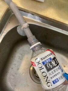
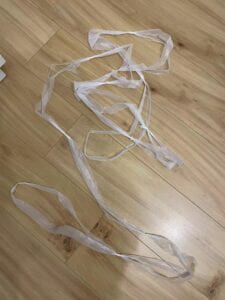
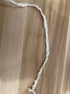
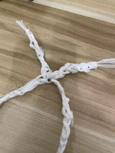
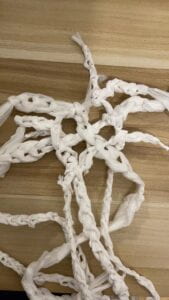
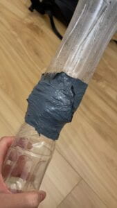
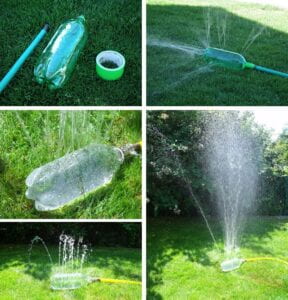
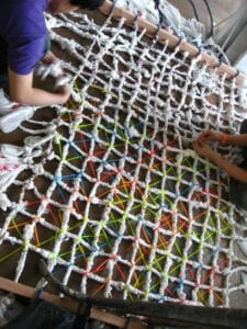
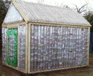
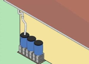
We opted to build a water collection system for Garden No. 2 after reviewing our material tests from the previous week. This system will have a gutter that runs along one side of the building’s roof and is slightly inclined downwards to allow water to flow out and into a collection bucket below. We considered using water bottles as a tube running down the side of the building, but opted against it because PET bottles are already recycled. We also experimented with weaving plastic bags into a net to filter out large waste from the water, but this proved too time consuming and ineffective for smaller debris.

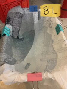
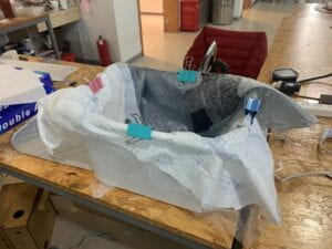
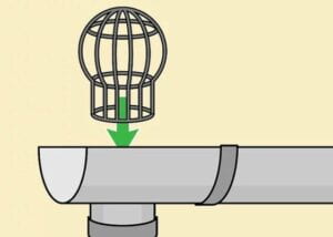
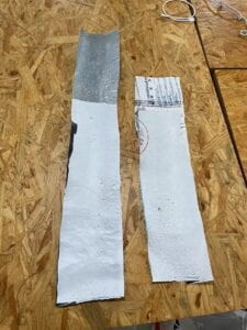
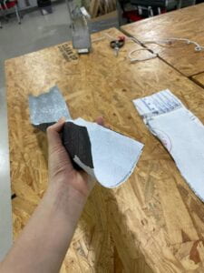
We eventually decided to use fused layers of plastic bags to create sturdy sheets that can be easily shaped. We first used this technique to make a fish pond lining, but we discovered that layering the bags even more gave it more potential for a more useful creation. As a result, we decided to use this material to make U-shaped gutters that would be hung on the side of the roof, as well as to poke holes in it to create a filter for the collection bucket.
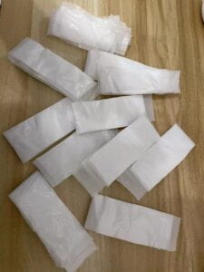
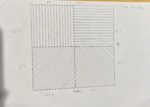
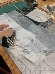
We experimented with various types of bags and discovered that shipping packaging bags were the easiest to fuse and the strongest when layered. We used an iron to fuse the bags into a single large layer and then folded them to make the sheets. The resulting material is waterproof and strong while remaining pliable, allowing us to shape it into a U shape to hold water. It is lightweight, which makes it easy to adhere to the roof, but it is also prone to misshaping due to wind or rain. To counteract this, we’ll need to use sturdier plastic to keep it attached to the building and maintain its shape.

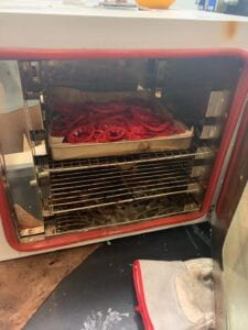
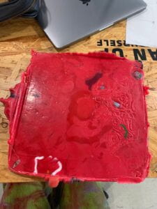
We melted polypropylene bottle caps into a 2cm thick board at 230 degrees Celsius and let it cool overnight in the press to make this sturdier material. We will then use a laser cutter to cut them into hanger shapes that can be screwed into the structure and keep the gutter in place. This is a strong material, but it is more difficult to duplicate than fused plastic. Wire will be used to hold the U shape on the bottom of the gutter, and we’ll need to figure out a secure way to screw the plastic into the building.


RIC week 7 Experimentation

Pool trap

We pressed plastic bags together into a huge sheet to build a waterproof tarp to line a pool. To melt different bags into a single sheet of plastic, we employed both hand-held irons and a heat press. We tested various types of plastic bags and discovered that soft and elastic bags easily tore and did not melt well. Plastic bags used for shipping packaging, on the other hand, proved to be the most effective. We were eventually able to make a modest prototype with the tarp lining a bucket of water. It successfully held the water, demonstrating that it was leakproof. Going on, we shall collect plastic shipping bags in order to make a sheet largely formed of that material, which will result in a more seamless sheet.


Sprinkler head

To make a sprinkler head for easier plant watering, we drilled holes in a plastic bottle so the water would spray more strongly. Our experiment worked, but we need to make the holes slightly larger to allow more water to get through and find a way to properly connect the faucet/hose to the bottle. We’ll probably have to use tape to secure it, which won’t be easy to remove or serve as a long-term solution. To make it more long-lasting, we’d have to utilize a screw top on both ends, which would be difficult to build.


Filter Net

We used plastic bags to weave a net to keep leaves, branches, and other debris out of a rainwater collection system. We cut the bags into loops, knotted the loops together, and then crocheted the loops into a braid. We linked many of these braids to make a net that may trap heavier debris. We were able to achieve varying braid thicknesses by cutting the loops into different widths. However, the braids’ varying thickness and tightness made weaving them together problematic. To make assembly easier in the future, we should cut more consistent loops and weave them looser.

Water Tube

We made a tube last week by cutting slots in the bottoms of plastic bottles and interlocking them together. We used a hairdryer on plastic shipping wrapping wrapped around the seam to seal the attachment and make it leakproof. The heat caused the slits in the bottle to distort as the plastic around the bottles shrank to making the attachment more secure. This resulted in sharp edges that sliced into the plastic, causing leaks in the bond. This does not appear to be a viable option because boiling the bottles will twist them into unfavorable shapes. To avoid the heat, we would most likely need to use strong tape.

Interaction Lab recitation 8 documentation

Exercise 1: Make a Processing Etch-A-Sketch

etch-a-sketch

Arduino code:

void setup() {
Serial.begin(9600);
}

void loop() {
// to send values to Processing assign the values you want to send
//this is an example
int sensor1 = analogRead(A0);
int sensor2 = analogRead(A1);
//int sensor3 = analogRead(A2);

// send the values keeping this format
Serial.print(sensor1);
Serial.print(“,”); // put comma between sensor values
Serial.print(sensor2);
//Serial.print(“,”); // put comma between sensor values
// Serial.print(sensor3);
Serial.println(); // add linefeed after sending the last sensor value

// too fast communication might cause some latency in Processing
// this delay resolves the issue.
delay(100);

// end of example sending values
}

Processing code:

import processing.serial.*;
float x, y, px, py;

int NUM_OF_VALUES = 2; /** YOU MUST CHANGE THIS ACCORDING TO YOUR PROJECT **/
int sensorValues[]; /** this array stores values from Arduino **/

String myString = null;
Serial myPort;

void setup() {
size(500, 500);
background(255);
setupSerial();
if (sensorValues[0]!=0 && sensorValues[1] !=0) {
x=map(sensorValues[0], 0, 1023, 0, width);
y=map(sensorValues[1], 0, 1023, 0, height);
px=x;
py=y;
}

stroke(0, 0, 200);
strokeWeight(3);

line(x, y, px, py);
}

void draw() {
//background(255);
getSerialData();
//printArray(sensorValues);

// use the values like this!
// sensorValues[0]

// add your code
if( px != 0 && py !=0 ){
line(x, y, px, py);
}
px=x;
py=y;
x=map(sensorValues[0], 0, 1023, 0, width);
y=map(sensorValues[1], 0, 1023, 0, height);
fill(200, 0, 0);
//ellipse(x,y,5,5);
stroke(0, 0, 200);
strokeWeight(3);

//
}


void setupSerial() {
printArray(Serial.list());
myPort = new Serial(this, Serial.list()[3], 9600);
// WARNING!
// You will definitely get an error here.
// Change the PORT_INDEX to 0 and try running it again.
// And then, check the list of the ports,
// find the port “/dev/cu.usbmodem—-” or “/dev/tty.usbmodem—-”
// and replace PORT_INDEX above with the index number of the port.

myPort.clear();
// Throw out the first reading,
// in case we started reading in the middle of a string from the sender.
myString = myPort.readStringUntil( 10 ); // 10 = ‘\n’ Linefeed in ASCII
myString = null;

sensorValues = new int[NUM_OF_VALUES];
}


void getSerialData() {
while (myPort.available() > 0) {
myString = myPort.readStringUntil( 10 ); // 10 = ‘\n’ Linefeed in ASCII
if (myString != null) {
String[] serialInArray = split(trim(myString), “,”);
if (serialInArray.length == NUM_OF_VALUES) {
for (int i=0; i<serialInArray.length; i++) {
sensorValues[i] = int(serialInArray[i]);
}
}
}
}
}

At first I encounterd that a line would formed out of no where. Then I solved it by adding a new line of code if (sensorValues[0]!=0 && sensorValues[1] !=0)  into the setup. And if( px != 0 && py !=0 ){
line(x, y, px, py); This makes it only draw when the sensor values are not zero.

Exercise 2:

Work with a partner to write a Processing sketch in which a ball bounces from left to right on the screen. (You can use the fullScreen() function, instead of size(), to make the Processing window occupy the full dimensions of your screen.) Send values from Processing to Arduino based on the position of the bouncing ball. These values should somehow give an indication of when the ball hits the edge of the screen. Then, make a circuit with your Arduino and 2 servo motors. The corresponding Arduino code should read the serial values from Processing and translate them into movements, through the appropriate servo motor, as if they are hitting the ball back and forth.  See the video below for reference. 

After using tape 


Exercise 2:

Arduino:

// IMA NYU Shanghai
// Interaction Lab

/**
  This example is to send multiple values from Processing to Arduino.
  You can find the Processing example file in the same folder which works with this Arduino file.
 **/

#define NUM_OF_VALUES_FROM_PROCESSING 3    /** YOU MUST CHANGE THIS ACCORDING TO YOUR PROJECT **/
#include <Servo.h> 


/** DO NOT REMOVE THESE **/
int tempValue = 0;
int valueIndex = 0;
int angle = 0;

/* This is the array of values storing the data from Processing. */
int processing_values[NUM_OF_VALUES_FROM_PROCESSING];

Servo L,R;
void setup() {
  Serial.begin(9600);
  L.attach(8);
  R.attach(7);
  pinMode(13, OUTPUT);
  L.write(0); 
  R.write(0); 
}

void loop() {
  getSerialData();

  // add your code here using elements in the values array

  //this is an example connecting a buzzer to pin 8
  
    if (processing_values[0] == 1) {
      moveServo(L);
      digitalWrite(13, HIGH);
    }
     else if (processing_values[1] == 1) {
      moveServo(R);
      digitalWrite(13, HIGH);
    }else{
    digitalWrite(13, LOW);
    }


}

void moveServo(Servo servo_test){                               
    servo_test.write(90);
    delay(1);
    servo_test.write(-90);                       
}
//receive serial data from Processing
void getSerialData() {
  while (Serial.available()) {
    char c = Serial.read();
    //switch - case checks the value of the variable in the switch function
    //in this case, the char c, then runs one of the cases that fit the value of the variable
    //for more information, visit the reference page: https://www.arduino.cc/en/Reference/SwitchCase
    switch (c) {
      //if the char c from Processing is a number between 0 and 9
      case '0'...'9':
        //save the value of char c to tempValue
        //but simultaneously rearrange the existing values saved in tempValue
        //for the digits received through char c to remain coherent
        //if this does not make sense and would like to know more, send an email to me!
        tempValue = tempValue * 10 + c - '0';
        break;
      //if the char c from Processing is a comma
      //indicating that the following values of char c is for the next element in the values array
      case ',':
        processing_values[valueIndex] = tempValue;
        //reset tempValue value
        tempValue = 0;
        //increment valuesIndex by 1
        valueIndex++;
        break;
      //if the char c from Processing is character 'n'
      //which signals that it is the end of data
      case '\n':
        //save the tempValue
        //this will b the last element in the values array
        processing_values[valueIndex] = tempValue;
        //reset tempValue and valueIndex values
        //to clear out the values array for the next round of readings from Processing
        tempValue = 0;
        valueIndex = 0;
        break;
    }
  }
}


Processing:

// IMA NYU Shanghai
// Interaction Lab

/**
 * This example is to send multiple values from Processing to Arduino.
 * You can find the arduino example file in the same folder which works with this Processing file.
 **/

import processing.serial.*;

int NUM_OF_VALUES_FROM_PROCESSING = 3;  /** YOU MUST CHANGE THIS ACCORDING TO YOUR PROJECT **/
int processing_values[] = new int[NUM_OF_VALUES_FROM_PROCESSING]; /** this array stores values you might want to send to Arduino **/

Serial myPort;
String myString;
float mov=20;
float horipos;
float rad=100;

void setup() {
  fullScreen();

  background(0);
  setupSerial();
  horipos=width/2;
}

void draw() {
  background(0);
  horipos+=mov;
  if(horipos<=0){
    mov=-mov;
    processing_values[0] = 1;
  }
  if(horipos>rad &&horipos<width-rad){
    processing_values[0] = 0;
    processing_values[1] = 0;
  }
  if(horipos>=width){
    mov=-mov;
    processing_values[1] = 1;
  }
  circle(horipos,height/2,rad);
  sendSerialData();


}

void setupSerial() {
  printArray(Serial.list());
  myPort = new Serial(this, Serial.list()[0], 9600);
  // WARNING!
  // You will definitely get an error here.
  // Change the PORT_INDEX to 0 and try running it again.
  // And then, check the list of the ports,
  // find the port "/dev/cu.usbmodem----" or "/dev/tty.usbmodem----" 
  // and replace PORT_INDEX above with the index number of the port.

  myPort.clear();
  // Throw out the first reading,
  // in case we started reading in the middle of a string from the sender.
  myString = myPort.readStringUntil( 10 );  // 10 = '\n'  Linefeed in ASCII
  myString = null;

}

void sendSerialData() {
  String data = "";
  for (int i=0; i<processing_values.length; i++) {
    data += processing_values[i];
    //if i is less than the index number of the last element in the values array
    if (i < processing_values.length-1) {
      data += ","; // add splitter character "," between each values element
    } 
    //if it is the last element in the values array
    else {
      data += "\n"; // add the end of data character linefeed "\n"
    }
    
  }
  //write to Arduino
  myPort.write(data);
  print(data); // this prints to the console the values going to arduino 
  
}

Homework:

Arduino:

// IMA NYU Shanghai
// Interaction Lab
// For sending multiple values from Arduino to Processing
int button1 = 5;
int button2 = 6;
int buttonState1 = LOW;
int previousState1 = LOW;
int buttonState2 = LOW;
int previousState2 = LOW;
//button state : on and off low--off  high--on
int counter1 = 0;
int counter2 = 0;
// how many times the button been pressed
//int state1, state2;;

long time = 0;         // the last time the output pin was toggled
long debounce = 200;   // the debounce time, increase if the output flickers

void setup() {
  Serial.begin(9600);
  pinMode(button1, INPUT);
  pinMode(button2, INPUT);

}

void loop() {
  // to send values to Processing assign the values you want to send
  //this is an example
  int buttonState1 = digitalRead(button1);// digital read here for on and off, analogread is for potentiameter
  int buttonState2 = digitalRead(button2);
  //  int sensor3 = analogRead(A2);

  //how many times button1 pressed
  if (buttonState1 != previousState1 && millis() - time > debounce) {
    if (buttonState1 == HIGH) {
      counter1++;
      time = millis();
    }
  }
  previousState1 = buttonState1;

  
  //how many times button2 pressed
  if (buttonState2 != previousState2 && millis() - time > debounce) {
    if (buttonState2 == HIGH) {
      counter2++;
      time = millis();
    }
  }
  previousState2 = buttonState2;


  // send the values keeping this format
  Serial.print(counter1);
  Serial.print(",");  // put comma between sensor values
  Serial.print(counter2);
  //Serial.print(",");  // put comma between sensor values
  //Serial.print(sensor3);
  Serial.println(); // add linefeed after sending the last sensor value

  // too fast communication might cause some latency in Processing
  // this delay resolves the issue.
  delay(100);

  // end of example sending values
}

Processing:

// IMA NYU Shanghai
// Interaction Lab
// For receiving multiple values from Arduino to Processing

/*
 * Based on the readStringUntil() example by Tom Igoe
 * https://processing.org/reference/libraries/serial/Serial_readStringUntil_.html
 */

import processing.serial.*;


int NUM_OF_VALUES_FROM_ARDUINO = 2;   /** YOU MUST CHANGE THIS ACCORDING TO YOUR PROJECT **/
int buttonValues[];      /** this array stores values from Arduino **/

String myString = null;
Serial myPort;

void setup() {
  size(500, 500);
  background(0);
  setupSerial();
}

void draw() {
  getSerialData();
  println(buttonValues);


  if ((buttonValues[0]%2 == 1)&&(buttonValues[1]%2 == 0)) {
    background(0);
   // star(width*0.3, height*0.3, 30, 70, 5);
    pushMatrix();
  translate( width*0.3, height*0.3);
  rotate(frameCount / 200.0);
  star(0, 0, 30, 70, 5);
  popMatrix();
  } 
  
   if ((buttonValues[0]%2 == 0)&&(buttonValues[1]%2 == 1)) {
     background(0);
    //star(width*0.7, height*0.7, 80, 100, 40);
     pushMatrix();
  translate( width*0.7, height*0.7);
  rotate(frameCount / 200.0);
  star(0, 0, 80, 100, 40);
  popMatrix();
  }

  if ((buttonValues[0]%2 == 1) &&(buttonValues[1]%2 == 1)) {
    background(0);
    //star(width*0.7, height*0.7, 80, 100, 40);
    pushMatrix();
  translate( width*0.7, height*0.7);
  rotate(frameCount / 200.0);
  star(0, 0, 80, 100, 40);
  popMatrix();
   
    //star(width*0.3, height*0.3, 30, 70, 5);
    pushMatrix();
  translate( width*0.3, height*0.3);
  rotate(frameCount / 200.0);
  star(0, 0, 30, 70, 5);
  popMatrix();
  }
  
  if ((buttonValues[0]%2 == 0) &&(buttonValues[1]%2 == 0)) {
   background(0);
  } 


  //pushMatrix();
  //translate( width*0.3, height*0.3);
  //rotate(frameCount / 200.0);
  //star(0, 0, 30, 70, 5);

  //popMatrix();

}


void setupSerial() {
  printArray(Serial.list());
  myPort = new Serial(this, Serial.list()[ 1 ], 9600);
  // WARNING!
  // You will definitely get an error here.
  // Change the PORT_INDEX to 0 and try running it again.
  // And then, check the list of the ports,
  // find the port "/dev/cu.usbmodem----" or "/dev/tty.usbmodem----"
  // and replace PORT_INDEX above with the index number of the port.

  myPort.clear();
  // Throw out the first reading,
  // in case we started reading in the middle of a string from the sender.
  myString = myPort.readStringUntil( 10 );  // 10 = '\n'  Linefeed in ASCII
  myString = null;

  buttonValues = new int[NUM_OF_VALUES_FROM_ARDUINO];
}

void getSerialData() {
  while (myPort.available() > 0) {
    myString = myPort.readStringUntil( 10 ); // 10 = '\n'  Linefeed in ASCII
    if (myString != null) {
      String[] serialInArray = split(trim(myString), ",");
      if (serialInArray.length == NUM_OF_VALUES_FROM_ARDUINO) {
        for (int i=0; i<serialInArray.length; i++) {
          buttonValues[i] = int(serialInArray[i]);
        }
      }
    }
  }
}

void star(float x, float y, float radius1, float radius2, int npoints) {
  float angle = TWO_PI / npoints;
  float halfAngle = angle/2.0;
  beginShape();
  for (float a = 0; a < TWO_PI; a += angle) {
    float sx = x + cos(a) * radius2;
    float sy = y + sin(a) * radius2;
    vertex(sx, sy);
    sx = x + cos(a+halfAngle) * radius1;
    sy = y + sin(a+halfAngle) * radius1;
    vertex(sx, sy);
  }
  endShape(CLOSE);
}


Interaction Lab final project step 2

3 ideas

First:

How to Play the No Internet Google Chrome Dinosaur Game - Both Online and Offline

(Source:https://images.app.goo.gl/tEZWfcpvGQeZkFGc7)

As shown above, I want to create a similar game using processing. I will connect a sound sensor that captures the human voice. People can make the dragon jump by raising their voices. 

Second:

I want to draw a little boy using processing and that he is trying to move away from raindrops. Below is a prototype video. The red square represents the little boy and the black squares represent raindrops. Finally, I will add a switch using Arduino to control the moving direction of the little boy.

Third:

A ping pong game where there will involve two players.

Each use a controller to punch the ping pong ball.


Interaction Lab Recitation 7: Functions and Arrays blog post

Recitation 7: Functions and Arrays

Part 1: Grid Pattern

Code:

int instances=100;
float[] move = new float[100];
float [] xPos= new float [instances];
float [] yPos= new float[instances];
color [] cL=new color[instances];

void shapeX (float x, float y, color c) {
fill (c);
circle (x, y, 20);
fill (c/2);
rectMode (CENTER);
square (x, y, 30);
fill (c/4);

}
void setup() {
size (600, 600);
background (0);
for (int i=0; i<instances; i++) {
xPos[i]=(random(0, 600));
yPos[i]=(random(0, 600));
cL[i]=color (random(0, 255), random (0, 255), random (0, 255));
move[i]=(random(5));
}
noStroke();
}
void draw() {
background (0);
for (int i=0; i<instances; i++) {
shapeX (xPos[i], yPos[i], cL[i]);
if ((xPos[i] + move[i] > 600)||(xPos[i] + move[i] < 0)) {
move[i]=-move[i];
}
xPos[i] = xPos[i]+move[i];
}
}

  • Q1: In the reading “Art, Interaction and Engagement” by Ernest Edmonds, he identifies four situations in an interactive artwork: ‘Static’, ‘Dynamic-Passive’, ‘Dynamic-Interactive’ and ‘Dynamic-Interactive(Varying)’. From the exercise you did today which situations you identify in every part you executed? Explain.

Today’s works are both static artworks, in my opinion. Because the patterns are self-moving and unaffected by the context or the user’s actions.

  • Q2: What is the benefit of using arrays? How might you use arrays in a potential project?

The advantage of utilizing arrays, in my opinion, is that they may efficiently represent several data types with a single object. The data inside the array may be easily created with the help of the for loop, which is really useful. It’s also a lot easier to access data from an array by calling its index.

Interaction lab recitation 6 blog post

Recitation 6: Processing Animation

Documentation

Upload the screen recording (video) of your interactive animation along with your code (copy-as-HTML) to the documentation blog. Write some comments about what you learned during this recitation, for example, list the most interesting functions you used or what you struggled with. Be thorough so that you can refer to these notes in the future.

comments: I learned how to use the mouse to interact. By using mouse position we can change the graph accordingly.

void setup() {
size(600, 600);
noStroke();
colorMode(HSB, 360, 100, 100);
}

void draw() {
background(204);
fill(0, 100, 200);
if ((mouseX <= 300) && (mouseY <= 300)) {
rect(0, 0, 300, 300); // Upper-left
} else if ((mouseX <= 300) && (mouseY > 300)) {
rect(0, 300, 300, 300); // Lower-left
} else if ((mouseX > 300) && (mouseY <= 300)) {
rect(300, 0, 300, 300); // Upper-right
} else {
rect(300, 300, 300, 300); // Lower-right
}
}

Additional homework:

Step 1

Create a Processing sketch with a circle or square at the center of the screen. Your canvas size should be 600 x 600.

Step 2

Next, modify that Processing sketch so that the circle or square periodically expands and contracts, like the circle in this gif.

Step 3

Then, modify the Processing sketch so that the outline changes color smoothly, as seen in the gif below. HINT: set the colorMode() to HSB.


Step 4:

Code:

float x;
float y;
float a;
float b;
float aspeed=5;
float bspeed=5;
void setup(){
size(600,600);
colorMode(HSB, 360, 100, 100);
x=width/2;
y=height/2;
a=width/2;
b=height/2;
}

void draw(){
background(360);
strokeWeight(20);
ellipse(x,y,a,b);
stroke(a,100,100);
x=map(mouseX,0,600,a/2+10,width-a/2-10);
y=map(mouseY,0,600,b/2+10,height-b/2-10);
a=a-aspeed;
b=b-bspeed;
if (a>width-220|| a<0+120){
aspeed=-aspeed;
}
if (b>height-220||b<0+120){
bspeed=-bspeed;
}

}

Interaction lab final project step 1 research

PREPARATORY RESEARCH AND ANALYSIS

For this assignment, you will compose a blog post in preparation for your final project. Write a narrative of 3 to 4 paragraphs keeping in mind the following items:   
A. Read “Art, Interaction and Engagement” by Ernest Edmonds.

This paper examines the evolution of frameworks for thinking about and discussing interactive art in the context of my personal experience over the last four decades. It follows a multitude of directions, beginning with a simple direct concept of interaction and progressing to communication between individuals via art systems and, more recently, interactive art for long-term involvement. The frameworks are made up of an evolving set of notions that span numerous dimensions and evolve in tandem with the practice of interactive art.

“I have considered just three kinds of engagement. Let’s call them • Attracting

  • Sustaining • Relating” (Edmonds)

According to Edmonds, “ Each action leads to a response that, in turn, encourages or enables another action” (7). This kind of interaction can provide a longer engagement and have a longer-time influence. It was like in the communication, each turn is built on one another, and the conversation may get better and deeper.  

  1. Research at least two new interactive projects that serve as inspiration for your Final Project. Find projects that align with what you think a successful interactive experience is. You are strongly encouraged to consider interactive experiences drawn from a variety of sources, media, materials, formats, etc. Discuss why you chose these specific projects, what aspects you think are successful, and how they will inform your work. 

First:


I chose this because this project is for everyone to interact with. Anyone can use this to show their creativity. The installation is easy to interact with and the effect is spontaneous. I think it was a really successful project because people can play with lights in a fun, interesting, simple way. This project inspired me to create something that can serve a broader audience. And hopefully in a simple and fun way. I noticed his entire production process took two months, and he had a crew with financial assistance. As a result, for my project, I may want to construct something little. Because I only have myself and not enough money.

https://youtu.be/_j5Cqc82Gag

Second:

The Dinosaur Game (also known as the Chrome Dino) is a built-in browser game in the Google Chrome web browser.The player guides a pixelated Tyrannosaurus rex across a side-scrolling landscape, avoiding obstacles to achieve a higher score. The game was created by Sebastien Gabriel in 2014, and is intended to be accessed by hitting the spacebar when Google Chrome is offline.(Wikipedia)

The Dinosaur game, commonly known as the chrome dino, was my second source of inspiration. It shows when your device is not connected to the internet. This is something simple and enjoyable that I choose. It displays when my gadget is not connected to wifi or is offline. It keeps me entertained while I’m waiting to reconnect to the internet. I was considering making something more interactive by using sensors and possibly adding other players. The Dino can move up and down in response to the player’s movements. Increasing the number of players would likewise increase the number of interactions. It may then become a competition.

C. In your own words, explain what contributes to a successful interactive 
experience based on your initial definition of interaction from the group research project and your experience developing and executing your midterm project. Support your explanation with the analysis of the projects you researched in point B, as well as by citing references from the reading by Ernest Edmonds, other readings this semester, and artists or online articles you have read. 


My previous definition of interaction was as follows. Interaction is a mutual and reciprocal conversation that involves two or more individuals on both sides. When one side does specific activities, the other side can detect those actions and respond, letting the first know that he is being understood and providing feedback. In this previous definition, I believe I identify with the frame of “action and response.” So, using this criteria, I created an interactive design for our midterm project. We created a robot type of installation that responds to users based on their actions and what they offer the robot. This is clearly an example of the “action and response” However, to begin with, the interaction should be more comprehensive than a one-round “action and response” , with each turn of the “action and response” building on the previous one and creating a deeper conversation by having more interaction between the two sides. “Each action results in a response, which in turn encourages or permits another action,” Edmonds writes (7). This type of connection can result in a lengthier engagement and a longer-term impact. It seemed as if each turn in the conversation was built on the previous one, and the conversation could get better and deeper as a result. Furthermore, the interaction might take place at the same time. It may or may not have the chronological order 


Interaction lab recitation documentation blog post 5


A Square Divided Horizontally and Vertically into Four Equal Parts, Each with a Different Direction of Alternating Parallel Bands of Lines 1982 Sol LeWitt 1928-2007 Purchased 1984 http://www.tate.org.uk/art/work/P77013

Sol LeWitt, A Square Divided Horizontally and Vertically into Four Equal Parts, Each with a Different Direction of Alternating

Found this motif by clicking the link on interaction lab recitation website.
Really like the diagram and thought it would be easier to draw on processing by drawing four rectangle and split equally and draw 15 lines in each.

My rough sketch 

my code:

int s = 20;
strokeWeight(4);
size(600,600);
rect(0,0, width/2,height/2);
rect(width/2,0, width/2,height/2);
rect(0,height/2, width/2,height/2);
rect(width/2,height/2, width/2,height/2);

line(s,0,s,width/2);
line(s*2,0,s*2,width/2);
line(s*3,0,s*3,width/2);
line(s*4,0,s*4,width/2);
line(s*5,0,s*5,width/2);
line(s*6,0,s*6,width/2);
line(s*7,0,s*7,width/2);
line(s*8,0,s*8,width/2);
line(s*9,0,s*9,width/2);
line(s*10,0,s*10,width/2);
line(s*11,0,s*11,width/2);
line(s*12,0,s*12,width/2);
line(s*13,0,s*13,width/2);
line(s*14,0,s*14,width/2);

line(width/2,s,width,s);
line(width/2,s*2,width,s*2);
line(width/2,s*3,width,s*3);
line(width/2,s*4,width,s*4);
line(width/2,s*5,width,s*5);
line(width/2,s*6,width,s*6);
line(width/2,s*7,width,s*7);
line(width/2,s*8,width,s*8);
line(width/2,s*9,width,s*9);
line(width/2,s*10,width,s*10);
line(width/2,s*11,width,s*11);
line(width/2,s*12,width,s*12);
line(width/2,s*13,width,s*13);
line(width/2,s*14,width,s*14);

line(0,height/2 + s,s,width/2);
line(0,height/2 + s*2,s*2,width/2);
line(0,height/2 + s*3,s*3,width/2);
line(0,height/2 + s*4,s*4,width/2);
line(0,height/2 + s*5,s*5,width/2);
line(0,height/2 + s*6,s*6,width/2);
line(0,height/2 + s*7,s*7,width/2);
line(0,height/2 + s*8,s*8,width/2);
line(0,height/2 + s*9,s*9,width/2);
line(0,height/2 + s*10,s*10,width/2);
line(0,height/2 + s*11,s*11,width/2);
line(0,height/2 + s*12,s*12,width/2);
line(0,height/2 + s*13,s*13,width/2);
line(0,height/2 + s*14,s*14,width/2);
line(0,height/2 + s*15,s*15,width/2);

line(s,height,width/2,height/2 + s);
line(s*2,height,width/2,height/2 + s*2);
line(s*3,height,width/2,height/2 + s*3);
line(s*4,height,width/2,height/2 + s*4);
line(s*5,height,width/2,height/2 + s*5);
line(s*6,height,width/2,height/2 + s*6);
line(s*7,height,width/2,height/2 + s*7);
line(s*8,height,width/2,height/2 + s*8);
line(s*9,height,width/2,height/2 + s*9);
line(s*10,height,width/2,height/2 + s*10);
line(s*11,height,width/2,height/2 + s*11);
line(s*12,height,width/2,height/2 + s*12);
line(s*13,height,width/2,height/2 + s*13);
line(s*14,height,width/2,height/2 + s*14);
line(s*15,height,width/2,height/2 + s*15);

line(width/2,height/2,width, height);
line(width/2+s,height/2,width+s, height);
line(width/2+s*2,height/2,width+s*2, height);
line(width/2+s*3,height/2,width+s*3, height);
line(width/2+s*4,height/2,width+s*4, height);
line(width/2+s*5,height/2,width+s*5, height);
line(width/2+s*6,height/2,width+s*6, height);
line(width/2+s*7,height/2,width+s*7, height);
line(width/2+s*8,height/2,width+s*8, height);
line(width/2+s*9,height/2,width+s*9, height);
line(width/2+s*10,height/2,width+s*10, height);
line(width/2+s*11,height/2,width+s*11, height);
line(width/2+s*12,height/2,width+s*12, height);
line(width/2+s*13,height/2,width+s*13, height);
line(width/2+s*14,height/2,width+s*14, height);
line(width/2+s*15,height/2,width+s*15, height);

line(width/2,height/2 + s, width – s, height);
line(width/2,height/2 + s*2, width – s*2, height);
line(width/2,height/2 + s*3, width – s*3, height);
line(width/2,height/2 + s*4, width – s*4, height);
line(width/2,height/2 + s*5, width – s*5, height);
line(width/2,height/2 + s*6, width – s*6, height);
line(width/2,height/2 + s*7, width – s*7, height);
line(width/2,height/2 + s*8, width – s*8, height);
line(width/2,height/2 + s*9, width – s*9, height);
line(width/2,height/2 + s*10, width – s*10, height);
line(width/2,height/2 + s*11, width – s*11, height);
line(width/2,height/2 + s*12, width – s*12, height);
line(width/2,height/2 + s*13, width – s*13, height);
line(width/2,height/2 + s*14, width – s*14, height);
line(width/2,height/2 + s*15, width – s*15, height);

MY SKETCH ON PROCESSING

Interaction lab midterm project individual reflection

Seeing your sound by Angel & Amber -Marcela

  1. CONTEXT AND SIGNIFICANCE

My previous midterm group project was something that shows the interaction between human and machines. Using strings to show the connections between them and his the transformation of emotions are formed. People provide instructions, which it receives and acts upon, triggering my understanding and definition of interaction: two characters communicate with each other, and both have reactions to each other depending on their communication, creating a loop. As a consequence of this research, I’ve decided to make a voice-activated sensor light that can receive people’s instructions and is helpful in daily life.We improved our idea even further to make it more interactive, which means that not only will the light turn on when there is a sound, but it will also change colors according on the varying volumes of individuals supplying the light. It is unique to our project since it is built specifically for deaf impaired persons. It has unique significance for this target group since deaf individuals cannot hear sound or music, thus they may “hear”  their own voice by looking at the various colors in the light.

  1. CONCEPTION AND DESIGN:

In what ways did your understanding of how your users were going to interact with your project inform certain design decisions you made? Account for several such decisions. In addition, what form, material or elements did you use? What criteria did you use to select those materials? Why was it/were they best suited to your project purpose, more than any other one/s? What might have been another option? But you rejected it—why?  

My users will interact with my project by standing within 80 center miters of it and making a sound, causing the light to switch on. They may then speak any things with varying volumes, causing the light to change colors. The volume-based colors are shown below.

To develop my project, I picked an Arduino circuit, a color-changing light belt, and some unique sensors based on my understanding of the interaction between my users and my product. Meanwhile, because it is a light, we needed to give it an aesthetic aspect, so we selected to embellish it with Laser cut out forms.

Finally, in addition to the fundamental components in an Arduino circuit and a light belt, I chose to employ an analog sound sensor to detect user loudness and an Ultrasonic Ranger to measure distance. The criteria were that it had to meet the volume and distance requirements for user engagement with the project. We picked these two sensors directly because they best fit our project’s objectives. We had a particular aim of what sort of mode we wanted, which was to gather data on users’ volume and the distance between the project and the users.

  1. FABRICATION AND PRODUCTION:

Our manufacturing process consists of four major steps:

1. Create the light’s frame and lampshade.

We cut off the frames and used the Laser cut to build the lamp-shade after carefully calculating and creating the designs. The frames and cover were then glued together with 502 glue. This procedure was effective since the lamp-shade was both appealing and stable.

Throughout this procedure, I made sketches of the lamp-shade and its dimensions. And then we cut the frames out and glued them together.

(Sketch)

(Laser cut)

2. Build the circuit and write the code

First, we looked over the equipment on the interaction lab website to figure out how to attach the sound sensor. I was able to attach the sensor using the diagram.

(Circuits shown above)

I knew we had to use the “map” code since we had to convert the loudness signal to the color of the light. After asking our buddies how to code the many colors of the light belt, I learned how the “leds[i]” function and utilized “CHSV” to control different colors. So, here are my codes:

#include <FastLED.h>
#define NUM_LEDS 29
#define DATA_PIN 6

//CRGB leds[NUM_LEDS];
CRGBArray<NUM_LEDS> leds;

//boolean check = false;

void setup() {
  // initialize serial communication at 9600 bits per second:
  Serial.begin(9600);
  pinMode(6, OUTPUT);
  FastLED.addLeds<NEOPIXEL, DATA_PIN>(leds, NUM_LEDS);
}

void loop() {

  //read sensor value
  int sensorValue = analogRead(A0);

  //map sensorValue to color - test the min & max
  int colorValue = map(sensorValue, 65, 120, 0, 360);

  //assign color value to LEDs
  for (int i = 0; i < NUM_LEDS; i++) {
    //leds[i] = CRGB(sensorValue, sensorValue, sensorValue);
    if (sensorValue < 77) {
      leds[i] = CHSV(colorValue, 255, 0); //quiet
    } else {
      leds[i] = CHSV(colorValue, 255, 255); //loud
    }
  }

  //FastLED.setBrightness();

  FastLED.show();

  //print values in monitors
  Serial.println(sensorValue);
  //Serial.println("color="+ colorValue);
  delay(50);
}

After testing the project, we discovered that because there is always noise in the environment, it may light up all the time. As a result, we decided to include another distance sensor-Ultrasonic Ranger-to ensure that the light would only switch on when individuals get close enough.

Code for ultrasonic sensor:

// ---------------------------------------------------------------- //
// Arduino Ultrasoninc Sensor HC-SR04
// Re-writed by Arbi Abdul Jabbaar
// Using Arduino IDE 1.8.7
// Using HC-SR04 Module
// Tested on 17 September 2019
// ---------------------------------------------------------------- //

#define echoPin 2 // attach pin D2 Arduino to pin Echo of HC-SR04
#define trigPin 3 //attach pin D3 Arduino to pin Trig of HC-SR04

// defines variables
long duration; // variable for the duration of sound wave travel
int distance; // variable for the distance measurement

void setup() {
  pinMode(trigPin, OUTPUT); // Sets the trigPin as an OUTPUT
  pinMode(echoPin, INPUT); // Sets the echoPin as an INPUT
  Serial.begin(9600); // // Serial Communication is starting with 9600 of baudrate speed
  Serial.println("Ultrasonic Sensor HC-SR04 Test"); // print some text in Serial Monitor
  Serial.println("with Arduino UNO R3");
}
void loop() {
  // Clears the trigPin condition
  digitalWrite(trigPin, LOW);
  delayMicroseconds(2);
  // Sets the trigPin HIGH (ACTIVE) for 10 microseconds
  digitalWrite(trigPin, HIGH);
  delayMicroseconds(10);
  digitalWrite(trigPin, LOW);
  // Reads the echoPin, returns the sound wave travel time in microseconds
  duration = pulseIn(echoPin, HIGH);
  // Calculating the distance
  distance = duration * 0.034 / 2; // Speed of sound wave divided by 2 (go and back)
  // Displays the distance on the Serial Monitor
  Serial.print("Distance: ");
  Serial.print(distance);
  Serial.println(" cm");
}

After that, we tested it again and discovered that it was insufficiently sensitive, which meant that it would only turn on when we blew or tapped the microphone on the sound sensor. As a result, I approached Marcela for assistance. Finally, we discovered a solution to this problem: calibrate during the first 5 seconds. The sensor could test the minimum and maximum volume using this manner, and as a result, it would map the volume between the sensor in and sensorMax to all of the light’s hues. It was a scientific procedure because it was capable of removing the effects of noise. As a result, below are the final codes.

#include <FastLED.h>
#define NUM_LEDS 29
#define DATA_PIN 6

// variables:
int sensorValue = 0;         // the sensor value
int sensorMin = 1023;        // minimum sensor value
int sensorMax = 0;           // maximum sensor value

//CRGB leds[NUM_LEDS];
CRGBArray<NUM_LEDS> leds;

//boolean check = false;

#define echoPin 2 // attach pin D2 Arduino to pin Echo of HC-SR04
#define trigPin 3 //attach pin D3 Arduino to pin Trig of HC-SR04

// defines variables
long duration; // variable for the duration of sound wave travel
int distance; // variable for the distance measurement

void setup() {
  // initialize serial communication at 9600 bits per second:
  Serial.begin(9600);
  pinMode(6, OUTPUT);
  FastLED.addLeds<NEOPIXEL, DATA_PIN>(leds, NUM_LEDS);

  pinMode(trigPin, OUTPUT); // Sets the trigPin as an OUTPUT
  pinMode(echoPin, INPUT); // Sets the echoPin as an INPUT
  Serial.begin(9600); // // Serial Communication is starting with 9600 of baudrate speed
  //  Serial.println("Ultrasonic Sensor HC-SR04 Test"); // print some text in Serial Monitor
  //  Serial.println("with Arduino UNO R3");

  // calibrate during the first five seconds
  while (millis() < 5000) {
    sensorValue = analogRead(A0);
    Serial.print("callibrating...sec: ");
    Serial.println(millis()/1000);

    // record the maximum sensor value
    if (sensorValue > sensorMax) {
      sensorMax = sensorValue;
    }

    // record the minimum sensor value
    if (sensorValue < sensorMin) {
      sensorMin = sensorValue;
    }
  }
}

void loop() {

  //read sensor value
  int sensorValue = analogRead(A0);
  sensorValue = constrain(sensorValue, sensorMin, sensorMax);

  //map sensorValue to color - test the min & max
  int colorValue = map(sensorValue, sensorMin, sensorMax, 0, 360);


  // Clears the trigPin condition
  digitalWrite(trigPin, LOW);
  delayMicroseconds(2);
  // Sets the trigPin HIGH (ACTIVE) for 10 microseconds
  digitalWrite(trigPin, HIGH);
  delayMicroseconds(10);
  digitalWrite(trigPin, LOW);
  // Reads the echoPin, returns the sound wave travel time in microseconds
  duration = pulseIn(echoPin, HIGH);
  // Calculating the distance
  distance = duration * 0.034 / 2; // Speed of sound wave divided by 2 (go and back)
  // Displays the distance on the Serial Monitor
  Serial.print("Distance: ");
  Serial.print(distance);
  Serial.println(" cm");

  //assign color value to LEDs
  for (int i = 0; i < NUM_LEDS; i++) {
    if (distance < 80) {
      if (sensorValue < sensorMin*1.15) {
       leds[i] = CRGB::Black;
      } else {
        leds[i] = CHSV(colorValue, 255, colorValue); //loud
      }
    } else {
      leds[i] = CRGB::Black;
    }
  }

  //FastLED.setBrightness();
  FastLED.show();

  //print values in monitors
  Serial.println(sensorValue);
  Serial.print("sensorMin: ");
  Serial.println(sensorMin);
  Serial.print("sensorMax: ");
  Serial.println(sensorMax);

  //Serial.println("color="+ colorValue);
  delay(50);
}

Throughout this process, I was responsible for continuing to evaluate how the sensor worked and thinking of ways to improve it. Sensors or switching circuits If the sensor couldn’t work well or wasn’t sensitive enough, I would ask fellows or professors to make improvements. Finally, I was able to make it operate as close to what we desired as possible. My partner and I settled on the distance data and the improvements to the project.

3. User test

During the User Testing Session, I discovered a problem in which users were unsure how to engage with our software, which I had to explain to them. As a result, we decided to include a phony microphone to alert users that they must speak or sing to the project. We chose to design a sketch map-like way since attaching a fake microphone to it was ineffective.

In addition, to show users how changing their volume affects the lights, we added a color map like this:

And we identified the high and low tendency on the diagram so that users knew exactly what they could do to interact with our project  and how the interaction works.

It was effective in my opinion since after making this change, it was evident where the relationship between users and the project was.

All of the decisions I took to develop our project had one fundamental purpose in mind: to make it more interactive and to make the interaction obvious to users, so that we could create a better project that was both useful and entertaining.

4. Designing the poster.

During the process, I wrote the introduction of our project, and my partner designed the poster with Gravit Designing. 

(Model made by Tinkercad)


CONCLUSIONS:

To recap, the purpose of our study was to enable deaf people to “see” the sounds around them. They can perceive varied volumes of sound by interacting with the project’s various colors. I believe the outcome of our project aligned with my concept of interaction, because the audience spoke or made sounds near the microphone and received the reaction of different colors of our project’s light. When you changed the volume, the color changed visibly, and it was interactive. However, when the background noise was really loud, the sensor would detect that as well, and the light would turn on, which was not consistent with user-project interaction.

Finally, the crowd was able to talk to the microphone because I put a sketch map to it, which made it more obvious. They experimented with volume and tone to figure out how the project worked, and they discovered that adjusting the volume caused the color to change. I believe this process was interactive since the audience was attempting to interact with our project and the software was responding. To me, it was a success.

If I had more time to create my project, I would run it through more tests to discover a code that can practically remove background noise and make the sensor more sensitive, making it more entertaining and engaging. I would also increase the brightness of the light.

This method taught me a lot. When the sensor detected more background noises and kept turning on, I understood that there are always circumstances that I overlooked. As a result, when creating a project, I must be careful and considerate. Aside from that, when the code didn’t function and I had to make thousands of changes to it, I realized that coding isn’t only a logical job; I have to consider many other variables and make many changes and test it out, which is also an alterable and flexible task. When the color of the light changed for sure, I realized that producing a project is a task of our whole ability, not only our technical competence.

I learnt that building a project is a test of our whole skill, including not only our capacity to learn new things, such as coding and connecting Arduino, which we accomplished during the process, but also our patience, ability to handle pressure, and tenacity in the face of several failures. Most significantly, I definitely increased hands on building skills!

Include the poster, images, and video(s) of your project in the blog post!

(Poster)

6

RIC Week 6: References and Inspiration

Revised lab report:

https://docs.google.com/document/d/12DKbQJngVQNPNeY2tEFKdphftGEzitLD10-5E7whLJE/edit

Pinterest Link: https://www.pinterest.com/caye88/remade-in-china/

Water Sprinkler
With our Community Garden #2 ideas involving the creation of a hose head to enhance the way people watered their plants, this bottle sprinkler seemed very beneficial. We could simply make a sprinkler head out of a hose, a water bottle, a knife, and tape to greatly extend the range of the hose spray. This, however, may not be the greatest long-term option depending on the quality of the plastic. The plastic may get overly filthy or lose structural integrity over time, resulting in it being tossed into the recycling bin too rapidly, which does not comply to Cradle to Cradle procedures.


Plastic Bag Hammock
This hammock’s grid design appears to be a great way for creating a water filter for a rain gathering system. This hammock made use of over 600 bags, but we can recreate this braiding process on a smaller scale to build a net that fits within a tube. This net prevents bigger things, such as leaves, from entering the water collection bucket. The braiding process should result in a strong net that does not need to be updated frequently.


Plastic Bottle Greenhouse

This creative usage of bottles creates walls and a roof for a functional green home. I was really intrigued by the way they piled bottles into vertical rods. A tube would be required to carry water from a rooftop into buckets for a water collection system. If the connection between the tubes is strong enough, this might be an excellent long-term water gathering option.

Source:https://blog.manomano.co.uk/create-a-diy-plastic-bottle-greenhouse/

Learn from China

These knots can be used to secure connections in weaving/crochet work. Instead of yarn or thread, we may cut up plastic bags into thin strips and tie them.

Observe

Plastic bags (water filter net)
 
Water bottles (sprinkler nozzle, water tube, water collection bucket)
 
Straws (water filter net)
 
Plastic food containers (water collection bucket)
 
Shipping packaging (miscellaneous)

Experiment

 
Tube for Water Bottles
Cutting off the bottoms and cutting four slits into the bottles and lining them together to establish a link resulted in a crude tube for water collecting. The two bottles we found were of different forms, yet they might still be connected. The connection was not the strongest, but it may be strengthened by making deeper cuts, melting the plastic, or using tape. We’d cut the tops off other bottles and continue the process to join them.