Interaction lab recitation 4 documentation blog post

This week’s recitation is very intriguing. We have to construct a sketching machine! It’s intriguing to me because it makes art through a machine rather than through people, which prompts the question of whether the crawl generated by the machine is art or not.

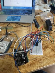
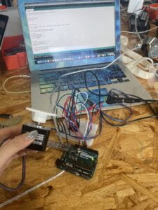
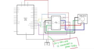
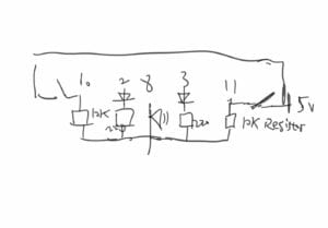
The circuit appeared difficult at first, but after it was obvious that all of the grey lines were linked to ground and virtually all of the red lines were connected to 5V, everything fell into place. However, I made a critical error that almost resulted in the death of my Arduino. I connected all of the red lines to the single Arduino red line, then to both 5V and the power supply, which was a mistake. Step 1 was completed successfully, and step 2 was completed successfully until the motor failed in step 3.

Code:

/*
MotorKnob

A stepper motor follows the turns of a potentiometer
(or other sensor) on analog input 0.

http://www.arduino.cc/en/Reference/Stepper
This example code is in the public domain.
*/

#include <Stepper.h>

// change this to the number of steps on your motor
#define STEPS 200

// create an instance of the stepper class, specifying
// the number of steps of the motor and the pins it’s
// attached to
Stepper stepper(STEPS, 8, 9, 10, 11);

// the previous reading from the analog input
int previous = 0;

void setup() {
// set the speed of the motor to 30 RPMs
stepper.setSpeed(30);
}

void loop() {
// get the sensor value
int val = analogRead(0);

// move a number of steps equal to the change in the
// sensor reading
val = map(val, 0, 1023, 0, 200);
stepper.step(val – previous);

// remember the previous value of the sensor
previous = val;
}


Question 1: What kind of machines would you be interested in building? Add a reflection about the use of actuators, the digital manipulation of art, and the creative process to your blog post.

After reading ART+Science NOW, I would like to build machines that involve the interaction between humans and the LED lights. I want to create something for hearing disability people. It will be a setting that can reflect peoples voice volume. The led will change colors according to the volume. 

The actuator for this machine might be an sound sensor and an LED screen that fills with LEDs. To be more precise, there need to be many infrared distance sensors, which are used to detect people to make sure its the human that’s making sound. 

The Arduino first needs to read what the sensors have detected, which indicates people’s voice. The changing values of some sensors indicate the volume of the voice. The output of the machine is the changes in LEDs lighting. Different people’s voice may influence the LEDs’lighting. The programming of controlling the lighting of the LEDs might be difficult and sophisticated.

I believe the creative process is mostly determined by how the LEDs will vary in response to the data collected by the sensor. It provides a lot of room for innovation. It may be used for commercial marketing or just for enjoyable engagement, for example. The application may be varied, and diverse creations can be filled with a variety of creativity.

Question 2: Choose an art installation mentioned in the reading ART + Science NOW, Stephen Wilson (Kinetics chapter). Post your thoughts about it and make a comparison with the work you did during this recitation. How do you think that the artist selected those specific actuators for his project?

Louis-Philippe Demers and Garry Stewart, Devolution, 2006

This interactive work of art portrays robots as equals to human dancers, as well as demonstrating how human actions affect robot behavior in the context of “ecosystem dynamics.” The connection between humans and robots is similar to what we’ve seen with our sketching machine. However, in our recitation, we viewed our computer as a tool rather than a human being. The actuators in the project demonstrated the beauty of machinery’s rhythm when performing dance. In other words, their erratic mechanical movement contrasted with human dancers’ graceful movement.

Interaction lab group project 1 final reflection

Our performance Exoconscience

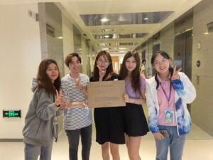
My group members were: Anthony, Sissy, Angel, and Grace.

Due to the typhoon, we had our first meeting through Zoom. We briefly discussed our thoughts from the books and chose which innovation should be recreated. We first intended to use the idea of the glove that connects to the brain to portray the emotions based on The Winter Market and its main character.

We then held a face-to-face discussion to discuss how to implement the notion. However, we discovered that attaching the headgear and glove would be challenging. Furthermore, having two inventions will prevent other participants from participating in the project (you would only need just one person to perform). As a result, we opted to solely create the glove and use the exoskeleton technique. We chose one of our group members to be the ‘puppet’ who receives input (emotion) from ‘outsiders.’ With an exoskeleton, the outsiders control the puppet’s movement and emotions. This way, we could all take part in the performance.

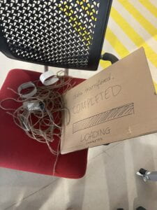
We got together again to make the glove after thoroughly planning it out. We debated whether to create the glove out of the box or to use other gloves, such as mountain gloves. We were also unsure about how to recreate the exoskeleton because we knew we couldn’t use advanced technology like a 3D printer or laser cutter. We used wool strings as a tool for both the glove and the exoskeleton to address these concerns.

In addition, we placed several cardboard boxes to serve as joints. The puppet’s movement may be more easily controlled because to these “joints.” We were able to adjust the stiffness and shape of the stiff cardboard by using the scoring cutting technique that my other group member and I observed at the cardboard session. Furthermore, instead of using a glue gun to attach the joint rings, we used velcro tapes to make it easier to connect and detach the rings.

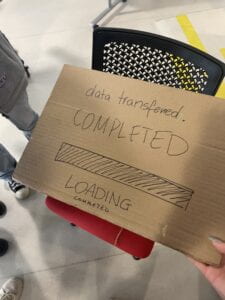
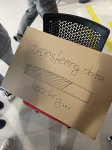
We also sought to use as little sound as possible and to interact with the audience in ways other than acting/skit. However, we thought that our idea lacked a lot of interactive elements. We created the loading screen for the puppet to let the viewer know that the puppet and its emotions are being gradually manipulated.
The joint rings are one of the elements that can be improved. It fell off twice throughout the performance and had to be reattached. I feel part of the cause is that we did not secure it tightly enough to the actor’s arms, but I believe we can strengthen it.

Our concept is inspired by the Winter Market. The protagonist of that story has some of her spirit and consciousness in a ‘robot.’ This sparked our idea to create an exoskeleton to carry her spirit. As a result, when people suffer from physical diseases or injuries, their awareness can be input into the exoskeleton, which carries the people’s spirit. However, it may have a number of disadvantages. For example, as indicated in the novel, the female heroine is frequently unsure about herself: whether she is herself or a robot. People in this exoskeleton cannot govern themselves using their own awareness; instead, they are controlled by the outside world. As a result, we decided to show it to the audience. We build rings out of cardboard and ropes and place them on a person’s body to make him look like a puppet. People close to him use the strings to manipulate him into performing the activities, implying that, despite having his spirit in this exoskeleton, he was unable to govern himself and therefore lost his right to his own body. What about his spirit? Is that also under control? So, who exactly is he? Is he still the same person? Those questions have remained in our minds, and we want to show them to the public as well.

Throughout the process, I offered my interactive artifact ideas. The concept is a combination of my own and another group member’s ideas. Also, my group members and I have discussed a lot of our final idea, and I believe I have put forward some valuable views during the conversation that are very beneficial in improving our final product and performance. During the construction process, I assisted with cutting and bending the cardboard, as well as sticking the strings and other items to the card boards.

I believe this artifact has certain benefits since it can assist persons who have physically suffered from accidents or diseases in getting rid of the physical agony while maintaining their spiritual life. However, it can still be troublesome because issues such as “who is actually directing this body” may arise. As a result, I believe this is a really complicated problem.

I truly like the group of life trackers’ performance. They created a life tracker to monitor a person’s safety, happiness, and health, among other things. They acted out a person’s entire life with the help of a life tracker named Shadow.

Their style is inspired by the Fish in Lijiang. I was having some difficulty linking their item and performance to the story. However, the technological environment is very similar, and that artifact appears to be something that could be invented at the period. Furthermore, the protagonist loses control of his life and loses his sense of time, which is somewhat pertinent to what they have done. In summary, the performance is really appealing and intriguing. To improve their overall performance, I would advise them to stay more within the context of the story, as I am experiencing a disconnect between their work and the story.

Interaction lab recitation 3 documentation blog post

Ultrasonic Ranger:  [1]  The Ultrasonic Ranger (AKA Ultrasonic Sensor OR  HC-SR04) can be used to detect distance. To program the Arduino to work with this sensor,  you can use this post or use the Ping example .

[1] (Arduino>File>Examples>0.6Sensors>Ping). In order for the HC-SR04 to work with the Ping code, you MUST connect both Trig and Echo to the same Digital Pin in your Arduino.
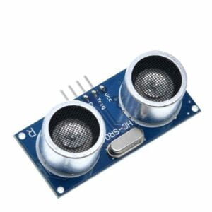
Picture from sparkfun.com

Question 1: What did you intend to assemble in the recitation exercise? If your sensor/actuator combination were to be used for pragmatic purposes, who would use it, why would they use it, and how could it be used?

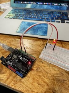
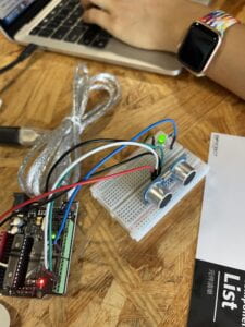
We want to connect the led lights to the ultrasonic rangefinder to create a light that varies in response to the object’s distance. This device is suitable for use on a deep-sea sounder. The stronger the light is, the closer the object in front of you is. This device has the potential to act as a watchdog.

Question 2: Code is often compared to following a recipe or tutorial.  Why do you think that is?

Code is similar to a recipe or tutorial in that it instructs a machine on what to do with its physical components in order to create outcomes as a function. In comparison, newborns have the instruments, in the shape of body parts, to conduct motor actions such as movement if their parents tell or teach them how. Similarly, computers and other types of hardware, such as the arduino, can transmit electricity via different hard components to achieve diverse functions, but they can’t unless someone, in this instance code, teaches them how to direct their signals and electricity.

Question 3: In The Language of New Media, Manovich describes the influence of computers on new media. In what ways do you believe the computer influences our human behaviors?

I feel that the computer’s fast-forward features, as well as its access to social media, have introduced new hobbies and interests to computer users. Furthermore, improved computation enables people to build more algorithms and applications, allowing for greater creativity.

<pre>

<font color=”#434f54″>// —————————————————————- //</font>

<font color=”#434f54″>// Arduino Ultrasoninc Sensor HC-SR04</font>

<font color=”#434f54″>// Re-writed by Arbi Abdul Jabbaar</font>

<font color=”#434f54″>// Using Arduino IDE 1.8.7</font>

<font color=”#434f54″>// Using HC-SR04 Module</font>

<font color=”#434f54″>// Tested on 17 September 2019</font>

<font color=”#434f54″>// —————————————————————- //</font>


<font color=”#5e6d03″>#define</font> <font color=”#000000″>echoPin</font> <font color=”#000000″>2</font> <font color=”#434f54″>// attach pin D2 Arduino to pin Echo of HC-SR04</font>

<font color=”#5e6d03″>#define</font> <font color=”#000000″>trigPin</font> <font color=”#000000″>3</font> <font color=”#434f54″>//attach pin D3 Arduino to pin Trig of HC-SR04</font>

<font color=”#00979c”>int</font> <font color=”#000000″>outputValue</font> <font color=”#434f54″>=</font> <font color=”#000000″>9</font><font color=”#000000″>;</font> &nbsp;&nbsp;&nbsp;&nbsp;&nbsp;&nbsp;&nbsp;<font color=”#434f54″>// value output to the PWM (analog out)</font>

<font color=”#00979c”>int</font> <font color=”#000000″>led</font> <font color=”#434f54″>=</font> <font color=”#000000″>9</font><font color=”#000000″>;</font>

<font color=”#434f54″>// defines variables</font>

<font color=”#00979c”>long</font> <font color=”#000000″>duration</font><font color=”#000000″>;</font> <font color=”#434f54″>// variable for the duration of sound wave travel</font>

<font color=”#00979c”>int</font> <font color=”#000000″>distance</font><font color=”#000000″>;</font> <font color=”#434f54″>// variable for the distance measurement</font>

<font color=”#00979c”>int</font> <font color=”#000000″>analogOutPin</font><font color=”#000000″>;</font>

<font color=”#00979c”>void</font> <font color=”#5e6d03″>setup</font><font color=”#000000″>(</font><font color=”#000000″>)</font> <font color=”#000000″>{</font>

&nbsp;&nbsp;<font color=”#d35400″>pinMode</font><font color=”#000000″>(</font><font color=”#000000″>led</font><font color=”#434f54″>,</font> <font color=”#00979c”>OUTPUT</font><font color=”#000000″>)</font><font color=”#000000″>;</font>

&nbsp;<font color=”#d35400″>pinMode</font><font color=”#000000″>(</font><font color=”#000000″>trigPin</font><font color=”#434f54″>,</font> <font color=”#00979c”>OUTPUT</font><font color=”#000000″>)</font><font color=”#000000″>;</font> <font color=”#434f54″>// Sets the trigPin as an OUTPUT</font>

&nbsp;<font color=”#d35400″>pinMode</font><font color=”#000000″>(</font><font color=”#000000″>echoPin</font><font color=”#434f54″>,</font> <font color=”#00979c”>INPUT</font><font color=”#000000″>)</font><font color=”#000000″>;</font> <font color=”#434f54″>// Sets the echoPin as an INPUT</font>

&nbsp;<b><font color=”#d35400″>Serial</font></b><font color=”#434f54″>.</font><font color=”#d35400″>begin</font><font color=”#000000″>(</font><font color=”#000000″>9600</font><font color=”#000000″>)</font><font color=”#000000″>;</font> <font color=”#434f54″>// // Serial Communication is starting with 9600 of baudrate speed</font>

&nbsp;<b><font color=”#d35400″>Serial</font></b><font color=”#434f54″>.</font><font color=”#d35400″>println</font><font color=”#000000″>(</font><font color=”#005c5f”>”Ultrasonic Sensor HC-SR04 Test”</font><font color=”#000000″>)</font><font color=”#000000″>;</font> <font color=”#434f54″>// print some text in Serial Monitor</font>

&nbsp;<b><font color=”#d35400″>Serial</font></b><font color=”#434f54″>.</font><font color=”#d35400″>println</font><font color=”#000000″>(</font><font color=”#005c5f”>”with Arduino UNO R3″</font><font color=”#000000″>)</font><font color=”#000000″>;</font>

<font color=”#000000″>}</font>

<font color=”#00979c”>void</font> <font color=”#5e6d03″>loop</font><font color=”#000000″>(</font><font color=”#000000″>)</font> <font color=”#000000″>{</font>

&nbsp;<font color=”#434f54″>// Clears the trigPin condition</font>

&nbsp;<font color=”#d35400″>digitalWrite</font><font color=”#000000″>(</font><font color=”#000000″>trigPin</font><font color=”#434f54″>,</font> <font color=”#00979c”>LOW</font><font color=”#000000″>)</font><font color=”#000000″>;</font>

&nbsp;<font color=”#d35400″>delayMicroseconds</font><font color=”#000000″>(</font><font color=”#000000″>2</font><font color=”#000000″>)</font><font color=”#000000″>;</font>

&nbsp;<font color=”#434f54″>// Sets the trigPin HIGH (ACTIVE) for 10 microseconds</font>

&nbsp;<font color=”#d35400″>digitalWrite</font><font color=”#000000″>(</font><font color=”#000000″>trigPin</font><font color=”#434f54″>,</font> <font color=”#00979c”>HIGH</font><font color=”#000000″>)</font><font color=”#000000″>;</font>

&nbsp;<font color=”#d35400″>delayMicroseconds</font><font color=”#000000″>(</font><font color=”#000000″>10</font><font color=”#000000″>)</font><font color=”#000000″>;</font>

&nbsp;<font color=”#d35400″>digitalWrite</font><font color=”#000000″>(</font><font color=”#000000″>trigPin</font><font color=”#434f54″>,</font> <font color=”#00979c”>LOW</font><font color=”#000000″>)</font><font color=”#000000″>;</font>

&nbsp;<font color=”#434f54″>// Reads the echoPin, returns the sound wave travel time in microseconds</font>

&nbsp;<font color=”#000000″>duration</font> <font color=”#434f54″>=</font> <font color=”#d35400″>pulseIn</font><font color=”#000000″>(</font><font color=”#000000″>echoPin</font><font color=”#434f54″>,</font> <font color=”#00979c”>HIGH</font><font color=”#000000″>)</font><font color=”#000000″>;</font>

&nbsp;<font color=”#434f54″>// Calculating the distance</font>

&nbsp;<font color=”#000000″>distance</font> <font color=”#434f54″>=</font> <font color=”#000000″>duration</font> <font color=”#434f54″>*</font> <font color=”#000000″>0.034</font> <font color=”#434f54″>/</font> <font color=”#000000″>2</font><font color=”#000000″>;</font> <font color=”#434f54″>// Speed of sound wave divided by 2 (go and back)</font>

&nbsp;<font color=”#434f54″>// Displays the distance on the Serial Monitor</font>

&nbsp;<font color=”#434f54″>//Serial.print(“Distance: “);</font>

&nbsp;<font color=”#434f54″>//Serial.print(distance);</font>

&nbsp;<font color=”#434f54″>//Serial.println(” cm”);</font>


&nbsp;<font color=”#434f54″>// map it to the range of the analog out:</font>

&nbsp;<font color=”#000000″>outputValue</font> <font color=”#434f54″>=</font> <font color=”#d35400″>map</font><font color=”#000000″>(</font><font color=”#000000″>distance</font><font color=”#434f54″>,</font> <font color=”#000000″>0</font><font color=”#434f54″>,</font> <font color=”#000000″>20</font><font color=”#434f54″>,</font> <font color=”#000000″>255</font><font color=”#434f54″>,</font> <font color=”#000000″>0</font><font color=”#000000″>)</font><font color=”#000000″>;</font>

&nbsp;

&nbsp;<b><font color=”#d35400″>Serial</font></b><font color=”#434f54″>.</font><font color=”#d35400″>println</font><font color=”#000000″>(</font><font color=”#000000″>outputValue</font><font color=”#000000″>)</font><font color=”#000000″>;</font>

&nbsp;<font color=”#434f54″>// change the analog out value:</font>

&nbsp;<font color=”#434f54″>//analogWrite(analogOutPin, outputValue);</font>

&nbsp;<font color=”#d35400″>analogWrite</font><font color=”#000000″>(</font><font color=”#000000″>led</font><font color=”#434f54″>,</font><font color=”#000000″>outputValue</font><font color=”#000000″>)</font><font color=”#000000″>;</font>

&nbsp;<font color=”#000000″>}</font>

<font color=”#000000″>}</font>


</pre>


// —————————————————————- //

// Arduino Ultrasoninc Sensor HC-SR04

// Re-writed by Arbi Abdul Jabbaar

// Using Arduino IDE 1.8.7

// Using HC-SR04 Module

// Tested on 17 September 2019

// —————————————————————- //


#define echoPin 2 // attach pin D2 Arduino to pin Echo of HC-SR04

#define trigPin 3 //attach pin D3 Arduino to pin Trig of HC-SR04

int outputValue = 9;       // value output to the PWM (analog out)

int led = 9;

// defines variables

long duration; // variable for the duration of sound wave travel

int distance; // variable for the distance measurement

int analogOutPin;

void setup() {

  pinMode(led, OUTPUT);

 pinMode(trigPin, OUTPUT); // Sets the trigPin as an OUTPUT

 pinMode(echoPin, INPUT); // Sets the echoPin as an INPUT

 Serial.begin(9600); // // Serial Communication is starting with 9600 of baudrate speed

 Serial.println(“Ultrasonic Sensor HC-SR04 Test”); // print some text in Serial Monitor

 Serial.println(“with Arduino UNO R3”);

}

void loop() {

 // Clears the trigPin condition

 digitalWrite(trigPin, LOW);

 delayMicroseconds(2);

 // Sets the trigPin HIGH (ACTIVE) for 10 microseconds

 digitalWrite(trigPin, HIGH);

 delayMicroseconds(10);

 digitalWrite(trigPin, LOW);

 // Reads the echoPin, returns the sound wave travel time in microseconds

 duration = pulseIn(echoPin, HIGH);

 // Calculating the distance

 distance = duration * 0.034 / 2; // Speed of sound wave divided by 2 (go and back)

 // Displays the distance on the Serial Monitor

 //Serial.print(“Distance: “);

 //Serial.print(distance);

 //Serial.println(” cm”);


 // map it to the range of the analog out:

 outputValue = map(distance, 0, 20, 255, 0);


 Serial.println(outputValue);

 // change the analog out value:

 //analogWrite(analogOutPin, outputValue);

 analogWrite(led,outputValue);

 }

}
IMG_3721IMG_3722
 

Interaction lab recitation 2 documentation blog post

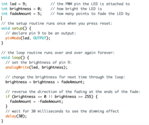
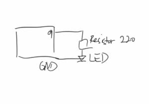
Circuit 1: Fade
The circuit is intended to produce a process in which an LED light dims and then shines again. Because this circuit was very basic, I was able to create the circuit effortlessly after a short refresher of how electricity connects on a breadboard.


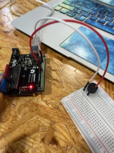
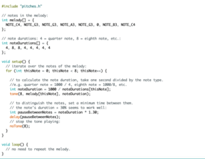
Circuit 2: toneMelody
The second circuit is designed to generate noises from a speaker through a breadboard, with the tones varying according to the computer code. We could vary the tempo and tones of the music played by changing the computer code, allowing us more creativity in the end product. Because the circuit was very easy, it was finished quickly.

IMG_3703

Circuit 3: Speed Game
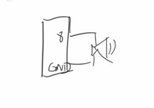
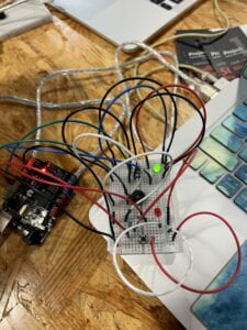
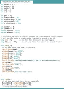
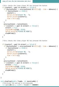
The final circuit was probably the most difficult to build since it required complicated electrical connections and a variety of different components such as resistors, LEDs, and a speaker. The game pits two players against one other in a race to press a push button on the breadboard. A serial monitor can be used to view the results. The most difficult aspect of this circuit was properly connecting the correct wires to the various components. Area management on the breadboard was also important, since the crowded arrangement of the different wires from the positive side made it difficult to determine which wire belonged in which location.

IMG_3704

Material I used:

1 * Arduino Uno,1 * USB A to B cable,1 * breadboard,1 * buzzer,2 * LEDs, 2 * 220 ohm resistors 2 * 10K ohm resistors, 2 * pushbuttons,A handful of jumper cables

Question 1: Propose another kind of creative button you could use in Circuit 3 to make the game more interactive. Read and use some material from the Introduction Chapter (pages xvii to xxix) of Physical Computing to explain why this button would make this game more interactive.
“Input is usually easier than output because it takes less energy to sense activity than to move things.” (Introduction xx) 

We could make the button larger to increase interaction. People can expend less energy in order to locate the little, tiny button on the breadboard. Such activities need less energy, which enhances interaction.

Question 2: Why did we use a 10K resistor with each push button? (Read the short explanation about pull-down resistors here)

Resistors are used to prevent short circuits by resisting voltage. The 10k resistors were used to prevent the 5V from connecting directly to the breadboard’s GND side, which would result in a short circuit.

Interaction lab fiction blog post

 3 short fiction stories

Story1:The winter market

Using technological headgear, transferring human memories and souls to a robotic body. For this transmission to take place, the human must consent to data being transferred to the robotic body, with the human body ceasing to respond once the transfer is complete. The human will subsequently be placed in a robotic body and will remain in it for the remainder of their lives. And if a part of the body is broken he or she can replace it and switch to a new body using the same technology.

Story 2: Newton’s Sleep 

Viruses and contamination have forced humanity into SPES due to a virus outbreak on Earth in the story Fisherman of the Inland Sea – Newton’s Sleep. The persons chosen for the SPES were chosen for their high quality and live in a confined environment.

The SPES Society’s mental health may be severely harmed as a result of their absence from their mother planet. Virtual reality can be used to recreate Earth’s environment onto the SPES communit2y as part of an interactive media project. Virtual Reality is a sensor-based virtual experience that allows a person to travel around an alternate environment online.

Members of the SPES society can use this, together with Earth’s geographical data, to mimic Earth’s experience, allowing them to remember and experience Earth once more. Virtual Reality is now a reality in our society, but with limited capability and usefulness. Virtual reality, on the other hand, should be able to employ sensors to imitate actual touch by changing the texture of an interactive medium, thanks to advanced technology already available from space colonies.

Story 3: the fish of Lijiang

Our main character was required to complete neurological rehabilitation treatment in Lijiang in order to increase labor productivity. Everything in this beautiful lijiang, including the fish swimming in the pond, is a fabrication.

What I’d like to create is a virtual reality setting based on the concept of “time sense dilation therapy” from the short fiction. However, rather than utilizing it on elderly wealthy guys, I would like to use it on mentally ill people.

“By manipulating certain receptors in the pineal gland, it was possible to slow down one’s sense of time, to dilate it. The body of a person receiving time sense dilation therapy remains in the normal stream of time, but his mind experiences time a hundred, a thousand times slower than the rest of us.”(Chen)

Simultaneously, the VR setting might conjure up a vast paradise in one’s head and provide proper treatment. One may feel as if they have lived for ten years, yet in actuality they have only been for one hour.

Interaction Lab blog post assignment 1

Interaction can occur between people or between people and objects.

Interaction, in my perspective, is when you perform an action, engage with people or objects, and receive feedback.


One that aligns with my definition

“The Lightwave”

https://www.manamana.net/video/detail?id=70417#!zh

It is “an interactive light sculpture commissioned by one of the biggest music festivals in Poland.”

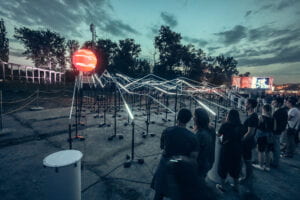
The appearance of light waves is determined by who is drumming. The faster the drumming, the faster the lights appear. This project aligns with my definition of interaction in that any action you take can result in corresponding feedback, which in this case is when you drum, the lightwave appears.

Each drum represents a long bulb tube that leads to a massive circle lamp. The lamps will turn on and off in time with the beat of the drum. 

One that does not aligns with my definition of interaction

https://www.manamana.net/video/detail?id=1578178#!zh

The experience invites customers to wander through an interactive natural world—both real and digital

The pop-up is brought to life by a sensory-stimulating digital application that taps into the Coach Forever SS21 presentation’s palette and purpose. It is an experience that explores several tensions: the natural world and the city, legacy and the future of fashion, tactile leatherwork, and interactive technology, all through the prism of optimism and craft.

The reason, why I think it does not align with my understanding of interaction, is that there is no input and feedback. There are basically just segments of the screen moving around and sound creating an environment.

Recitation documentation blog post

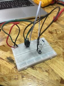
First circuit:Doorbell

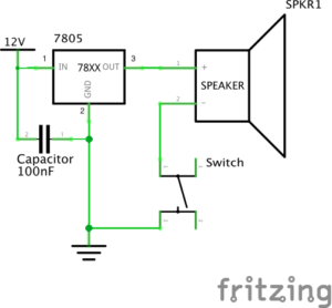
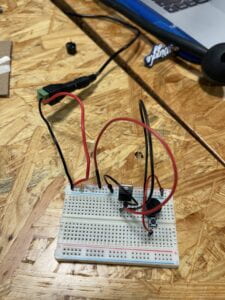
Components: a speaker, a switch, a 100 nF capacitator, a voltage regulator, and a 12v power supply. 

At first, the speaker, capacitor, and switch were on the same line which caused it to become a short circuit. After realizing the problem and fixing it, we were able to use the switch to successfully control the speaker and make a sound.

Second: Lamp

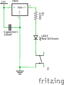
Components: a LED, a switch, a 100 nF capacitator, a voltage regulator, and a 12v power supply. 

The same issue happened again. The LED, the switch, and the capacitor were sharing the same line which created a short circuit. We immediately fixed it by looking at the image of the inner structure to find the correct orientation. Finally we were able to use the switch to control LED switching on and off.

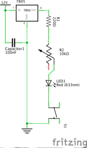
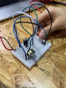
Third: Dimmable Lamp

Components: a variable resistor, a LED, a switch, a 100 nF capacitator, a voltage regulator, and a 12v power supply. 

The variable resistor was introduced in the previous circuit. Because moving the knob changes the amount of resistance the potentiometer delivers to voltage.  As a result, we can adjust the voltage in the form of light brightness on the LED light by connecting a potentiometer to it.

Question 1: In what way do you think that the circuits you built today include interactivity? 

The definition of interaction, according to The Art of Interactive Design, is “a cyclic process in which two actors alternately listen, think, and communicate.” All of the circuits I built had an input and an output. The breadboard “listens” to the input of the push-button sensor and “speaks” through the output of a speaker, dimmable light, or lamp, as the author symbolically states.

Question 2: How can Interaction Design and Physical Computing be used to create Interactive Art?

Users can create and execute circuits with customized outputs and input possibilities using interaction design and computing. We were able to utilize a simple input like a push-button to create a range of outputs ranging from light to music using diverse combinations like the ones exhibited in our recitation circuits. As a result, physical computing may be utilized to turn interaction ideas and designs into motion by converting actions into physical responses and interactions.