Circuit 1: Fade
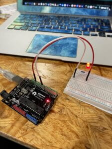
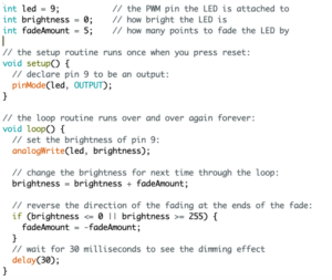
The circuit is intended to produce a process in which an LED light dims and then shines again. Because this circuit was very basic, I was able to create the circuit effortlessly after a short refresher of how electricity connects on a breadboard.
Circuit 2: toneMelody
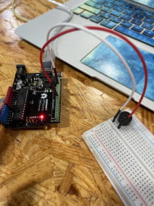
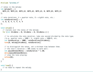
The second circuit is designed to generate noises from a speaker through a breadboard, with the tones varying according to the computer code. We could vary the tempo and tones of the music played by changing the computer code, allowing us more creativity in the end product. Because the circuit was very easy, it was finished quickly.

Circuit 3: Speed Game
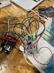
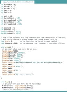
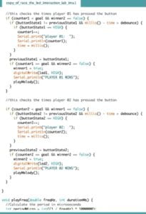
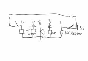
The final circuit was probably the most difficult to build since it required complicated electrical connections and a variety of different components such as resistors, LEDs, and a speaker. The game pits two players against one other in a race to press a push button on the breadboard. A serial monitor can be used to view the results. The most difficult aspect of this circuit was properly connecting the correct wires to the various components. Area management on the breadboard was also important, since the crowded arrangement of the different wires from the positive side made it difficult to determine which wire belonged in which location.
Material I used:
1 * Arduino Uno,1 * USB A to B cable,1 * breadboard,1 * buzzer,2 * LEDs, 2 * 220 ohm resistors 2 * 10K ohm resistors, 2 * pushbuttons,A handful of jumper cables
Question 1: Propose another kind of creative button you could use in Circuit 3 to make the game more interactive. Read and use some material from the Introduction Chapter (pages xvii to xxix) of Physical Computing to explain why this button would make this game more interactive.
“Input is usually easier than output because it takes less energy to sense activity than to move things.” (Introduction xx)
We could make the button larger to increase interaction. People can expend less energy in order to locate the little, tiny button on the breadboard. Such activities need less energy, which enhances interaction.
Question 2: Why did we use a 10K resistor with each push button? (Read the short explanation about pull-down resistors here)
Resistors are used to prevent short circuits by resisting voltage. The 10k resistors were used to prevent the 5V from connecting directly to the breadboard’s GND side, which would result in a short circuit.
