For Task 1:
I with my partner first have confusion about what is buzzer because we both only see it in the diagram on the computer. Then we asked Learning Assistant Carina and she told us. We then tried to build the circuit in step 1 which is a series circuit by connecting all the components together along the current from positive pole to negative pole. When we built the circuit in the first time, the buzzer did not make any sounds. We first checked the circuit but could not find any mistakes, and then we change the buzzer and tried a new one, the circuit worked. This experience reminded me that it is significant to check the function of every component in the circuit. The final version of circuit in step1 is listed below.
For the circuit in step 2, we consider it as series-parallel circuit because it adds another line which includes LED and resistor and the current can flow through this line without having to first flow through the buzzer.
We consider the circuit in step 3 as adding another line in the circuit in step2, and this new line is not controlled by the button. We first had problems connecting the potentiometer which is different from the ones I used in my high school and then we asked help from Learning Assistant. We found that connecting one pin of potentiometer to LED and another pin to resistor could work. However, after I connected all the components together like the video shows below and push the button, I found that the LED was not lit up while the buzzer made sounds. It hinted that other lines of circuit worked smoothly but the one LED in had trouble, so I changed another LED but it still could not work. Fortunately, my partner checked the circuit I built and told me that since horizontal holes in breadboard are linked together and if the LED is put in horizontal way it would be in short-circuit current.
Then I correct the way of putting LED, the circuit works like below. Since the potentiometer can change the value of its resistor by changing the position of its wiper, the brightness of LED changes like the video shows below.
For Task 2:
In task 2, we used two pieces of cardboard, copper tape which sticks on both sides of cardboard, and wires to try to build a switch. During the entire process, I think the part that uses electric soldering iron to melt iron wire and thus make the wire connecting with card board is quite interesting. We used paper tapes to stick wires with cardboard in class2 but the wires can get out of the paper tape easily, so this new method can work well. However, it is difficult for me to hold the electric soldering iron firmly like the video show below, so I practiced for several minutes to melt more so that the wire could be ensured to be firmed with cardboard.
For Task 3:
I replaced the push button with the DIY paddle switch with my teammates and then we first tested it with the circuit we built in task1 like below. As I put the two ends of cardboards together, the buzzer made sounds.
We then used the new circuit to send morse code according to the chart provided, however, we had so much fun that we forgot to record the entire process.
Questions:
1.After reflecting on this week’s readings and the recitation exercise, I found the function of the resistor R1 in step 3 is that the LED in this line needs a resistor to assist in limiting the current which passes through LED so it would not be damaged when the potentiometer at its lowest resisting value.
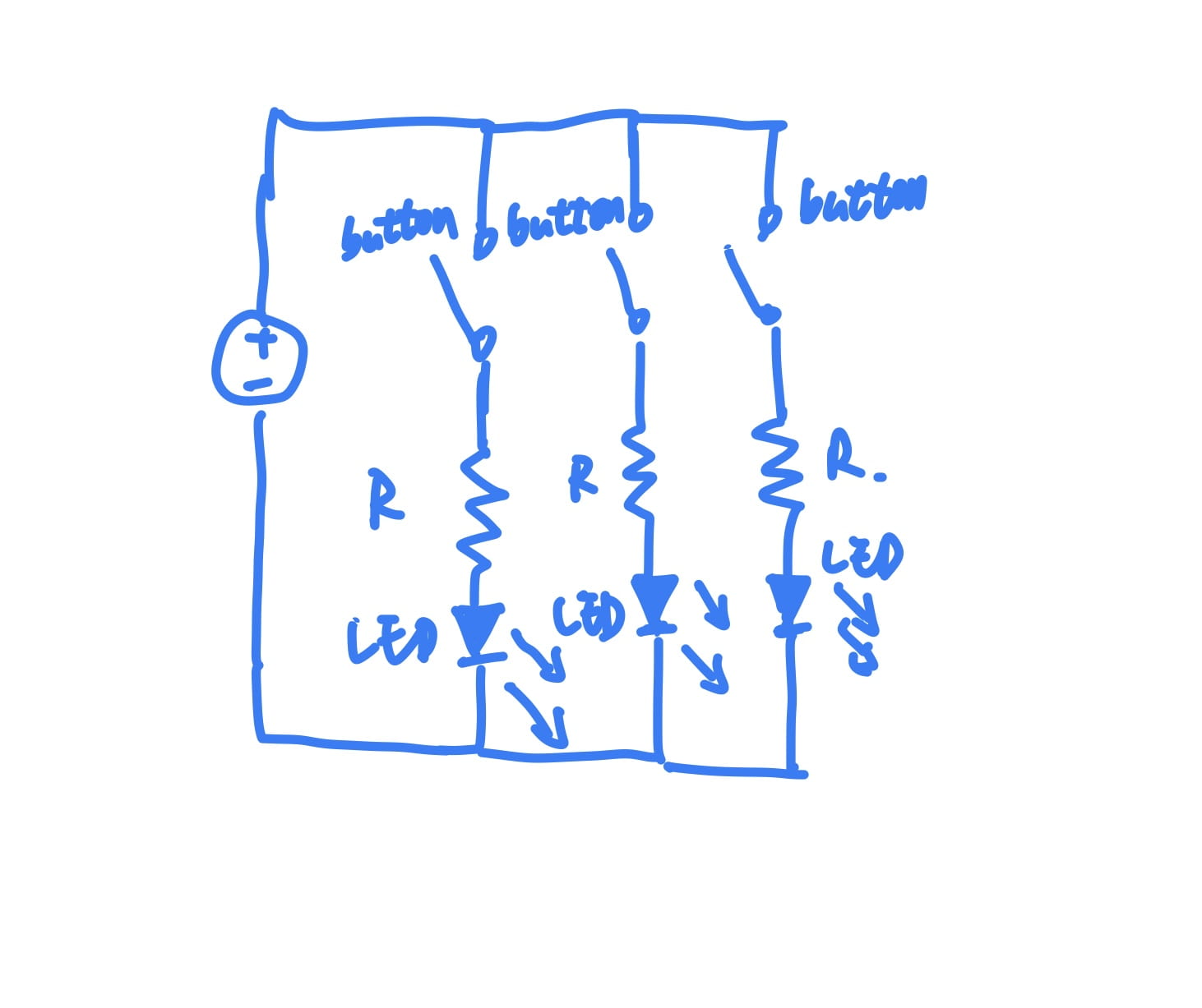
2. According to the circuit provided, I drew its diagram like below.

3. The definition of interactivity the author provided is that two actors listen, think and speak as a cycle. Therefore, I consider the circuit I built at recitation1 class in task3 includes interactivity because the circuit listens (to the paddles controlled by me), thinks (with turning on the entire circuit by the paddle as a switch) and speaks (by making sounds from buzzer). I consider the degree of interactivity it possesses is low because each action of the actor circuit is simple. I just controlled the paddles by making two pieces of cardboard together and the logistic of how the current runs in this circuit is easy. The circuit only speaks by making sounds from buzzer which has little entertainment and can not be included in the art dimension.
4. I think combining Interaction Design as fundamental logistic and Physical Computing as technical basic can lead to the creation of Interactive Art. As Zack Lieberman mentioned in his speech, he made a project named Eyewriter which was designed for a person who was a graffiti writer and suffered from diseases and thus was not able to move his arms and legs. The project can draw patterns by keeping track of users’ eyes, therefore, patients who are not able to move their arms can draw or write with their eyes. Except the designing part, this project actually involved another two parts, hardware that can get the track of eyes and present the final outcome on the computer, software that can recognize the track and transform it into patterns on the computer. Through this project, Physical Computing actually process the visible messages conveyed from users and transform them into the visible output in artistic form while Interaction Design connects all the parts.