FINAL PROJECT: Punch your Stress out


— Alyssa and Haotong Wu
Interaction Lab, Professor Margaret
3/19/2023
Tile: Fishing Time!
Team Members: Alyssa, Haotong Wu
Instructor Name: Margerat
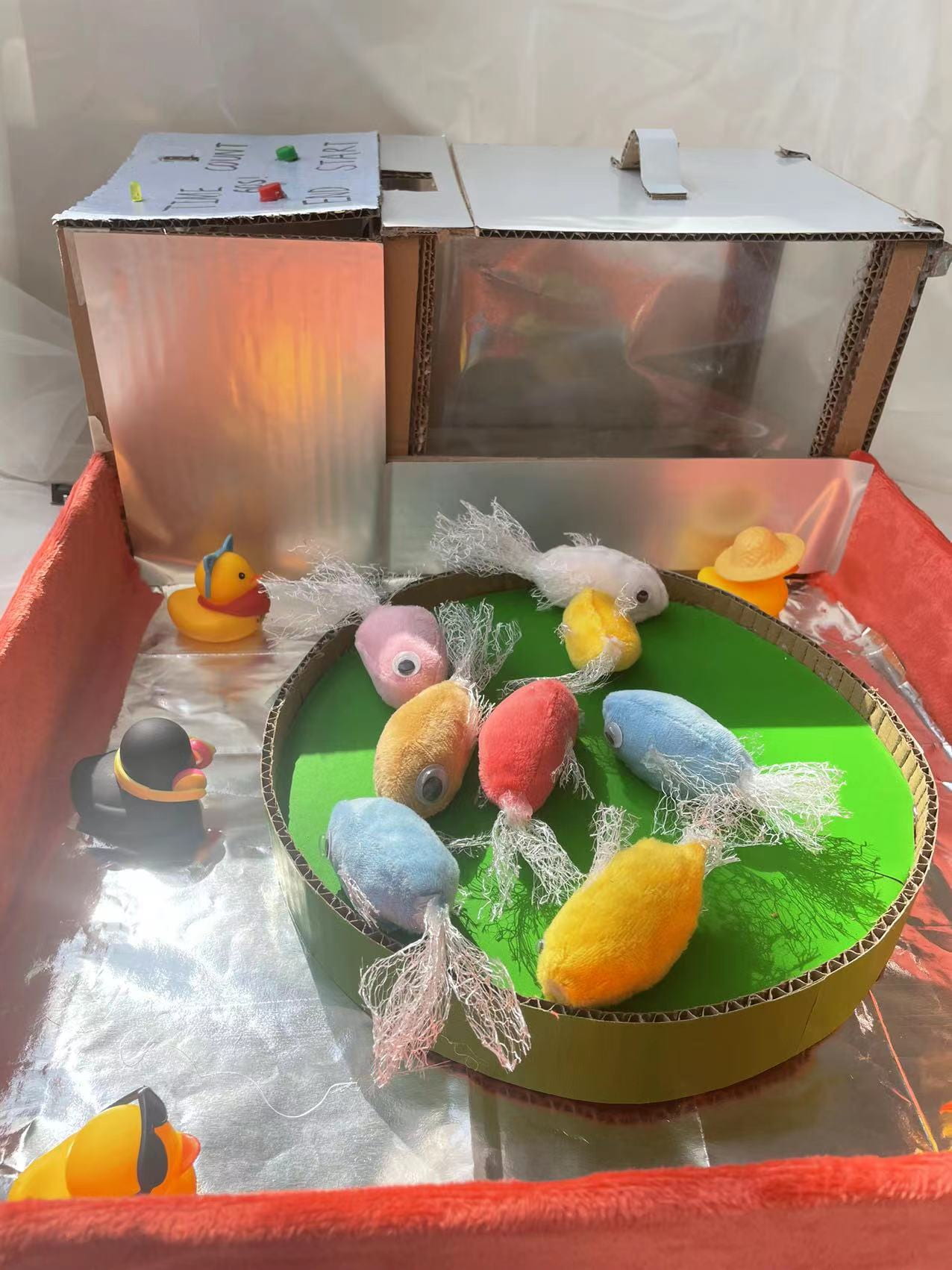
Context and Significance: The fishing simulator project was inspired by a device that uses a mechanical pulley structure. We aimed to build a fishing simulator that mimics a real fishing experience and enhances user interaction by allowing them to put on baits, control the auto-motor, and take up and roll out the fish tape. Our project aimed to increase user engagement by introducing a range of difficulty levels that develop users’ patience, and a counting device that adds interactivity. We also aimed to make the project user-friendly, convenient for both left and right-handed users, and easy to use with a magnet instead of a hook.


Conception and Design: To achieve our objectives, we divided the project into three components: a fishing rod, a turntable, and a console with a basket. I was responsible for the model design and production, while Haotong was in charge of the circuitry and coding. We used an eight-digit LED to display the fish count, and a buzzer to indicate when the user caught a fish. We also included a button to reset the count. The fishing rod was designed to be held conveniently by both left and right-handed users and attached to the side of the pool to achieve smooth use. We used a magnet instead of a hook, making it easy to hook small fish.
Fabrication and Production:
We faced challenges while building the fishing simulator, especially when connecting the eight-digit LED. However, with help from our professor and research on Arduino, we were able to understand the connection and make it work. We used cardboard to create the structure of the fishing simulator, including the pool, turntable, and console. We used the CNC machine to cut the cardboard pieces into the desired shapes, and glued them together to create the final product. We also programmed the circuitry to control the motor and count the number of fish caught.
Rod prototyping:
We started the prototyping process for the fishing rod by first identifying the materials we would use. Since our goal was to create an affordable and accessible fishing simulator, we decided to use cardboard as our main material. After gathering the necessary materials, we began sketching and cutting out the various parts of the rod, including the handle and the reel seat. We then started assembling the parts, making sure that they were sturdy and aligned properly. We found that the cardboard material was easy to work with and allowed us to iterate quickly on the design. After several rounds of prototyping, we settled on a design that was lightweight, easy to handle, and could accommodate both left and right-handed users.
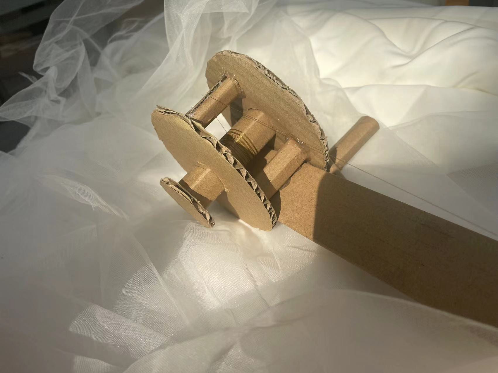
In the process of designing and prototyping the fishing rod, we encountered an issue regarding its handle. Traditionally, fishing rods are designed to be held with the dominant hand, which is usually the right hand. However, this design poses an inconvenience for left-handed individuals. Therefore, we decided to make our fishing rod user-friendly for both left and right-handed users.
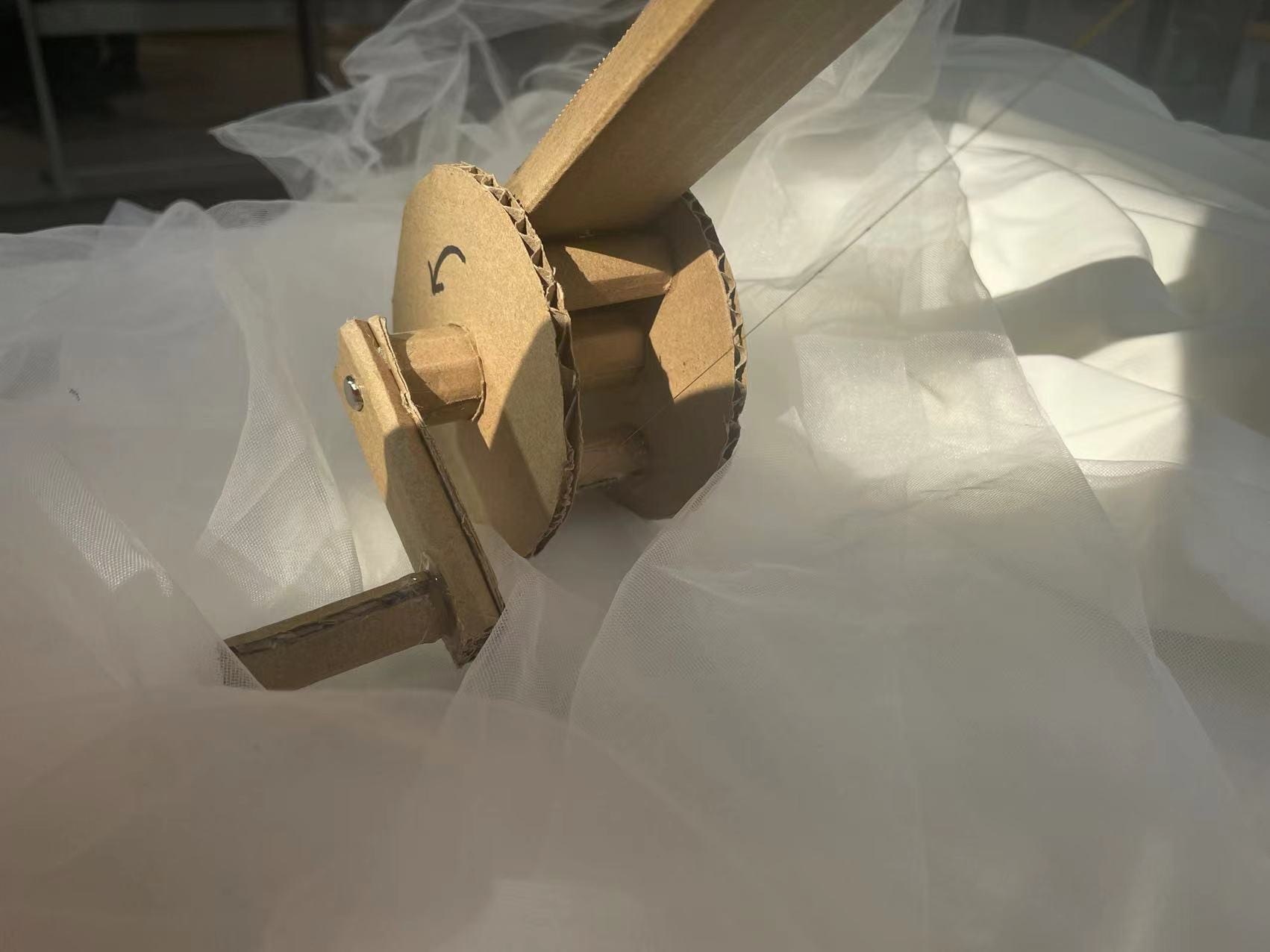
To accomplish this, we modified the design of the handle. We borrowed the method from a YouTube video for making the fishing rod, but we did not fix the fishing line. Instead, we used a straw to build a track for the fishing line. This way, both left-handed and right-handed users can use the fishing rod comfortably. This way, users can hold the fishing rod with their dominant hand and use the other hand to control the fishing line.
youtube video link: https://www.youtube.com/watch?v=YCUM22YYSE4
Overall, the design and fabrication process of the fishing rod allowed us to create a user-friendly and functional product that can be used by both left and right-handed individuals.
turntable prototyping:
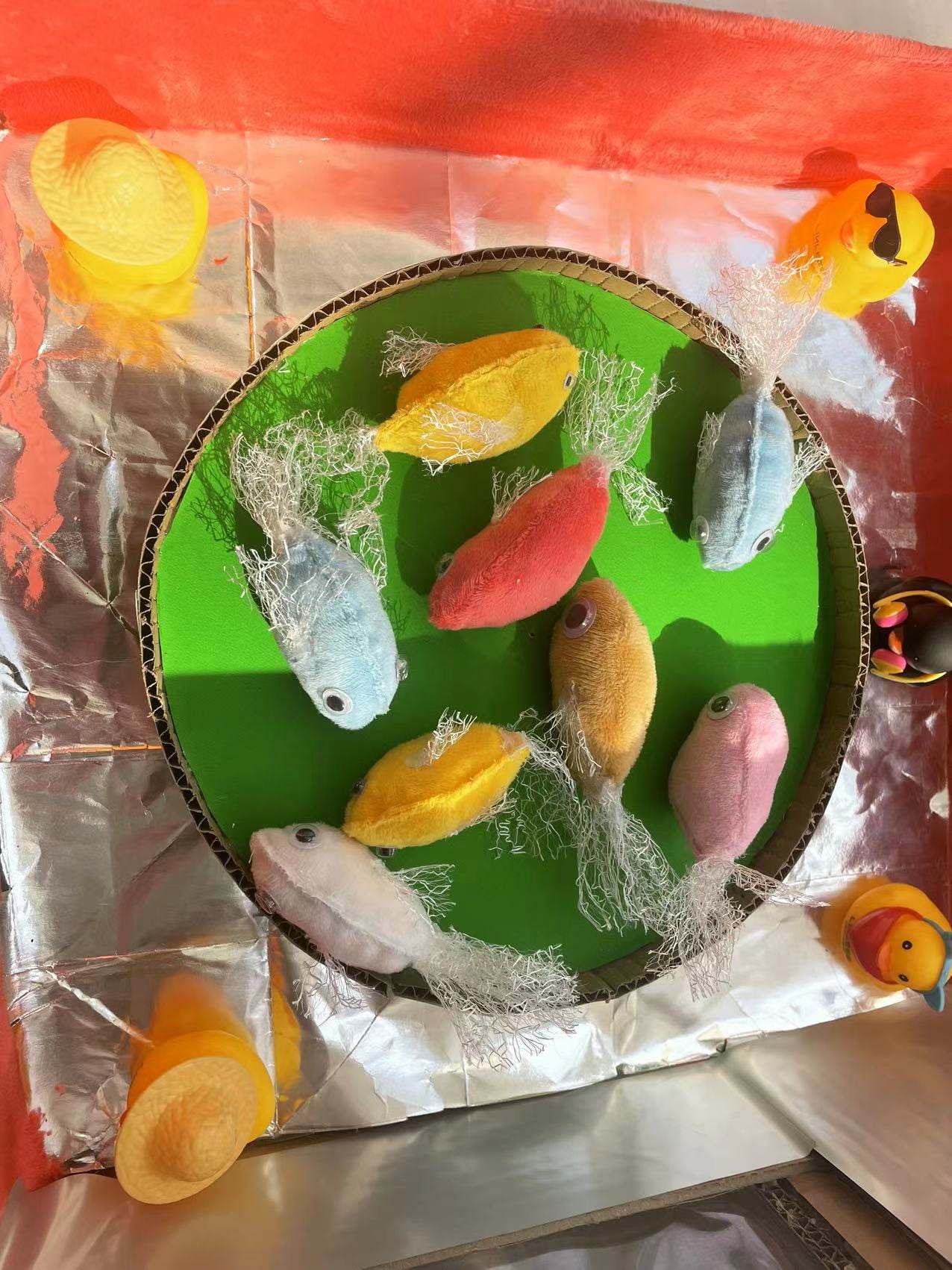
Moving on to the spinning plate, we designed a round cardboard covered with green paper to simulate the look of a lotus leaf. The plate was placed in the center of the pool, and stuffed cloth fish were placed on top of it. The plate was rotated by a servo motor, which we programmed to change direction when its position was over or equal to 180 degrees. We wanted to incorporate a button to control the playing level, but during the coding process, we discovered that we could change the speed of the spinning plate every time the fish count increased. As a result, we were able to achieve the process of leveling up without needing a separate button.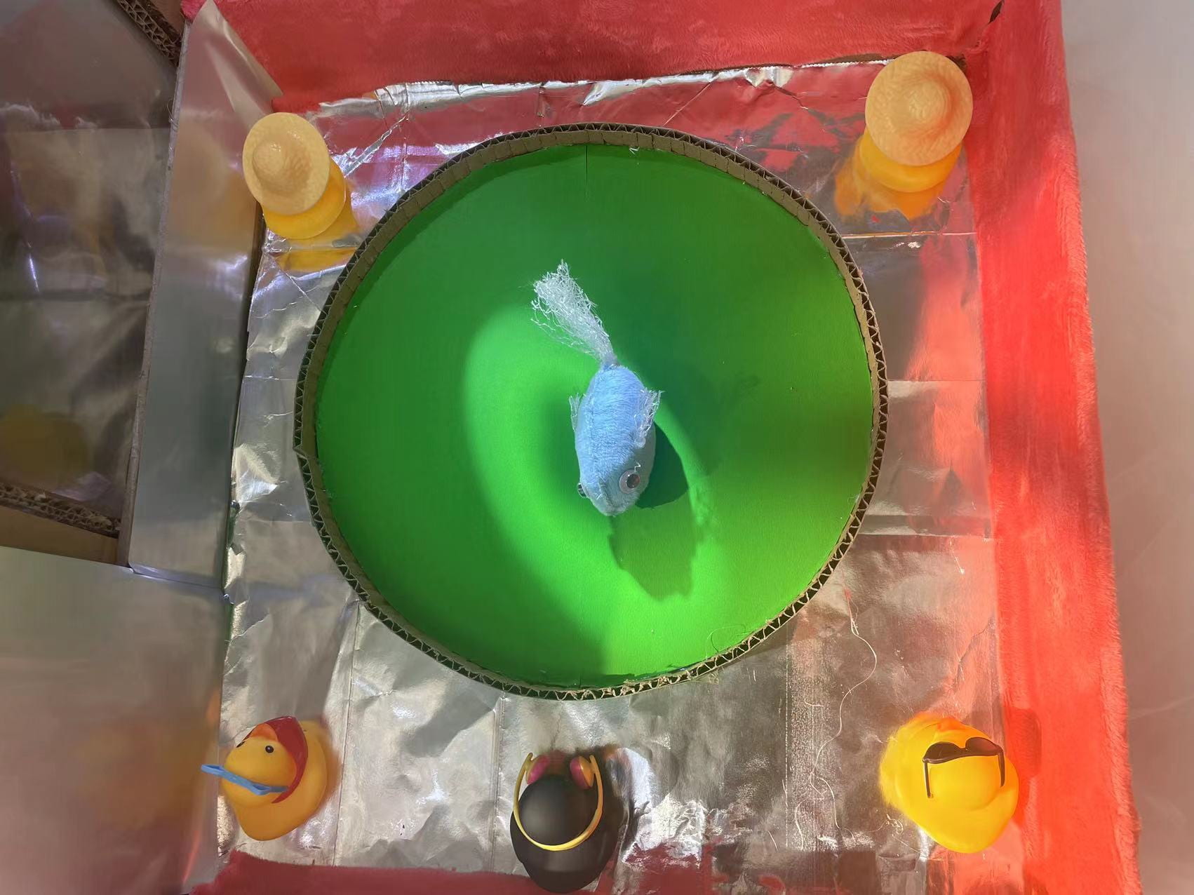
Stuffed cloth fish prototyping:
To create the stuffed cloth fish, we used a sewing machine to sew the fabric into fish shapes, leaving a small opening to fill them with stuffing. We chose a variety of colors and patterns to make the fish visually appealing. The magnets used for the fishing hooks were also sewn into the mouth area of each fish. This allowed the magnets to be concealed while still effectively catching the fish.
Magnet testing:
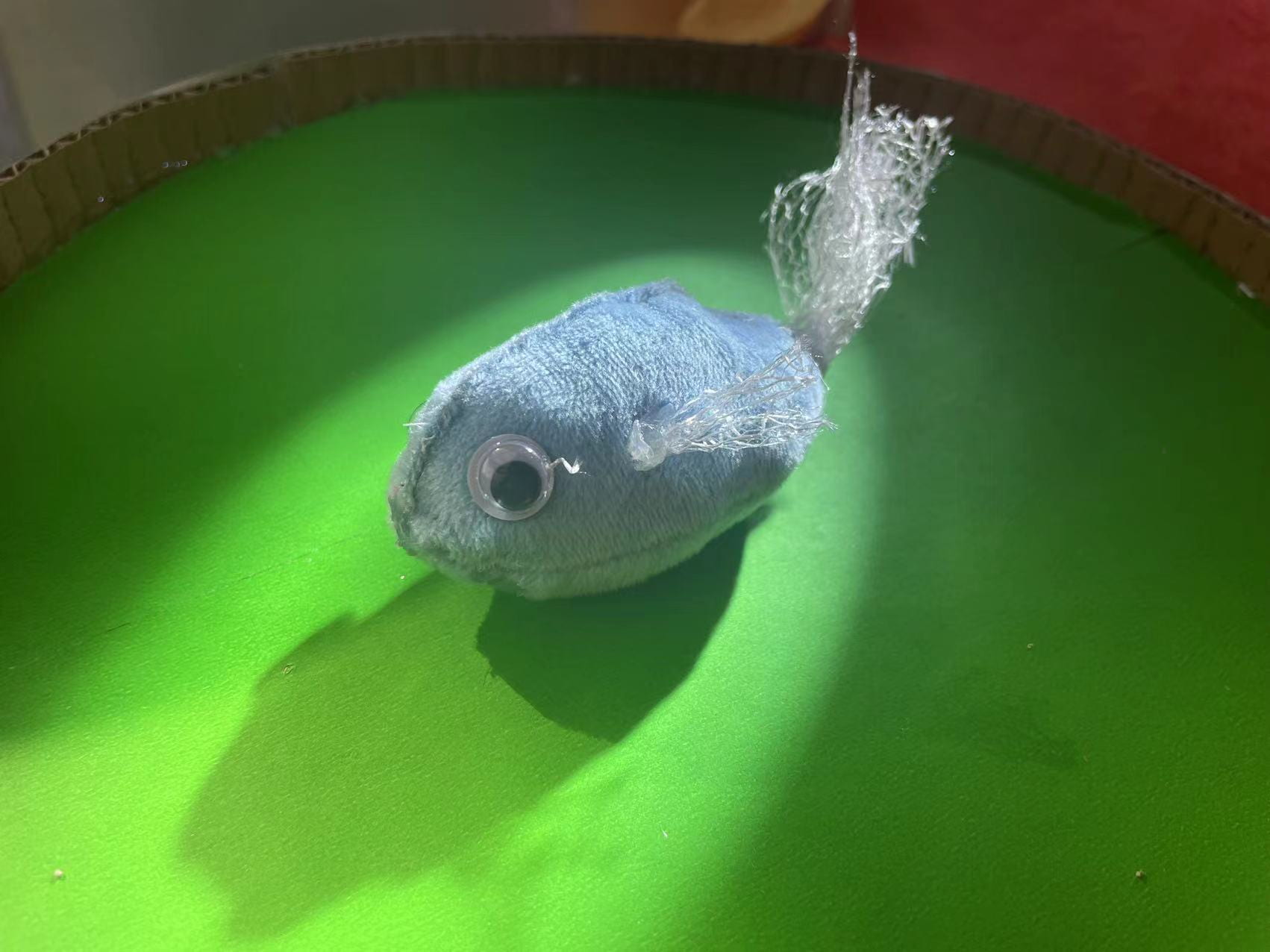
Overall, the cardboard prototyping process allowed us to quickly and easily test and modify our design. The stuffed cloth fish were a fun and creative way to add an interactive element to the game. The use of the servo motor and magnets for the fishing hooks added a level of sophistication and complexity to the game, making it engaging for all levels of players.
Programming process:
Firstly, Haotong tried to use the light sensor to count the number of fish. To increase the interaction and to make users easy to understand, we decided to use the eight-digit LED, which can show the number on it. But this component is really hard to use and connect. Initially, Haotong simplified the circuit and only used one LED and a buzzer to achieve the counting function. After asking the professor for help, and searching the knowledge in the Arduino, we know that an eight-dight LED can be understood as eight common LEDs. So we reconnected the circuit, and it worked well.
Upgrade version with eight-dight LED:
First simple version:
And then, Haotong added the servo motor, which can change the direction when the position is over or equal to 180. Firstly, we want to use a button to control the playing level, but when Haotong was writing the code, she found a good way to change the speed; every time count+1, the speed will also add, so this can achieve the process of leveling up. During user testing, we found that the light sensor was very unstable and there was a bug that the counter would keep counting as long as the fish was not moved. The light sensor will record the resistance value of the current environment at each start-up and then have a fixed amount of change, and whenever the initial value plus the amount of change is exceeded, then it will count. But the amount of change selected is also very unstable, and the degree of stability is also related to the color of the small fish. We laid a layer of reflective paper under the basket, so that not only can increase the environmental brightness, but also can increase the decorative nature. What’s more, Haotong increased the delay for each count and added a flag2 to determine if the fish was removed. She debugged the best time interval based on testing so that she wouldn’t have to put in a fish and count it multiple times.
And during user testing, it was suggested that a timing feature could be added. So Haotong added the mills function to the code. But it counts every time from the beginning of the program. She found inspiration from the light sensor to add a variation based on the change of flag to determine whether the time reaches the specified value.
Conclusions:
The fishing simulator project was a challenging and exciting experience for both of us. We learned a lot about circuitry and coding, and how to use different components to achieve our objectives. We also learned how to work collaboratively and divide tasks efficiently. Our project achieved its objectives of mimicking a real fishing experience and enhancing user interaction. The project’s unique features, including the magnet instead of a hook and the eight-digit LED, made it more user-friendly and engaging.
Our project was a success in terms of creating a functional and engaging fishing game device. Throughout the prototyping process, we encountered several challenges and had to pivot our designs to make the project work. Our cardboard prototyping was a critical part of the process, allowing us to quickly and cost-effectively test out different designs for the fishing rod, spinning plate, and fish trap. It also helped us identify potential issues early on, such as the need to make the fishing rod usable for both left and right-handed individuals.
Overall, we are pleased with the final product and believe it has the potential to spark interest in fishing among a broader audience. If we had more time, we would have liked to explore additional features for the fishing rod, such as the ability to attach one’s own bait. We also acknowledge the need to provide clearer instructions for users to avoid putting the fishing rod directly into the hole instead of removing the fish by hand.
Throughout the project, we learned the importance of collaboration and leveraging each other’s strengths. As partners, we were able to balance design, production, and coding tasks, and provide feedback and support along the way. Ultimately, we are proud of the final result and believe it demonstrates the power of prototyping to quickly iterate and refine ideas.
Annex: For the project, we used the following components:
Here are videos about our device in three different situations:
2. Successfully catch eight fish within 60s. A short clip of ,music will play through the buzzer.
3. Just want to tryout the device, quit half way.
Making and testing process:
Details of the device:
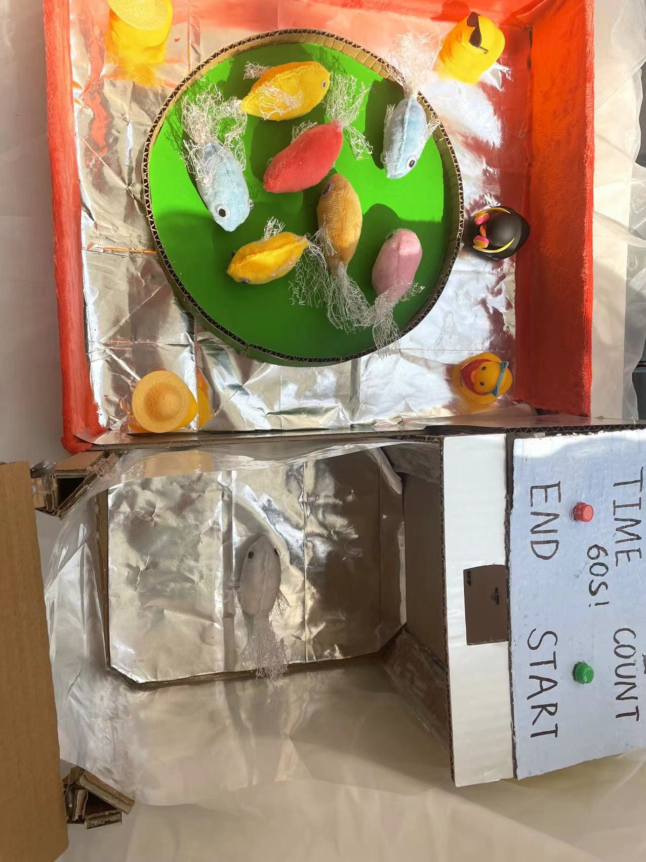
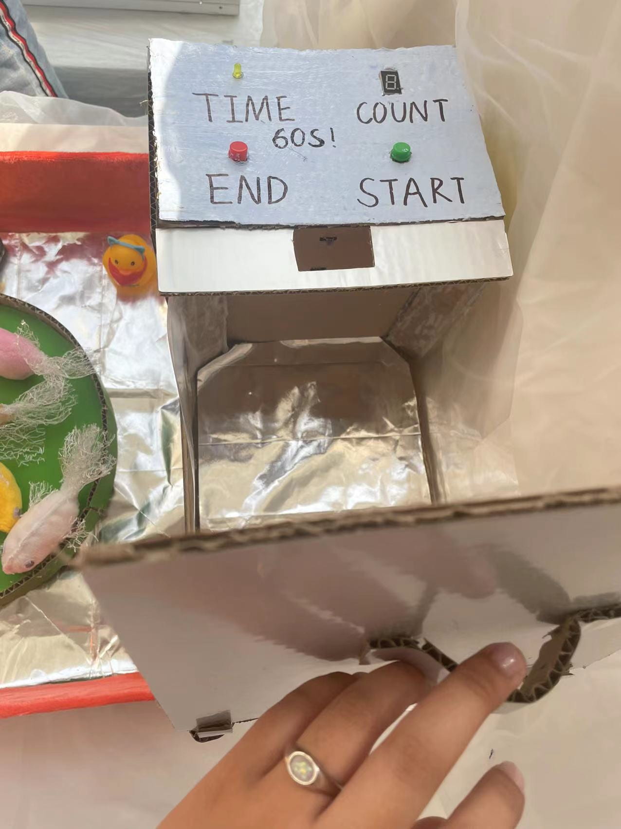
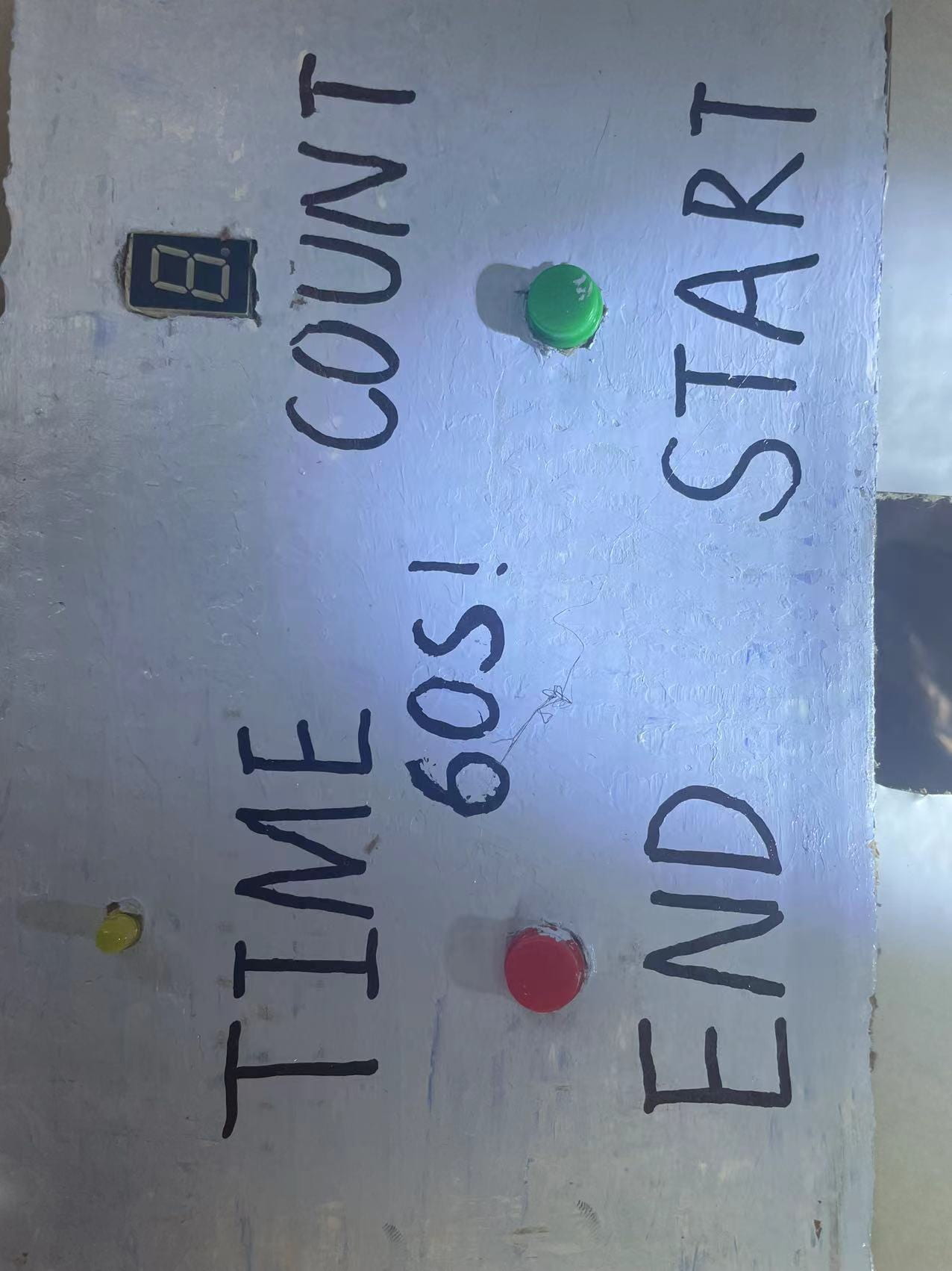
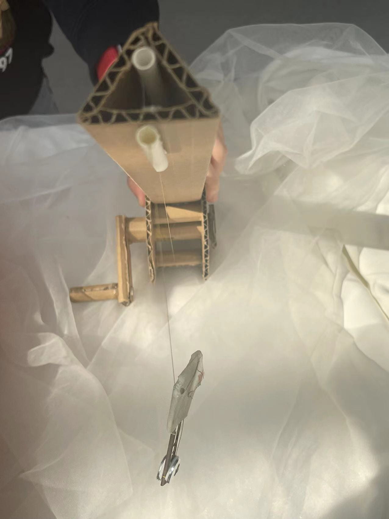
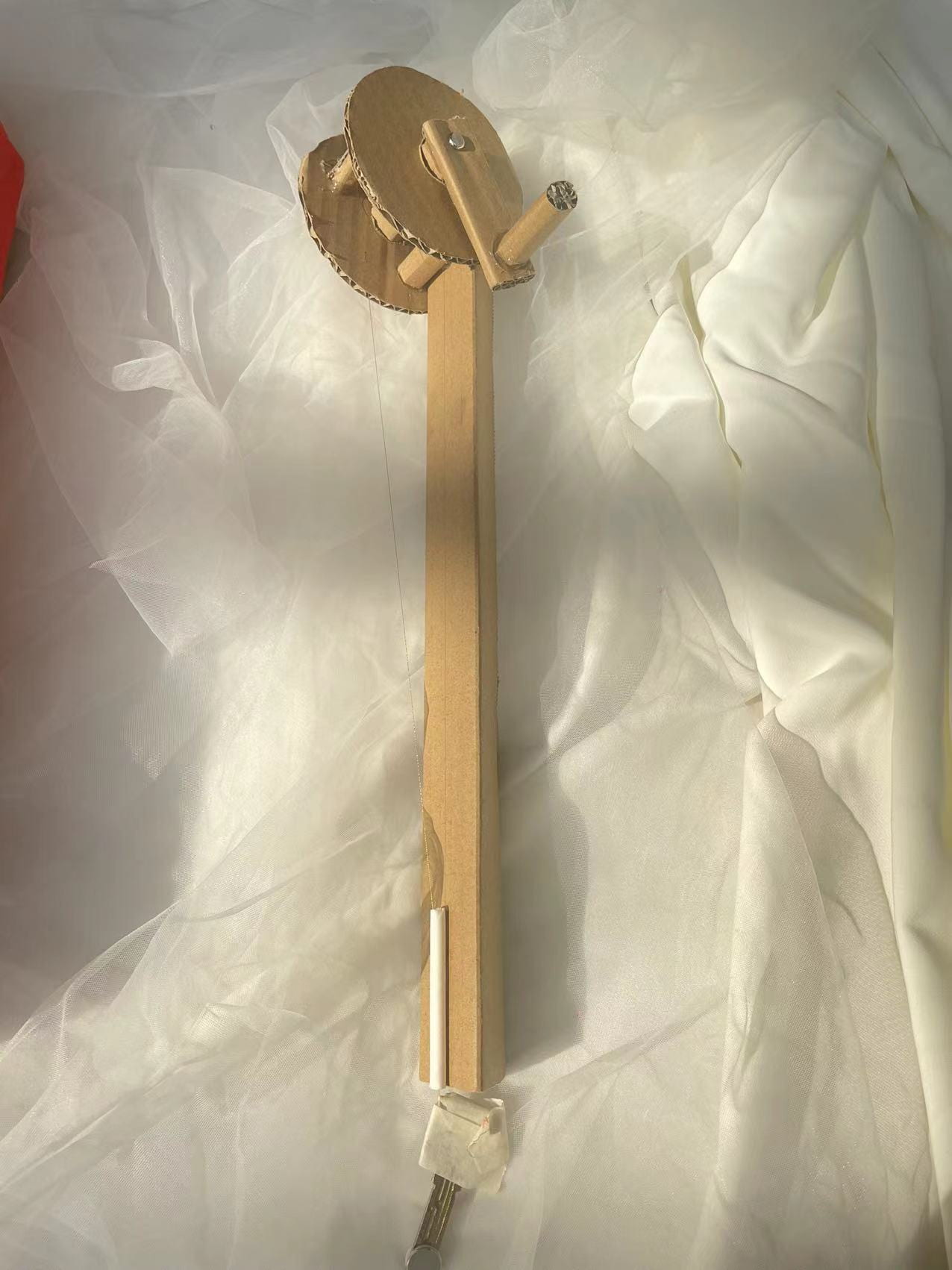
We also included the circuit diagram and the code used for programming the fishing simulator.
The following code is done by Haotong with help from professors:
#include
#include "pitches.h"
Servo myservo;  //

int y = 0;  //resistor of light sensor
int y_n = 0; // the delta of light sensor
int count = 0;
int bottom = 0;       //reset button
int levelBottom = 0;  //stop button
int pos = 0;
int speed = 5;
int flag = 0;// to determine whether the device is running or not

int flag2 = 0;//prevent the counting function from running when one round doesn't finish

int music[] = { NOTE_C4, NOTE_B3, NOTE_E2, NOTE_E2, NOTE_E2, NOTE_E2, NOTE_D2, NOTE_G2, NOTE_E2 };
int noteDurations[] = { 4, 4, 4, 4, 4, 4, 4, 4, 4 };
unsigned long startTime;
unsigned long endTime;

void setup() {
  // put your setup code here, to run once:
  pinMode(12, OUTPUT);
  pinMode(8, OUTPUT);   //8是右亮
  pinMode(9, OUTPUT);   //9右下亮
  pinMode(10, OUTPUT);  //10 上
  pinMode(11, OUTPUT);  //11中间
  pinMode(13, OUTPUT);  //13左下
  pinMode(7, OUTPUT);   //7下
  pinMode(6, OUTPUT);   //6右上
  pinMode(3, OUTPUT);   //time
  Serial.begin(9600);
  myservo.attach(5);
}

void loop() {

  // put your main code here, to run repeatedly:

  if (flag == 1){
    endTime = millis();
  }

  if (y_n == 0) {
    y_n = analogRead(A0);
    y_n = y_n + 120;
  }
  bottom = analogRead(A1);
  levelBottom = analogRead(A2);


  if (millis()- startTime >= 60000 && flag == 1 ) {
    digitalWrite(3, HIGH);
    tone(12, 500);
    delay(2300);
    noTone(12);
    digitalWrite(3, LOW);
    flag = 0;
    startTime = millis();
    //


  }


  if ((bottom > 1000) && (flag == 0)) {
    flag = 1;  //maybe can remove
    startTime = millis();
    y_n = 0;
  }

  if (levelBottom > 1000) {
    flag = 0;
    count = 0;
    y_n = 0;
  }


  pos = pos + speed;
  if (pos >= 180) {
    pos = 180;
    speed = speed * -1;
  } else if (pos <= 0) { pos = 0; speed = speed * -1; } if (flag == 1) { // Serial.print("Servo: "); // Serial.println(pos); myservo.write(pos); } //myservo.write(pos); // tell servo to go to position in variable 'pos' if (bottom > 1000) {

    count = 0;
    flag = 1;
    speed = 5;
  }
  y = analogRead(A0);
  //Serial.println(y);
  Serial.println(bottom);
  if ((((y > y_n)&& (flag == 1)))&&(flag2 == 0)) {
    //digitalWrite(8,High);
    flag2 = 1;
    if (count == 1) {
      tone(12, 300);
      digitalWrite(8, LOW);
      digitalWrite(9, LOW);
      delay(1000);
      //digitalWrite(8, HIGH);
      //digitalWrite(9, HIGH);
      noTone(12);
      delay(800);
    }
    if (count == 2) {
      tone(12, 400);
      digitalWrite(8, LOW);
      digitalWrite(10, LOW);
      digitalWrite(11, LOW);
      digitalWrite(13, LOW);
      digitalWrite(7, LOW);
      delay(1000);
      //digitalWrite(8, HIGH);
      //digitalWrite(10, HIGH);
      //digitalWrite(11, HIGH);
      //digitalWrite(13, HIGH);
      //digitalWrite(7, HIGH);
      noTone(12);
      delay(800);
    }
    if (count == 3) {
      tone(12, 500);
      digitalWrite(8, LOW);
      digitalWrite(10, LOW);
      digitalWrite(11, LOW);
      digitalWrite(9, LOW);
      digitalWrite(7, LOW);
      delay(1000);
      //digitalWrite(8, HIGH);
      //digitalWrite(10, HIGH);
      //digitalWrite(11, HIGH);
      //digitalWrite(9, HIGH);
      //digitalWrite(7, HIGH);
      noTone(12);
      delay(800);
    }
    if (count == 4) {
      tone(12, 600);
      digitalWrite(6, LOW);
      digitalWrite(8, LOW);
      digitalWrite(9, LOW);
      digitalWrite(11, LOW);
      delay(1000);
      //digitalWrite(6, HIGH);
      //digitalWrite(8, HIGH);
      //digitalWrite(9, HIGH);
      //digitalWrite(11, HIGH);
      noTone(12);
      delay(800);
    }
    if (count == 5) {
      tone(12, 700);
      digitalWrite(6, LOW);
      digitalWrite(10, LOW);
      digitalWrite(11, LOW);
      digitalWrite(9, LOW);
      digitalWrite(7, LOW);
      delay(1000);
      //digitalWrite(6, HIGH);
      //digitalWrite(10, HIGH);
      //digitalWrite(11, HIGH);
      //digitalWrite(9, HIGH);
      //digitalWrite(7, HIGH);
      noTone(12);
      delay(800);
    }
    if (count == 6) {
      tone(12, 800);
      digitalWrite(6, LOW);
      digitalWrite(7, LOW);
      digitalWrite(11, LOW);
      digitalWrite(9, LOW);
      digitalWrite(10, LOW);
      digitalWrite(13, LOW);
      delay(1000);
      //digitalWrite(6, HIGH);
      //digitalWrite(10, HIGH);
      //digitalWrite(11, HIGH);
      //digitalWrite(9, HIGH);
      //digitalWrite(7, HIGH);
      //digitalWrite(13, HIGH);
      noTone(12);
      delay(800);
    }
    if (count == 7) {
      tone(12, 900);
      digitalWrite(10, LOW);
      digitalWrite(8, LOW);
      digitalWrite(9, LOW);
      delay(1000);
      //digitalWrite(10, HIGH);
      //digitalWrite(8, HIGH);
      //digitalWrite(9, HIGH);
      noTone(12);
      delay(800);
    }
    if (count == 8) {
      tone(12, 1000);
      digitalWrite(6, LOW);
      digitalWrite(7, LOW);
      digitalWrite(8, LOW);
      digitalWrite(9, LOW);
      digitalWrite(10, LOW);
      digitalWrite(11, LOW);
      digitalWrite(13, LOW);
      delay(1000);
      noTone(12);
      for (int thisNote = 0; thisNote < 9; thisNote++) { tone(12, music[thisNote], noteDurations); delay(400); noTone(12); flag = 0; } } count = count + 1; if ((speed >= 0) && (count > 1)) {
      speed = speed + 2;
    } else {
      speed = speed - 2;
    }


    if (count == 10) {
      count = 0;
      flag = 0;
      speed = 5;
    }

  } else {
    digitalWrite(8, HIGH);
    digitalWrite(9, HIGH);
    digitalWrite(10, HIGH);
    digitalWrite(6, HIGH);
    digitalWrite(7, HIGH);
    digitalWrite(11, HIGH);
    digitalWrite(13, HIGH);
    delay(100);
    flag2 = 0;
  }
  //delay(10000);
}
Initial idea:
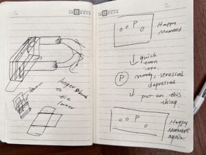
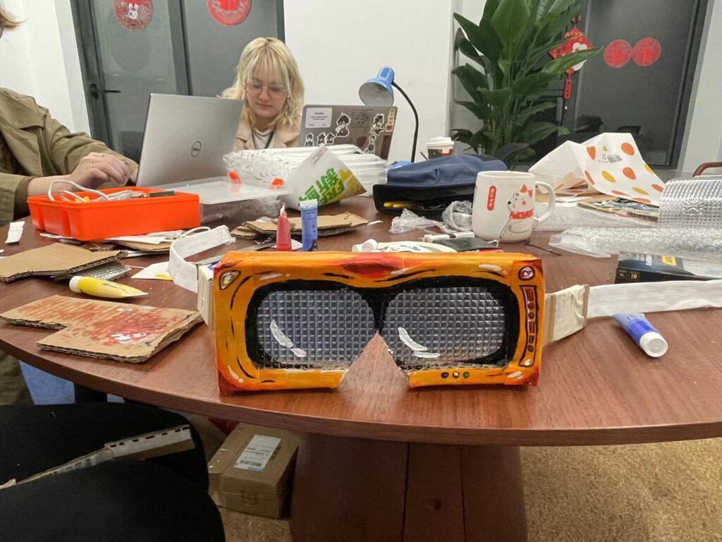
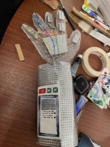
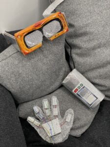
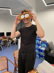
Our initial idea of this project is to creat a device that is able to recreate scence but without risking what happened in The Veldt. So we came up with an idea of creating a pair VR glasses and glove( it provide the sense of touching) instead of a whole room, so that the tragety will not happen in this case.
Its working principle is, when you turn the device on, it will start to record the scene that you want it to store and replay later, and when you want it to do so, you can simply put it back on, and it will re-show you the scene in viewing, listening, and touching.
critical analysis and assessment of a performance of group 1’s perforamce.
Start with the description of the project. How relevant/not relevant is the interactive artifact to the fictional story? How well/not well does it meet the criteria of the assignment? What is your opinion of the design of the device? How creatively does the performance help you understand the artifact? Do you have any suggestions for improvements?
This short performance shows a scene of what it would be like with or without the “subtile showing mask” in the epidemic time in The Plague. It shows how it can avoid misunderstanding and friendly fire situation by using the masks to help the elders to understand what the soldiers were saying. I think it is pretty relevant to the story considering that it is in the background of the story. And it is alsovery creative to print out the subtitle from the mouth part of the masks. And the performance is helpful for me to understand what the “printer” on the mouth is for because before the performance I thought it is just a decoration.
I think it would be better if they don’t seperate the whole story into two situations, which are without and with the masks, because personally I think it makes the performace kind of disengaging by saying “It would different with this new device…”. The officers can directly put the masks on after realising the old guy has hearing problem, which would makes the performance more fluently.
What insights did you gain about this product and how the perception of the artifact has changed over its history?
This “77 steps” was initially designed for the Navy and American army, so it was well-known for its high quality, and load-bearing capacity. And in the 1990s, this chairmaking company shift its market in another direction, into daily using chairs.
What surprised you about this product?
I have seen the “Emeco” style before, and I realized that they were all fake ones after reading this article. I’m very much in favor of the designer’s concept of environmental protection. If a chair is designed with durability in mind, it can reduce a lot of pollution.
Find another artifact that has followed a similar path by deviating from some of its original intent.
Jean: Gold-rush
Nowadays:
Fashion
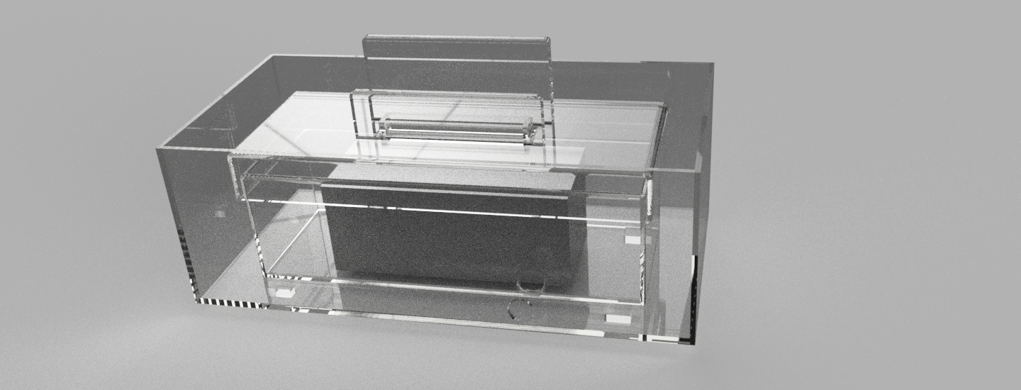
the model of the phone dust cleaner is as below:
this is the model after rendering:
Add background: 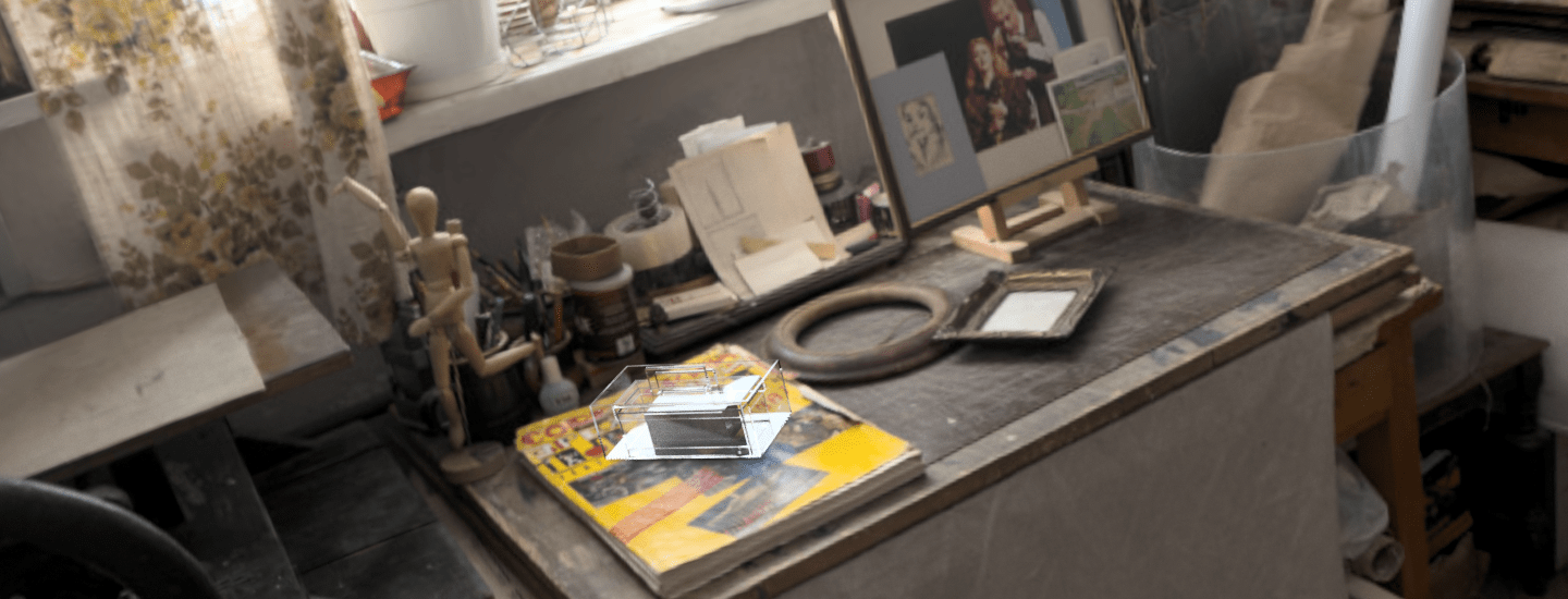
Write a blog post about your learnings and understanding of Industrial design prototyping. Do some research on the future of prototyping and give examples of where you think prototyping will go in the future.
There are multiple roles that prototypes play, in between sketching, after sketching, and helping resketching. Just as it says in the video, “the best prototypes move your design forward”, building a prototype can give you a brief understanding of how the design goes so far, and let you see the problems. While after the stretching, the prototype will show how your final design goes while interacting with real life and customers, thus giving you more ideas about how to improve it.
Here are some tips that I have learned from the video:
-Don’t be afraid to fail. In order to make an idea work, it is possible that we might have to make lots of prototypes.
-By making prototypes, you can test the feasibility of your idea, highlight problems, use them in focus groups for feedback, and refine your design.
-visual appearance model + prototype -> close to finished design. make prototypes before visual appearance models.
-rapid prototyping is not always the best choice. When we are designing big things, it can be hard for us to prototype 1:1
-progress to prototyping as soon as possible.
Future of prototyping:
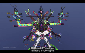
I think there’s a brand new way for rapid prototyping to go: 3D VR drawing
This drawing method can be used in rapid prototyping,

1. Multifunctional bathroom supplies storage rack
It always bothers me that there is no bathroom storage shelf that can actually meet customers’ needs. Take the bathroom in my house as an example, there are all kinds of shelves – towels shelves, toothbrushes shelves, and shelves for dirty clothes. They are designed to save space, but because they all only have one single function, so together they don’t really work well for saving space.
So I want to design a shelf that has multi-functions containing all bathroom cleaning appliances, towels, and personal hygiene products.
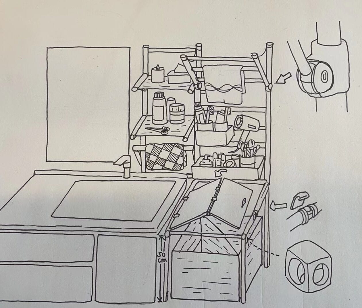
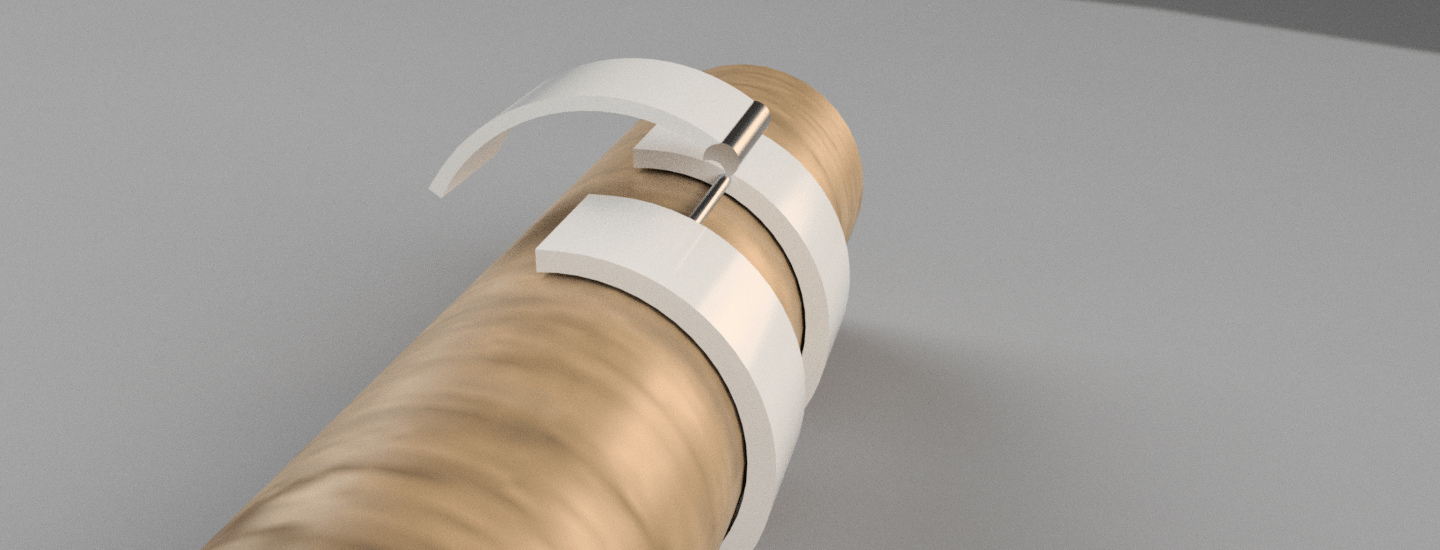
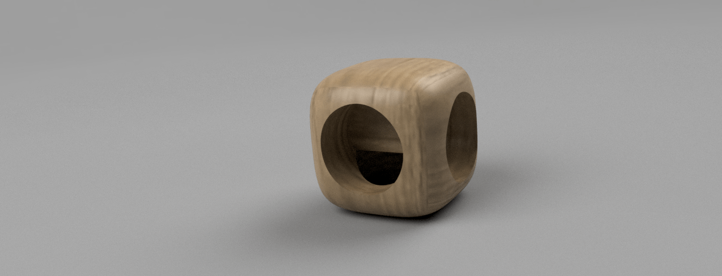
Here are the models of the key components I made in fusion 360
2. Water drinking reminder
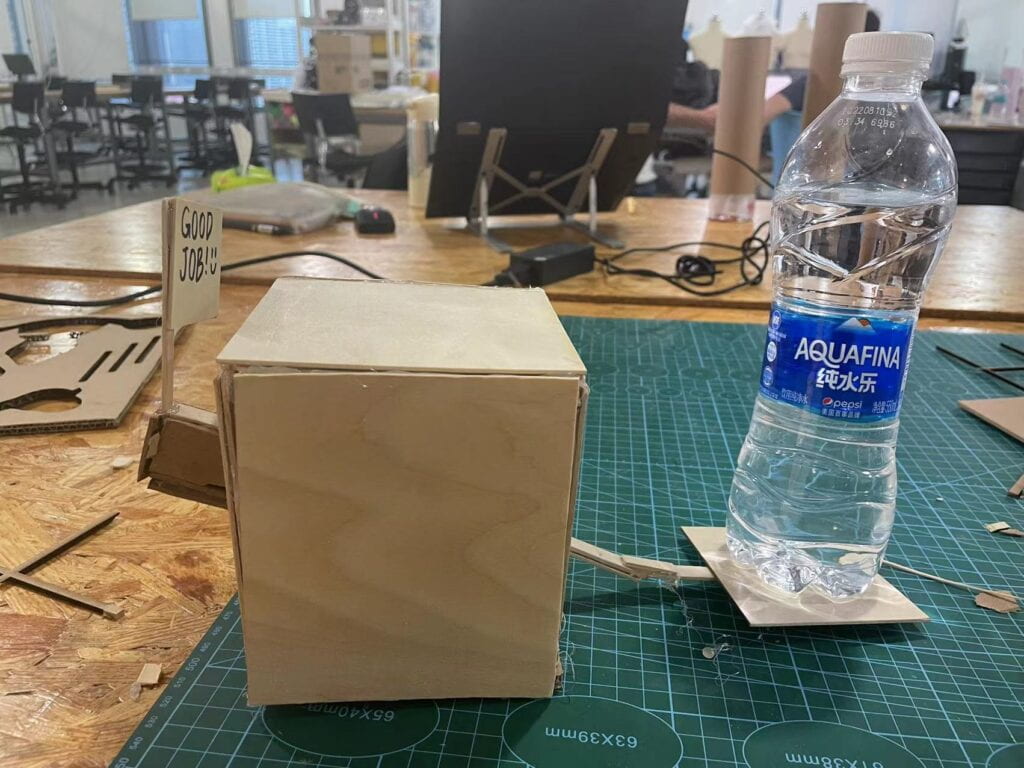
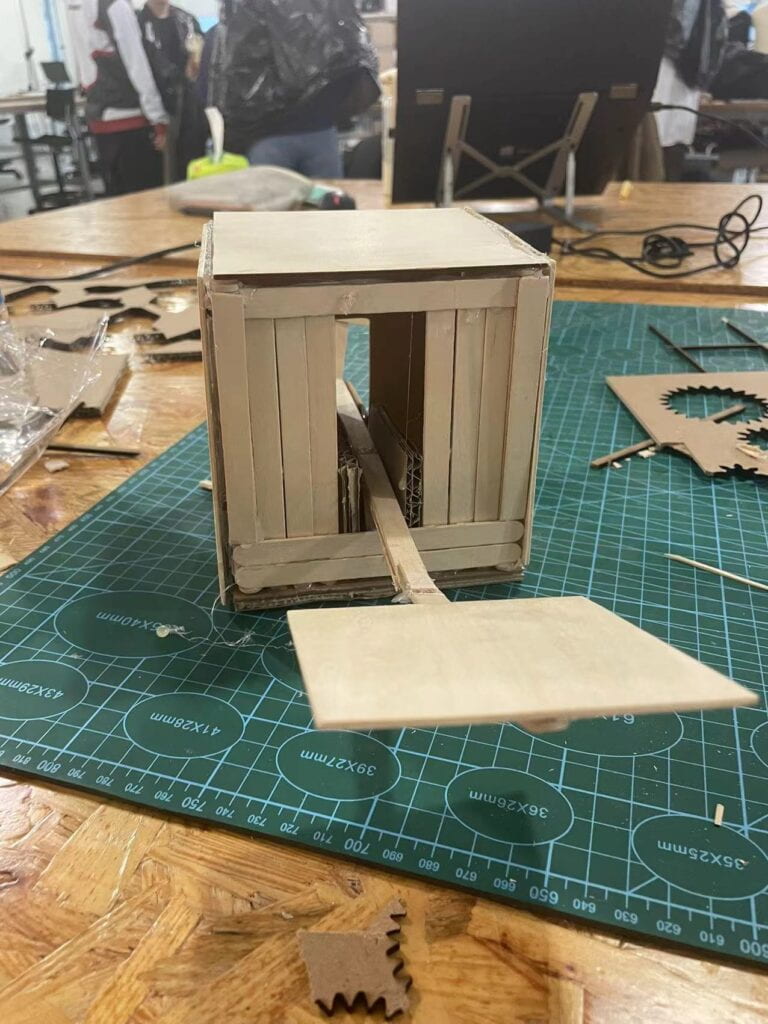
When I am too focused on work, I always forget to drink enough water to stay hydrated. I want to design a coaster that when the mug on it is empty for longer than ten minutes, will raise the alarm music to remind the user to refill the mug and drink more water.
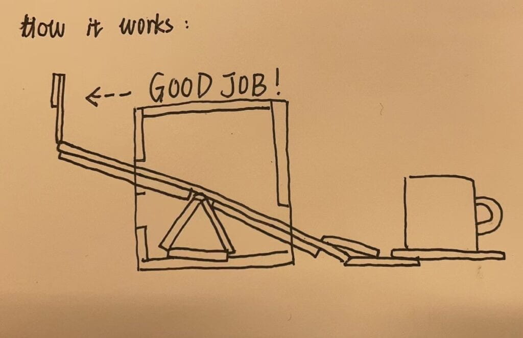
Raw materials: wooden sticks, board, cardboard, and hot glue.
Whenever you put a mug on it, due to the seesaw structure, the “good job” will show to motivate you to drink water more frequently.
Device 2:
Mobile phone dust cleaner
Body 1: Shell
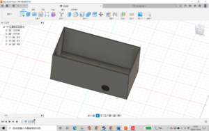
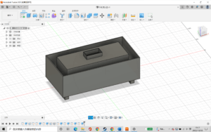
First, I design a shell for the mobile phone dust cleaner, which needs to be able to wrap the blower machine, but also have a certain space for heat dissipation. The hole in the shell is used to let the wires of the blower machine to get out of the shell.
Body 2: Blower machine
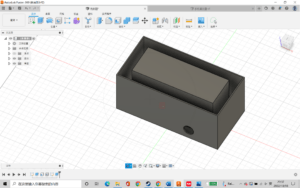
In step two, I build a model of the gray box to represent the blower machine.
Body 3: Socket
Add a small port to the blowing machine to plug in your phone’s charging port.
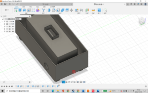
Body 4: Add four feet at the bottom, and done with the sketch of phone dust cleaning machine.
Cardboard bike
It is mind-blowing for me that people can actually ride a bike that is made of cardboard. I was under the impression that cardboard was usually fragile and would be soluble in water. It is impressive that the designer used two strategies to reinforce the bike. First, the cardboard that was used to build the bike is actually folded cardboard, which is three-time stronger than regular cardboard. Second, the body of the bike adopts a diamond shape structure, which evenly distributes the weight of the person to the two wheels.

Nintendo Labo
I think it is a smart idea to use cardboard in children’s toys. Not only is it environmentally friendly, but it also inspires children’s curiosity during the assembly process. Also, cardboard feels different from plastic which is conducive to the development of children’s senses.

Chairigami
Can you imagine furniture made of cardboard? Well, this company called Chairigami makes it possible. They don’t just have basic tables and chairs, but more sophisticated ones like iPad consoles and one-piece tables and chairs. They are all both practical and aesthetic, opening up a new train of thought for household design.

More unconventional materials
Mushroom mycelium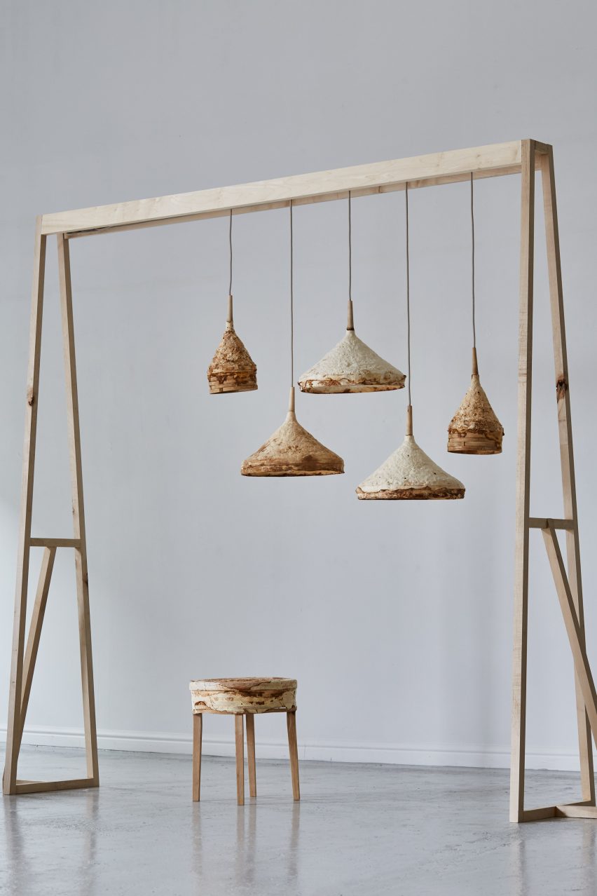
The furniture shown above is designed by Sebastian Cox and Ninela Ivanova. Sebastian, the furniture designer, teamed up with the researcher Ninela to use mushroom mycelium in household design.
Wastewater
The Dutch Water Authorities developed a new technology to reclaim a new sustainable material from wastewater. Designer Nienke Hoogvilient uses this kind of special material to build containers for cremation ashes, named MOURN.

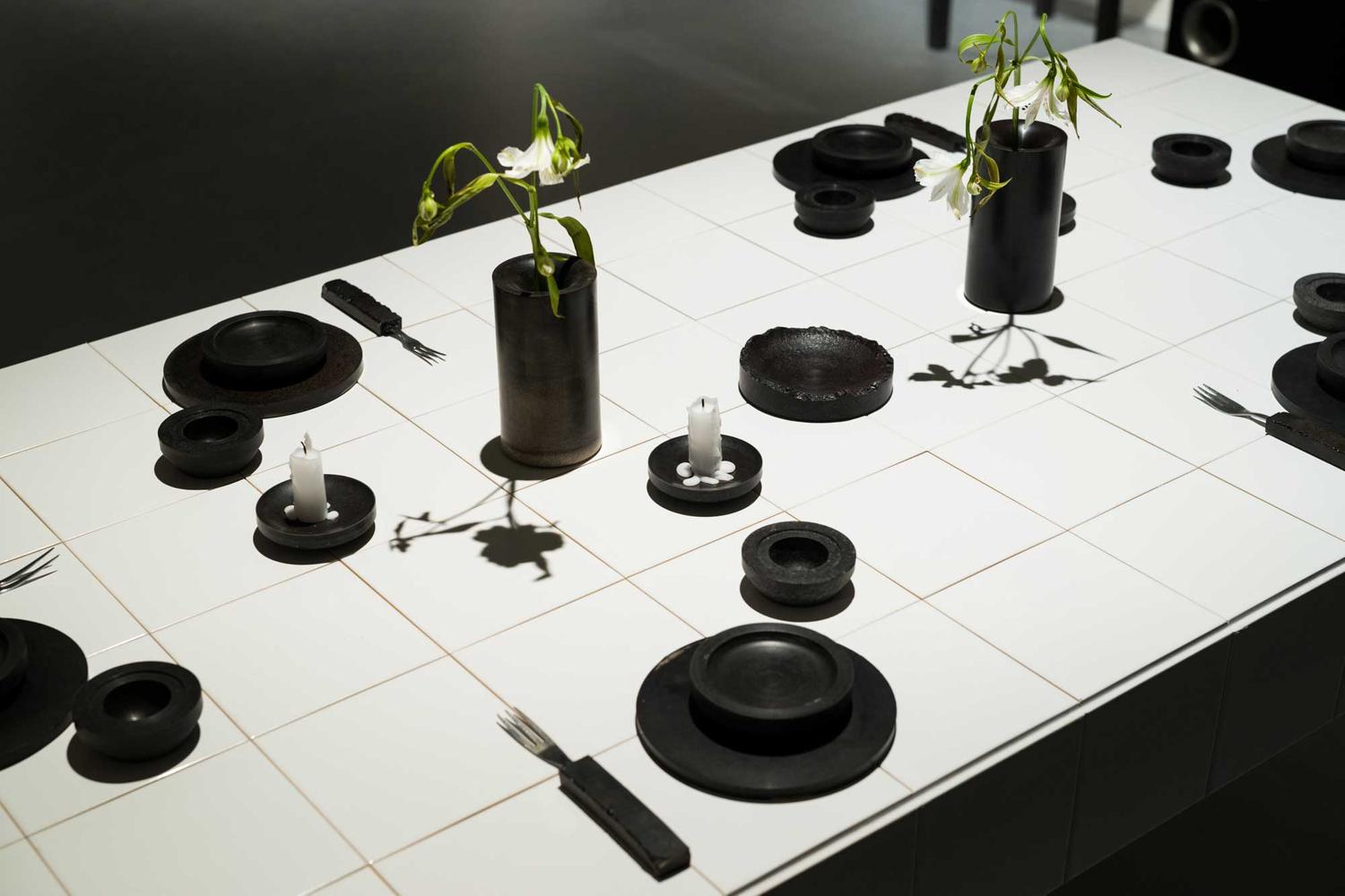
Blood
Designer Basse Stittgen used discarded cow blood to build items
My initial idea is to build a web structure bridge face to disperse the pressure.
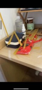
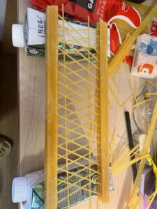
this is the first version of my idea, and after testing it can hold 1.5 kg weight.