LIGHTING CONNECTION – ADRIANA GIMÉNEZ ROMERA – INMI LEE
The interplay between human touch and our body’s biological chemistry is not only intricate but profoundly significant. In an era increasingly dominated by digital connectivity, the tangible essence of human connection has faded. Touch is a catalyst for fostering genuine connection and enriching our well-being. We looked at connection in terms of an emotional and biological superpower, in simple terms, feeling connected, especially through touch, makes us happier. Guided by these insights, our project aimed to rekindle the materiality of human connection.
From the beginning, we knew we wanted to create an interactive art piece, or more specifically an interactive art experience. I took inspiration from SEA THE LIGHT, a project I came across while looking for inspiration. My partner and I loved its aesthetic and began to think about how to tailor it to our initial idea of human connection as well as how to fabricate it.
We took the idea of a human circuit and centered our interaction around it. To allow the flow of electricity, an electrical circuit needs to be closed. Traditionally, we use wires to conduct electricity, however, our bodies are conductive too, and, if we hold hands with someone and at the same time each of us carries one end of the circuit, we would have closed it. If we let go, the circuit would be open, and the flow of electrons would have stopped. This feels like a simple idea, yet, to us, it was quite meaningful, you have to collaborate with someone to be able to see the show of lights, which is a colorful representation of what our bodies experience when we form an emotional and physical bond with someone.
FABRICATION AND PRODUCTION:
We divided our project’s fabrication into several components. First, we worked on the circuit. We wanted to test the feasibility of our concept and experiment with the conductivity of human touch. We followed the following YouTube video and tried to best replicate the circuit. In this process, we attempted to use the Arduino Nano that was being used in the tutorial and ended up having some difficulties with getting our computers to read the microcontroller, we tried several different cables without any luck, so we thought it would be better to adapt the circuit for the Arduino One, that we were already familiar how to use. And this one was already looking more promising.
The video was also extremely helpful in terms of the code and gave me a good outline for tailoring it to our project. I initially coded for the output of the human circuit to be just turning on one LED. Despite this being very simple it was not that straightforward to get it to work. The reading of the values wasn’t very stable and IMA fellow Kevin spent a lot of time helping us solve the issue. Our LED was flashing and the reason why it was cycling between switching on and off so much despite the circuit being closed had to do with three things that we eventually figured out. First, we had to update the reading of the values, so we added a line of code such that “oldReading = reading”. We then increased the threshold to 500, which we continued to update throughout the project, finally, we also tested different capacitors to see which one could make our values rise quicker so that the reaction time between cricuit_open and circuit_closed wouldn’t be too long. However, after two hours of trying, it started to work perfectly using the same capacitor that we had at the beginning.
The human circuit worked well and we were on track with our planned schedule. The next day we switched the LED for 10 NeoPixel strips. This meant updating the code from one output to 10 and adding an external power source. In this step, I coded for the color of each LED to be the same. And we kept it this way for the User Testing, out of time consideration mostly, because we wanted to get started on fabrication, which was the most time-consuming area of our project.
We used a 120×120 cm wood board as the base for our setup. We had to figure out a way to attach the NeoPixel strips to the board without gluing them in place, as well as a way to lift the board a few meters off the ground. Professor Imni suggested we use zip ties to secure the NeoPixel strips. After I had painted the board black, we drilled a series of holes, starting with 10 large-size ones on the ends of the board which would be used to thread through our cables and hide them on top of the board, (hidden on the face looking towards the ceiling). The second group of holes we drilled were much smaller, two holes measured apart by the width of the NeoPixel strip for each zip tie to go through. After securing the strips we worked on the 4 cables that would allow us to hang our structure. Dalin showed us how to make and secure the loopholes on the cables and we got those ready for hanging the project before the user testing session the following day.
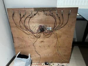
Next, we needed to ideate a way to attach the fiber optics to each LED without gluing them. What we came up with was putting double-sided tape all along the strip and hot glue the fiber optics onto the tape, not the actual strip itself. This was a great solution, on top of avoiding damaging the NeoPixel strips, it made the project’s disassembly much easier since all the fiber optics came out in one go.
Unfortunately, all the fiber optics we had ordered did not come in time for the user testing. So, the effect was not complete, nonetheless, once we had glued the fiber optics we had at hand and had hanged the board, we were both quite pleased with how it was looking thus far.
Another component that we had worked on was sound. This was how we decided to add the communication between Arduino and Processing to our project. I followed the examples for serial communication we had worked on during class and modified the code so that each time the circuit was closed, meaning people were holding hands, a harp sound would play, and whenever the connection was broken, the sound file would stop, this was achieved by a series of boolean and if statements. I ran through a few minor issues trying to establish the connection between Arduino and Processing and IMA fellow Shengli helped me figure out how to solve them. We first created a test code where we checked to see if the file could be played. When we got that to work, we incorporated the boolean statement and if statements into the test code and got the music to stop when the circuit was open. Since Processing was going to be receiving the value 1 for a closed circuit and 0 for an open one, we had to translate that information to Arduino. So, we added the line state = 1; in the case CIRCUIT_OPEN: and state = 0; in the case CIRCUIT_CLOSED: which processing would borrow as initiators for music.play() or music.stop().
The last two components we worked on were creating something for people to hold on to the ends of the circuit and adding curtains. Initially, we were not sure how we wanted to present this. What we ended up doing for the user testing was elongating the two wires and attaching each of them to a wooden stick, (similar to those used in a relay race) which we covered in conductive tape.
USER TESTING:
During the user testing session, we received very critical and helpful feedback. Our main concern was making people hold hands and have it be as intuitive as possible rather than making it obvious or didactic.
The suggestions we received for this issue solved two problems for us. During the user testing, we figured out that the sticks were distracting from our mission, what I initially thought would just be something easy to hold, was taking too much protagonism, someone mentioned the stick resembled a wand and that she thought she had to move it to make the lights magically light up, cool idea, but not at all related to our project.
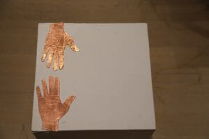
Others suggested making it smaller or turning it into a hand shape. Both my partner Kelly and I thought the hand would be the best option, it was simple, intuitive, and related to touch, perfect! So, we laser cut two hands and repeated the process, solder wires + conductive tape.
Another suggestion we wanted to employ came from Professor Gottfried. He said we could create two entrances, this way the two users/strangers would meet each other in the middle, make eye contact, and perhaps be more inclined to hold hands.
For the user testing, we did not hang the board at the floor-to-board distance that we wanted. Primarily, because of the great effort it takes to raise the board that high. We deemed it enough for testing. However, because of the awkward height that was making people walk into the fiber optics, we received another consideration. How about having people sit down and look up, instead of standing? And what if they are lying down on a yoga mat, like watching the stars on a starry night? We did not consider the laying down idea too much. (We had already used a yoga mat for our midterm project and it might be overdoing it a little bit to do it for the final too). However, we had a lot of back and forth between trying to decide if we wanted the art installation to be fit to stand or sit down. Eventually, we concluded that standing was better, as it would be more convenient to set up the hands that way.
After user testing, we started working on the modifications before mentioned as well as on the final version of the code. My initial hope was for the light display to be much more dynamic than what we presented. I read a few research papers on the biochemistry of touch, interrogated my biology major roommate, and had a few ideas on how to represent the cells and the neural connections formed in our brains when we are receiving wanted personal contact. I wanted the light display to poetically resemble the inside of our body, the chemistry of touch, (in a much simplified and not entirely accurate way, of course). However, my coding skills and tight deadline made us settle for something within my scope of ability, yet, I would argue, still quite interesting and aesthetic: palettes.
I used the FastLED library and followed the following tutorials to code 4 rotating palettes.
When it came to finalizing the fabrication we spent most of our time cutting and hot-gluing each fiber optic onto the LEDs. We used 10 LED strips, each composed of 60 singular addressable LEDs, and per each LED we had around 2 to 4 fiber optics. If you count them up, it’s a lot of fiber optics!
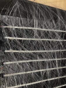
We worked meticulously and patiently, while one of us glued, the other held the fiber optic in place until it was fully dry. However, once we had finished gluing, we had a minor project crisis.
We had two options, have the NeoPixel Strip be part of our design, or cover it.
If we had the strip on show, it would be more evident that the light was emanating from the 10 strips, nothing horrible just a design choice.
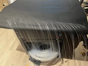
If we covered it by threading each fiber optic through a piece of black paper, there would be no visible lines, we would have a darker room and a completely different effect.
We debated what to do, we tested, what method would allow for the ends of each fiber optic to be brighter, and we did not see any major differences. We had already threaded through one NeoPixel strip, and upon deciding not to continue threading the rest, we decided that instead of getting rid of the paper and wasting our efforts we would thread only the two lateral NeoPixel strips. And so we did.
The final touches included hanging the curtains that would enclose our project and raising the board roughly 2’5 meters above the ground. Special thanks to Dalin, we couldn’t have done it without you! As well as Professor Inmi and Kevin for helping us hang the curtains. (Apologies for the unasked-for workout we put you through!)
CONCLUSION
DISASSEMBLY
APPENDIX
Arduino Code:
#define NUM_OF_VALUES_FROM_PROCESSING 1 /* CHANGE THIS ACCORDING TO YOUR PROJECT */

/* This array stores values from Processing */
int processing_values[NUM_OF_VALUES_FROM_PROCESSING];
int statepin = 13;

// Constants
const byte sensorPin = A0;
const int threshold = 600; //MAYBE PLAY AROUND WITH THIS TOMORROW, SEEMS TOO SENSITIVE
//const byte ledPin = 3; // Define the pin for the LED
int oldReading = 0;
// Enum for device state
enum DeviceState {INITIALISING, CIRCUIT_OPEN, CIRCUIT_CLOSED};
DeviceState deviceState = INITIALISING;

//Neopixel + music
#include <FastLED.h>

#define NUM_LEDS 60  // How many LEDs in your strip?
#define DATA_PIN 1
#define DATA_PIN 2
#define DATA_PIN 3   // Which pin is connected to the strip's DIN?
#define DATA_PIN 4
#define DATA_PIN 5 // There are a few too many, check which ones are actually connected and their position
#define DATA_PIN 6
#define DATA_PIN 7
#define DATA_PIN 8
#define DATA_PIN 9
#define DATA_PIN 10
#define DATA_PIN 11
#define DATA_PIN 12

CRGB leds[NUM_LEDS];
int next_led = 0;    // 0..NUM_LEDS-1
byte next_col = 0;   // 0..2
byte next_rgb[3];    // temporary storage for next color
int state;
//uint8_t paletteIndex = 0;
uint8_t colorIndex [NUM_LEDS];

DEFINE_GRADIENT_PALETTE(orangepink_gp) {
  100,   153, 204, 255,
         90, 225, 0, 255,
         200, 25, 25, 0,
         255, 255, 100, 0
};

DEFINE_GRADIENT_PALETTE(greenblue_gp) {
  0, 0, 20, 160,
  46, 0, 21, 255,
  179, 12, 150, 0,
  255, 0, 25, 245
};

// Gradient palette "healingangel_gp", originally from
// http://soliton.vm.bytemark.co.uk/pub/cpt-city/rc/tn/healingangel.png.index.html
// converted for FastLED with gammas (2.6, 2.2, 2.5)
// Size: 28 bytes of program space.

DEFINE_GRADIENT_PALETTE( healingangel_gp ) {
  0,  94, 156, 174,
  45,  66, 105, 166,
  84, 117, 117, 192,
  127, 173, 124, 156,
  170, 208, 108, 106,
  211, 197, 119, 73,
  255, 210, 221, 123
};

//CRGBPalette16 myPal = heatmap_gp;
//leds[i] = ColorFromPalette (myPal, 160);
CRGBPalette16 greenblue = greenblue_gp;
CRGBPalette16  healingangel = healingangel_gp;
CRGBPalette16 orangepink = orangepink_gp;

void setup() {
  Serial.begin(9600); // Start Serial communication
  //pinMode(ledPin, OUTPUT); // Set the LED pin as output
  FastLED.addLeds<NEOPIXEL, 1>(leds, NUM_LEDS);
  FastLED.addLeds<NEOPIXEL, 2>(leds, NUM_LEDS);
  FastLED.addLeds<NEOPIXEL, 3>(leds, NUM_LEDS);
  FastLED.addLeds<NEOPIXEL, 4>(leds, NUM_LEDS);
  FastLED.addLeds<NEOPIXEL, 5>(leds, NUM_LEDS);
  FastLED.addLeds<NEOPIXEL, 6>(leds, NUM_LEDS);
  FastLED.addLeds<NEOPIXEL, 7>(leds, NUM_LEDS);
  FastLED.addLeds<NEOPIXEL, 8>(leds, NUM_LEDS);
  FastLED.addLeds<NEOPIXEL, 9>(leds, NUM_LEDS);
  FastLED.addLeds<NEOPIXEL, 10>(leds, NUM_LEDS);
  FastLED.addLeds<NEOPIXEL, 11>(leds, NUM_LEDS);
  FastLED.addLeds<NEOPIXEL, 12>(leds, NUM_LEDS);
  FastLED.setBrightness(100);
  for (int i=0; i<NUM_LEDS;i++){
  colorIndex[i]= random8();
  }
}

void loop() {
  getSerialData();
  int reading = analogRead(sensorPin);
  //Serial.println(reading);

  switch (deviceState) { // Correct switch statement syntax
    case INITIALISING: // Correct case statement syntax
      // Perform any initialization tasks if needed
      deviceState = CIRCUIT_OPEN; // Move to the next state
      break;

    case CIRCUIT_OPEN:
      // If reading is less than threshold value, human circuit has been made
      if (reading < threshold) {
        state = 1;
        // Turn on the LED
        //digitalWrite(ledPin, HIGH);
        for (int i = 0; i < 60; i = i + 1) {
          //leds[i] = CRGB(5, 10, 205);
          //leds[i] = ColorFromPalette (myPal, 160);
          leds[i] = ColorFromPalette (greenblue, colorIndex [i]);
          //fill_palette (leds,NUM_LEDS,paletteIndex, 225/ NUM_LEDS,myPal,70,LINEARBLEND);
          //EVERY_N_MILLISECONDS (30){
          /*EVERY_N_MILLISECONDS (15){
            for(int i= 0;i<NUM_LEDS; i++){
              colorIndex [i]++;
            }
            //paletteIndex ++;*/
            EVERY_N_MILLISECONDS (7000){
              for(int i=0; i<NUM_LEDS; i++){
                leds[i]=  ColorFromPalette (greenblue, colorIndex [i]);
              }

          }

             EVERY_N_MILLISECONDS (7000){
            for(int i= 0;i<NUM_LEDS; i++){
             leds[i] = ColorFromPalette (healingangel, colorIndex [i]);
            }
            //paletteIndex ++;
          }
          EVERY_N_MILLISECONDS (4000){
            for(int i= 0; i<NUM_LEDS; i++){
            leds[i] = ColorFromPalette (orangepink, colorIndex [i]);
            }
          }
          FastLED.show();
        }
        // Send signal to Processing
        Serial.println("1"); // Signal Processing that LED is on
        // Optionally, perform any other actions you want
        // For example, you might want to print a message via Serial
        //Serial.println("Circuit Closed");
        delay(100);
      }
      else {
        deviceState = CIRCUIT_CLOSED; // Move to the next state
      }
      break;

    case CIRCUIT_CLOSED:
      // If reading is more than threshold value, human circuit has not been made
      if (reading > threshold) {
        state = 0;
        for (int i = 0; i < NUM_LEDS; i = i + 1) {
          leds[i] = CRGB(0, 0, 0);
          FastLED.show();
        }
        // Turn off the LED
        // digitalWrite(ledPin, LOW);
        // Optionally, perform any other actions you want
        // For example, you might want to print a message via Serial
        //Serial.println("Circuit Open");

        delay(100);
      }
      else {
        deviceState = CIRCUIT_OPEN; // Move to the next state
      }
      break;
  }
  Serial.println(state);
  //Serial.println(digitalRead(13));
  oldReading = reading;
}

void getSerialData() {
  static int tempValue = 0;  // the "static" makes the local variable retain its value between calls of this function
  static int tempSign = 1;
  static int valueIndex = 0;

  while (Serial.available()) {
    char c = Serial.read();
    if (c >= '0' && c <= '9') {
      // received a digit:
      // multiply the current value by 10, and add the character (converted to a number) as the last digit
      tempValue = tempValue * 10 + (c - '0');
    } else if (c == '-') {
      // received a minus sign:
      // make a note to multiply the final value by -1
      tempSign = -1;
    } else if (c == ',' || c == '\n') {
      // received a comma, or the newline character at the end of the line:
      // update the processing_values array with the temporary value
      if (valueIndex < NUM_OF_VALUES_FROM_PROCESSING) {  // should always be the case, but double-check
        processing_values[valueIndex] = tempValue * tempSign;
      }
      // get ready for the new data by resetting the temporary value and sign
      tempValue = 0;
      tempSign = 1;
      if (c == ',') {
        // move to dealing with the next entry in the processing_values array
        valueIndex = valueIndex + 1;
      } else {
        // except when we reach the end of the line
        // go back to the first entry in this case
        valueIndex = 0;
      }
    }
  }
}
Processing Code:
import processing.serial.*;
import processing.sound.*;

Serial serialPort;
SoundFile music;
boolean isPlaying = false;

int NUM_OF_VALUES_FROM_ARDUINO = 1;
int arduino_values[] = new int[NUM_OF_VALUES_FROM_ARDUINO];

void setup() {
  size(500, 500);

  // Load the sound file
  music = new SoundFile(this, "harp.mp3");

  printArray(Serial.list());
  // Put the name of the serial port your Arduino is connected
  // to in the line below - this should be the same as you're
  // using in the "Port" menu in the Arduino IDE
  serialPort = new Serial(this, "COM12", 9600);
}

void draw() {
  background(0);

  // Receive the values from Arduino
  getSerialData();

  // Play or stop the sound file based on the value received from Arduino
  if (arduino_values[0] == 0) {
    if (isPlaying) {
      music.stop();
      isPlaying = false;
    }
  } else if (arduino_values[0] == 1 && !isPlaying) {
    music.play();
    isPlaying = true;
  }
}

void getSerialData() {
  while (serialPort.available() > 0) {
    String in = serialPort.readStringUntil('\n');
    if (in != null) {
      in = trim(in); // Remove whitespace
      arduino_values[0] = int(in); // Convert string to integer
      println("Received from Arduino: " + arduino_values[0]);
    }
  }
}


