A. “MURAL MARATHON!” – Nicole Cheah – Andy Garcia
The Project From All Angles:

B. CONCEPTION AND DESIGN
In terms of the development of our project’s concept and how previous preparatory research + the essay lead to its final formation: Our project’s development was extremely dynamic– what I mean by this is that we had to tweak our project numerous times throughout the building process depending on what code worked for us, what materials worked for us– and with this, what mechanisms worked for us. The initial concept of our project was thoroughly developed in the “Three Ideas” and “Project Proposal Essay” Assignment. After completing the “Three Ideas” Mini-Assingment, my partner Eric Jiang and I looked at both of our submissions and decided to use one of my designs (at the time I called it the ‘Virtual Graffiti Wall) that I created (see attached below of what I wrote and handed in). After choosing our favorite design along with a few others, we had a meeting with Andy (see attached below notes from meeting with Andy) and we three consulted each of our ideas (including our main one) and discussed how we could best flesh out the idea and bring it to life– this ‘bring to life’ implying how to source materials and incorporate materials and code together to create a moving mechanism. After meeting with Andy, we revised the concept and created new concept drawings (also attached all the concept drawings from Three Ideas and Project Proposal Essay) and submitted these as our Project Proposal Essay. My initial idea for this project was a virtual graffiti wall where users can ‘paint’ onto a projected large wall using ‘light pens’ or simply using their finger (through light tracking + digital painting). I thought, at the time, and also based off of research, the way we could incorporate Arduino + Processing would be how: a) Arduino would track the position and movement of the light pens / fingers while b) Processing would help render on the ‘paint’ (‘paint’ is in quotation marks as there won’t be actual paint on the wall, it is like what we did in the Etch-a-Sketch exercise on Nov.10 recitation but much more largescale) on the wall. Additionally, I really was inspired by a pop-up exhibition at K11 (mall in Shanghai) where it was a dynamic collective art-piece on a wall where everyone could draw on it and sign their signatures (see link attached below). My idea, as expressed in the Three Ideas and Project Proposal Assignment was that Eric and my project would kind of be like a memory of the “IMA 2023 show”– I thought that not only would this be a meaningful cumulative art piece but also can help users or whoever is interacting with our project to destress and have fun with others as mental health is a big thing to consider at the time of our IMA show (which was during Finals week). Things that changed from meeting with Andy– that we realized were more ‘feasible’ to do in real life were using ultrasonic sensors (to help calibrate the position / distance of the spray can– at that time we didn’t even know that we were going to use a spray can, we thought it was going to be like a ‘light pen) and pressure sensor on the tip of the then-decided-on light-pen. I think the way in which we also wanted to make it more interactive was to add paint buckets on the left side of the Processing canvas– that was our initial idea, but in the end, we decided upon using 10 sensors in total: 5 buttons, 2 NeoPixel Strips, 2 Ultrasonic (distance) sensors, and 1 pressure sensor.
I think throughout deciding upon how we were going to put together and make our project work, we constantly thought about how our users are going to interact with our project and how can we elevate this experience + perhaps add more interactive components. With this being said, I think thinking about things like this really influenced our design decisions. As, in the end, we used 10 sensors in total– each triggering all the user’s senses (not really for ultrasonic sensor as it is only calibrating the distance for the spray can, but with every other sensor it did as: neopixel triggers vision because of colour, you can hear police siren sound in the background, you press on the pressure sensor to draw and you can see it on the screen, and then you can press the five buttons with left hand to change colour, clear screen, and take screenshot). I recall clearly, whenever we accomplished something– for example, we got our ultrasonic sensor AND our pressure sensor to work together– the LA’s, Andy, and Kevin would encourage us to look at other ways we can elevate our project. With this, I think Eric and I did quite a bit of reflection during these stages to see what else we could add to our project and ultimately, all of these little improvements we made helped us craft our narrative and shape the story we were trying to tell with our project. You can see how it changed with how the concept went from originally being a collective drawing ‘memory’ board to more of a ‘Mural Marathon’ Graffiti + Police experience!
The User Testing Session was incredibly important to us as we were able to a) get direct feedback from user testers in regards to areas they believe can be improved + b) hear what they think regarding how our functions were working then. I asked my boyfriend, Brian Kwok (CO ‘2024) to be our official user tester and two main feedback points he gave included: a) perhaps incorporating a visible cursor on the screen to make it more clear where every stroke starts and b) maybe add a cap or like a cardboard bit to the top of the spray can for more satisfaction when pressing the ‘spray can’ button. The rest of our ‘user testing notes’ are attached below for your reference. However, I think after a lot of people came around and tested our project, the main feedback points that Eric and I believed we had to focus on after the session were: a) change the wall (which at the time of user session was plain, refer to Appendix to see) to be a brick wall so that users can feel like they are immersed in an alleyway spraying graffiti, b) Andy brought up maybe users can wear something to feel as if they are being rebellious and painting graffiti while being chased by police, c) wrap up the wires to make them look more neat / refined, d) and perhaps find a way to screen-capture one’s drawings after they finish using our project (at the time of user-testing, we didn’t have this function yet). Everything that we implemented post user-testing up till final presentation day / IMA show (note: not many major changes were made in between the presentation day + IMA show time frame) really made our project the experience we wanted to create– which was the feeling of freely painting on a wall with graffiti while being chased by police! I think at the time of user-testing I was a bit confused and was proposing to Eric + Andy whether we should make it into a game (points system) with the whole graffiti + police idea. However, Andy suggested that we keep it as an experience. Now reflecting upon this post-IMA show, I think this was a really good idea as at the IMA show many little kids or even adults who came to play with our project didn’t feel the rush or pressure to draw something. Instead, they took their time to curate something they liked or thought looked good!
INITIAL STAGES: We decided to use one of my ideas that I submitted (Design #3) from the ‘Three Ideas’ Assignment: In this step I was able to brainstorm certain concepts I wished to further explore at the time–

INITIAL STAGES: Our Initial Inspiration (Click the Link to See the Video!) https://drive.google.com/file/d/1dJWCYSUDtOReAx4dh1v6FhjYYusD-hc5/view?usp=sharing
CONSULTING THE IDEA WITH ANDY: Notes from Meeting with Andy–

POST-MEETING WITH ANDY: Concept Sketches / Drawings We Decided Upon–

POST-MEETING WITH ANDY: The Workflow We Decided Upon and Subsequently Created For Our Final Project–

Our User Testing Comments / Problems (Notes)–

C. FABRICATION AND PRODUCTION
I think the biggest challenge we had right from the very start was re-mapping the project constantly– this re-mapping function involved constantly calibrating our ultrasonic (distance) sensors. We had to– in the first place, learn how to code as this class was Eric and my first time coding and actually putting the skill into practice. Even though this was extremely challenging, we constantly referred to slides regarding how to put together a code and eventually we got started with our Arduino main code (the full code which is attached at the very bottom of this report). For the ultrasonic sensor, we had to figure out how to bring the “virtual mouse x and mouse y concept” to life– into physical components. Through a lot of trial and error we were able to figure out how to bring it to life and realized that– for example, we needed a table as our base, and we needed to create a wall (which we ended up creating from cardboard) on the left hand side to mimic the x and y axis in real life (and which the signals can bounce off of, as that is how both ultrasonic sensors communicate and work). After figuring out how to use the ultrasonic sensor, we moved onto digital fabrication and used a) 3D printer to print a spray can which we used TinkerCad program to alter the dimension and b) laser cutter to create a wooden box which we can hide all of our wires + our two arduino unos + breadboard in (design for wooden box was tweaked using the Cuttle.xyz program). After we retrieved what we made from the 3D printer (the spray can) and laser cutter (wooden box) we then moved onto figuring out how to use the pressure sensor– as this was supposed to act as the spray can’s button (what is triggering the painting feeling). After having both our ultrasonic sensor and pressure sensor installed (and codes combined already), we spent a lot of time (a few hours everyday leading up to the user-testing session) to locate the computer in a fixed space (on a table, with the wall we constructed on the left hand side) and just tested the drawing function constantly. Please refer to the Appendices section down below to see videos of this process in particular.
Like mentioned before, since we encountered more success than failures in terms of figuring out how to use our main sensors– which we actually figured out way faster than what we expected (as we are beginner coders)– we kept reflecting on our production choices and revising them (ex: adding new sensors + components, which helped change the narrative as a whole in the end). In the end we used 10 sensors in total, like mentioned above (2 ultrasonic sensors, 1 pressure sensor, 5 buttons, and 2 LED Neo-pixel strips). The criteria we used to pick these sensors were based on a) whether they fit into the story / experience we are trying to show and best present and b) whether they trigger a certain sense (touch, sound, sight, etc…)– as triggering different senses, we discussed, could help make our project more interactive and unpredictable. The sensors we chose were decided upon the day we met Andy for our session where we discussed what ideas we had in mind. Originally, from doing simple research on the internet, I was a bit lost in terms of what sensors could actually make this project work using the sensors / materials available at school’s lab. However, after discussing it with Andy, we realized that using ultrasonic sensors + pressure sensor would definitely be best suited to how our project functions. Looking back, I do not think we played with that many options, as like I said before, we decided upon which sensors we were going to use the day we met with Andy– however, thinking back to a time like this– I remember we changed the way we were going to let users ‘change colours’ from implementing paint buckets in Processing (which users can tap in real life) to using external buttons that were wired into our Arduino Uno.
In terms of this being a jointly-developed project, Eric and I split our time in the lab and on working on the project very equally. The strategy we had throughout the time we were given to work on it was to just figure every step out together as we both had just learned coding from this class starting this semester. I think this was extremely effective and that our hard work paid off in the very end. Moreover, I think the time-management approach we took with this project was similarly extremely effective as we started really really early in the week (many days ahead of user testing / the schedule in general) and everyday spent a few hours working on different components of the project + testing it (trial-and-error, especially with the ultrasonic sensor and pressure sensor function). Since we took this approach with our time-management, we did not need to rush before any major deadline (user testing; final presentation day; IMA show) and we always had our code figured out and working as we tested our project so much. In addition to this cooperation aspect, I just wanted to add that despite not knowing Eric before working with him on this project, it was overall a super fun experience working together. I think I was a bit scared to take on the final project as I was not able to be in the same group as my midterm project (being with friends I already knew outside of class: Tammy and Jess). However, working with Eric over the last month on this project was refreshing and I think we can both say we learned a lot and grew from working with each other!
D. CONCLUSIONS
I think to sum it all up– I feel like this final project was really rewarding as I felt like I was able to apply every skill I learned throughout the semester into one project. I think what was super valuable to me after finishing this project was just the confidence boost I had and ‘Wow, I can really do it’ mindset I had. I have always told myself I cannot code as I have just always thought I am super weak in coding without having ever tried it before. Despite feeling really lost at times during the project, for example when I could not figure out a code for the life of me– I feel like now, post-IMA show + reflecting upon the final project in its entirety, can say that it was really refreshing and rewarding doing this type of project at school. I say this because– with my major being finance, most of the work I have to do is very monotonous like group projects and presentations. This class really taught me step-by-step all the way from which strips on the breadboard is positive and which is negative all the way to having to apply all the concepts we learned on my own– this was really incredible to me.
With that being said, I am really proud of my final project and believe that it definitely aligns with my definition of interaction which I established way earlier on in the semester. My project –like what I mentioned in the mini-assignment on what I define interaction as– both requires time and effort. If you do not spend time trying to figure out how to use the spray can, you will not be able to grasp the full interaction. You need to take your time and figure out how to use the spray can, listen to the police sirens, figure out how to change colors, and just have a fun time drawing.
Our audience on IMA presentation day were extremely interested and engaged– because of this, they interacted with our project exactly how we hoped they would from the start. Little kids playing with our project made it feel even more rewarding as seeing them go up to their parents and show them what they drew, made me feel really happy on the inside (scroll way down to see videos below in Appendices section!)
I think that if I had the chance to further improve this project, like what Andy said on our final presentation day– we could consider a) making it large-scale, making it similar to drawing on an actual wall, and b) implementing a ‘pssffhhhh’ sound to imitate what a spray can really sounds like. In terms of what value I have learned in terms of setbacks and failures– I don’t think we encountered too many, as mentioned before– however small hurdles we encountered such as figuring out the re-mapping taught me about pure perseverance and that anything is possible (like coding, in the case of this situation) if I put time and effort into working on it.
The goals Eric + I wrote about in our Project Proposal Essay Assignment:

E. DISASSEMBLY 🌏
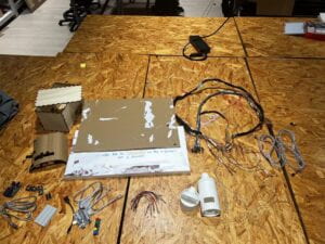
Photo Showing the Disassembly of Our Project: Broke it down into elemental components so they can be recycled and used again by future Interaction Lab Students! 🙂
F. APPENDIX
Complete Materials List:
- 1x Duct Tape– to wrap up wires to make it look neater at the end of the project
- 1x Normal basting tape to mark on the table the dimensions the user has to stay within when using the spraycan
- Jumper Cables–both M-M and M-F
- 5x buttons (with extensions on them)
- Printer so that it can be used to print the ‘brick wall’ images
- 2x LED Neo-Pixel strips
- 3x pieces of white printer paper that can be used to create the title page and instructions page
- 1x medium styrofoam board
- 1x medium / large cardboard board
- Laser Cutter to make a wood box to hold arduino uno + breadboard + all the extra wires (box is meant to help make the set-up look neater along with the duct tape that wraps around all the external wires that are out of the box)
- 2x Arduino Uno
- 1x Breadboard
- 3D Printer to make Spray Can
- 2x Ultrasonic (distance) Sensors
- 1x Ruler / Tape Measure to help in the re-mapping stage of the project
- 1x Pressure Sensor
- 1x Box cutter / pen-knife
- Scissors
- 1x Computer Stand + 1x Laptop (ideally with 3 plug-ins if using projector; if not using projector, computer only needs 2 plug-in ports)
- 1x Sharpie
- 1x USB-C to USB adapter cord (from TaoBao)
Additional Images and Videos:
Prototype (Pre-User Session)– Wiring (with lots and lots and lots of soldering!) + Building the Base (you can see our Cardboard Prototype of the Spray Can in the videos)!

Figuring out how to Re-Map (Pre-User Session): For the 2 Ultrasonic (Distance) Sensors we used in the 3D Printed Spray Can Bottle
Digital Fabrication (Pre-User Session): a) Using the 3D Printer to Make our Spray Can!
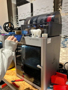
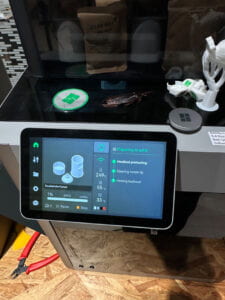
Digital Fabrication Pt. 2 (Pre-User Session): b) Using the Laser Cutter to make a Wooden Box to contain all of our Wires + Arduino Unos (2 of them in Total) + Breadboard
Putting it All Together (Still Pre-User Session)– Figuring out the ‘Set-Up’ + Lots of Re-Mapping to Make the ‘Draw’ Function Work (bringing the concept of ‘mouse x and mouse y) into real life / physical mouse x, mouse y)– Lots of Trial and Error in this Step! Frustrating and Confusing at the start, but was incredibly rewarding at the end when it all worked out~
Positioning of Ultrasonic Sensors (bottom sensor cannot be seen clearly in the two images, but the ‘Y-Axis’ one can be) and Pressure Sensor + Our 3D model of our Spray Can

User-Testing Day!
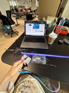
Adding the LEDs (Post User-Testing)
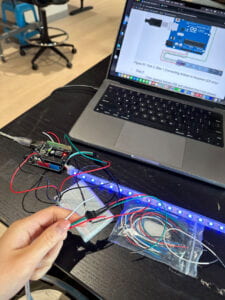
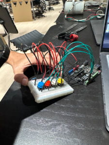
Adding Buttons (Post User-Testing): So that Users can a) change colours, b) take screenshots when they want to ‘save’ their drawing after interacting with our project, c) ‘reset’ the Processing canvas
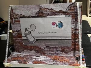
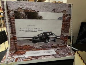
Our Brick Wall That We Made (Post User-Testing): You can see the LEDS that flash ‘Police-Siren’ lights (Red + Blue) on both sides (R+L) and the title page saying ‘Mural Marathon’ and the instructions side
Final Presentation Day In-Class!
IMA Show– so many people and small kids came to test out our project– was so rewarding to see our project working and people (especially small kids) having fun with what we built!
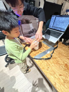
Finally, Our Set-Up on Photoshoot Day!


The Full FINAL CODE We Used For Our Project (3 codes in total; 2 arduino, 1 processing)
*Notes before running code:
- For processing, in order for the code to run, we had to make sure we clicked ‘save as’ to save the processing sketch to ‘Desktop’ before running the code. Then, we put the concrete wall image + police siren sound in a new folder ‘data room’ before running the code. We had to make sure both files are spelt correctly (ex: “Police Siren Ambience in Busy City.mp3” and “concrete wall.png”) as the code would not work if it wasn’t spelt correctly. Refer to the two images below in regards to what I am talking about.
- If using projector: we had to make sure a) the projector is 25-30 cm away from the left wall to the left edge of the macbook, and b) that the projector is sitting on top of the laser cutting board


FIRST ARDUINO CODE –> (1/2 arduino code– this is the MAIN code controlling majority of the sensors)
*Note: As we had two Arduino codes running at the same time, we always started running this one first, and then subsequently the second code. Note that this code pasted below is the ‘main code’ of our project– so the code controlling the 2 ultrasonic sensors, 5 buttons, and pressure sensor.
SECOND ARDUINO CODE –> (2/2 arduino code– this is the LED code)
*Note: This is the second code we ran (again, both run at the same time during presentation mode). This code is our LED code. We knew this code was working when one side of the LED was flashing red light, and the other side flashing blue– just like a police siren!
/// @file ArrayOfLedArrays.ino
/// @brief Set up three LED strips, all running from an array of arrays
/// @example ArrayOfLedArrays.ino
// ArrayOfLedArrays – see https://github.com/FastLED/FastLED/wiki/Multiple-Controller-Examples for more info on
// using multiple controllers. In this example, we’re going to set up three NEOPIXEL strips on three
// different pins, each strip getting its own CRGB array to be played with, only this time they’re going
// to be all parts of an array of arrays.
#include <FastLED.h>
#define NUM_STRIPS 2
#define NUM_LEDS_PER_STRIP 60
CRGB leds[NUM_STRIPS][NUM_LEDS_PER_STRIP];
// int next_led = 0; // 0..NUM_LEDS-1
// byte next_col = 0; // 0..2
// byte next_rgb[3]; // temporary storage for next color
// For mirroring strips, all the “special” stuff happens just in setup. We
// just addLeds multiple times, once for each strip
void setup() {
// Serial.begin(115200);
// tell FastLED there’s 60 NEOPIXEL leds on pin 2
FastLED.addLeds<NEOPIXEL, 8>(leds[0], NUM_LEDS_PER_STRIP);
// tell FastLED there’s 60 NEOPIXEL leds on pin 3
FastLED.addLeds<NEOPIXEL, 7>(leds[1], NUM_LEDS_PER_STRIP);
}
void loop() {
for (int i = 0; i < NUM_LEDS_PER_STRIP; i++) {
leds[0][i] = CRGB::Red;
FastLED.show();
leds[0][i] = CRGB::Black;
delay(1);
}
for (int i = 0; i < NUM_LEDS_PER_STRIP; i++) {
leds[1][i] = CRGB::Blue;
FastLED.show();
leds[1][i] = CRGB::Black;
delay(1);
}
}
PROCESSING CODE –> (only used ONE processing code)
*Note: In addition to the notes above (right under the start of the code section) it is also important before running this processing code to a) make sure both (two in total) wires are plugged into the computer that is running all the codes,(if using projector, there should be three plugs in total)– also must b) make sure port is correct (ex: 1101 is 101)– change in Processing accordingly.
import processing.serial.*;
import processing.sound.*;
Serial serialPort;
SoundFile sound;
// declare an Amplitude analysis object to detect the volume of sounds
Amplitude analysis;
int NUM_STRIPS = 2;
int NUM_LEDS = 60; // How many LEDs in your strip?
color[][] leds = new color[NUM_STRIPS][NUM_LEDS]; // array of one color for each pixel
PImage brickwall;
int NUM_OF_VALUES_FROM_ARDUINO = 8; /* CHANGE THIS ACCORDING TO YOUR PROJECT */
/* This array stores values from Arduino */
int arduino_values[] = new int[NUM_OF_VALUES_FROM_ARDUINO];
float oldx;
float oldy;
void setup() {
//size(1400, 800);
fullScreen();
//background(255);
frameRate(30);
brickwall = loadImage(“concrete wall.png”);
image(brickwall, 0, 0, width, height);
sound = new SoundFile(this, “Police Siren Ambience in Busy City.mp3”);
//sound.loop();
// load and play a sound file in a loop
// create the Amplitude analysis object
analysis = new Amplitude(this);
// use the soundfile as the input for the analysis
analysis.input(sound);
printArray(Serial.list());
// put the name of the serial port your Arduino is connected
// to in the line below – this should be the same as you’re
// using in the “Port” menu in the Arduino IDE
serialPort = new Serial(this, “/dev/cu.usbmodem101”, 9600);
println(“Loading mp3…”);
}
void draw() {
// receive the values from Arduino
getSerialData();
// use the values like this:
float x = map(arduino_values[1], 200, 500, 0, width);
float y = map(arduino_values[0], 350, 50, 0, height);
float size = map(arduino_values[2], 100, 800, 0, 50);
if (arduino_values[2] > 100) {
strokeWeight(size);
line(oldx, oldy, x, y);
//circle(x, y, size);
}
oldx = x;
oldy = y;
if (arduino_values[3] ==1) {
saveFrame(“line-######.png”);
} else if (arduino_values[4] ==1) {
stroke(#16F063);
} else if (arduino_values[5] ==1) {
image(brickwall, 0, 0, width, height);
} else if (arduino_values[6] ==1) {
stroke(255, 255, 143);
} else if (arduino_values[7] ==1) {
stroke(255, 0, 0);
}
if (sound.isPlaying() == false) {
sound.loop();
}
}
void getSerialData() {
while (serialPort.available() > 0) {
String in = serialPort.readStringUntil( 10 ); // 10 = ‘\n’ Linefeed in ASCII
if (in != null) {
print(“From Arduino: ” + in);
String[] serialInArray = split(trim(in), “,”);
if (serialInArray.length == NUM_OF_VALUES_FROM_ARDUINO) {
for (int i=0; i<serialInArray.length; i++) {
arduino_values[i] = int(serialInArray[i]);
}
}
}
}
}
G. REFERENCES (WORKS-CITED)
- Igoe, T. (2012, August 21). Making interactive art: set the stage, then shut up and listen. https://www.tigoe.com/blog/category/physicalcomputing/405/
