The Jackson Switch
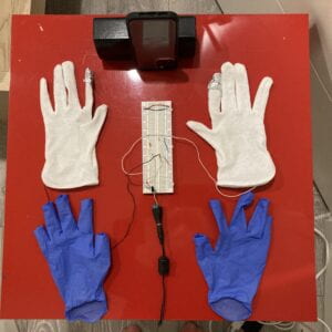
I cannot believe how much I learned about circuits in just two days. All my life I was intimidated by the amount of different parts that go on the breadboard, but alas, this week I started my journey into taming the beast. Over the last few days I created a short circuit, blew up an LED, and created a glove switch in tribute to the electric pop star, Michael Jackson. Here is a prototype of the Jackson Switch:
To create this switch, I used one of the circuit set-ups from the Labs with a 12V power source, a 5V voltage regulator, a 220 kOhms resistor and a white LED light. My father consulted me on my circuit and was my assistant in filming and doing the lighting for the video.
Below is the filming and circuit set-up:

Even when using latex gloves under the white gloves, my body still conducted electricity (albeit with low current and high resistance)! The LED would light up slightly when I put the gloves on, even though the ‘switch’ fingers weren’t touching. How would I prevent that?
Week 1 Lab Reflection
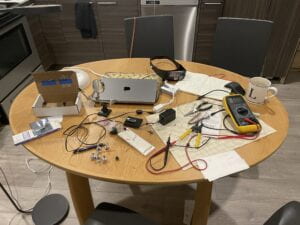
Using the breadboard turned out to be much harder than I thought. The good news is that it got easier with practice. First of all, the working table became a mess very quickly:

There are a few important things that I learned:
- using pliers to insert things into the breadboard would’ve saved me a lot of time.
- nails and physical computing do not go well together.
- making sure your wires are in the holes fully IS KEY. Most of the time if something didn’t work it was because of a connection problem.
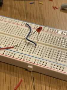
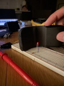
- I originally had a question as to why we have a resistor in front of an LED, but then it got answered when my red LED blew up (evidence below):

- Short circuits are real and will start smoking and burning the breadboard 🙂
- I need to invest in many tools (duct tape, scissors, pliers, etc.)
Questions (and failures):
- When I put two LED’s in parallel (or series) only the one red lit up even though the voltage was the same. Why?
- I was unsuccessful in measuring current (mutli-meter read 0.0 all the time)
- What do the numbers on the potentiometer mean?
- I did not fully understand two concepts: what is a voltage divider and why do we need a constant resistor to pair with a variable one?
And finally, my first working circuit:
