Lab 1: Tone Output
1 Connect sensor & speaker. In the process of checking the sensor input range and the speaker’s work, I do try the different values of delay and resistors with smaller Ohm. The sound interval is proportional to the ratio of delay to the duration, and the volume of the speaker also gets louder as the value of the resistor gets smaller. (review and summary for last week)
Using the map function to produce sound just makes me feel the joys of Dj.
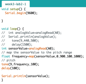
2 Play it loud. I add a transistor to play it loud. Something new happened when I hooked up to the FSR. The speaker emitted tone at random, and the value of analogRead did the same thing from 200, even when no one touched it. It seems that the transistor has an impact on the sensor, but I don’t think it should. Then I change the resistor from 10k Ohms to 220k Ohms, things went well. I guess it may be because the FSR was too sensitive, the resistor was turned up to make the variable resistor less sensitive. But I’m not sure. 🤔 Question~ (√) Transistor Amplifier:
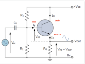
Afterward, I change the FSR to a potentiometer as input, which works.
3 Melody — “Castle in the sky”
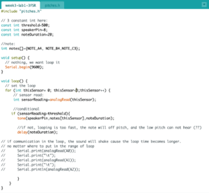
4 A musical instrument. In beginning, I just code it as diagrams on the labs, the speaker works but the pitches was so wired like off-pitch. A4 and B4 heard really similar, and C3 cannot be heard which makes me think it not works. Checking the sensor input told me everything about FSR is good. After that, I add the delay following the tune function, the pitches sound correct right now.
Is the reason for off-pitch the fast speed of the loop? 🤔 Question~ (√)
And after checking the pitches, I comment on the serial. print() in the loop since these make the sound to be quivering. Now the pitches sound relatively correct and smooth.
sound without delay()
sound with serial. print()
sound that relatively smooth
Lab 2: Servo motor control
Questions🤔 :
- After connecting the power supply, there is no immediate response, and needs to wait for a while.
- I use the millis() to set the interval of time, and try the numbers from 20ms to 1000ms, the shorter the interval time, the more frequent the jitter. How to find a reasonable number? (√ ) It is better to code like this: millis()-lastMoveTime>1000
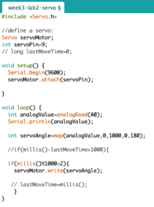
millis()&1000<2;
The servo motor will move when the code is first uploaded and no one touches it. (√ ) Give a fived value at the beginning to control the angle of the motor.
millis()&20<2;
-
The 46uF capacitor I used was later changed to 2.2uF. The servo motor was slow to respond, but it returned to normal after a while. Does the capacitor function in this circuit to smooth voltage and current? How to determine how large a capacitor is to use? (√ ) 2.2µf is too small for most motors. Capacitors do have some effects on the whole circuit just at the transistor’s problem. At least 10uf to 100uf.
- Input through FRS, if LED is output. When the FRS is not touched, the analogRead values start from about 0-3. But connected to the servo, its starting value changes to around 100, which seems very sensitive. Why? (√ ) It always has some changes, that’s the reason we need to find each sensor’s range.
Lab 3: Have a try~
Ideas: I try to construct a relationship between the potentiometer, LED, photocell and speaker. The potentiometer controls the lightness of the LED, and the photocell detects the lightness of the LED to give the signal to the speaker to play. I wish that when the lightness value is not matched to the threshold, the melody will stop.
Problem: The first picture is my original code, through this version of code, the speaker does play when the photocell detects the threshold value, but it only paly once. And the potentiometer can no longer control the LED after the player starts playing music (that is after the analog value reaches the threshold). I guess there must have been problems in my code, but I have no idea how to adjust it.
1 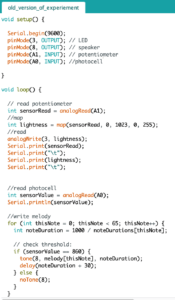 2
2 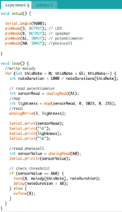
Solution:After I ask for Tom, I realized I have not built a correct understanding of the loop. If I want to reach my original idea, the analogRead value of the potentiometer and photocell should be included in the loop. All the relevant initializations should be inside the loop, but I separated the read and write in my code. The second picture is the modified version of the code. It works as expected but the tone of the melody is strange because the loop function does have effects on the tone, it’s not a good way to play a melody.
Lab NOTE:
- analogWrite() —- change the on-off ratio of the output (also known as the duty cycle).
- tone() —- change the frequency.
- Vibrations get fast enough, above about 20 times a second. So 20 times a second is 20Hz. For 20HZ, the period is 1/20 second or 0.05 seconds. Frequncy=1/period
- All digital pins can be connected to Servo pins, not just PWM pins.