Category Archives: PCOMP

Week 7 – Midterm Project Documentation(2)

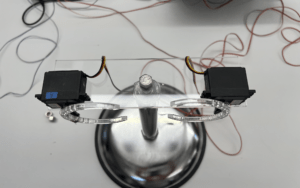
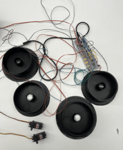
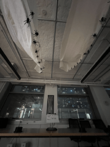
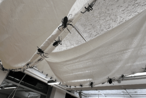
After we finish the code part last week, we are focusing on the fabrication this week. Anna took lots of energy on the 3D printing button since we wanted it similar to the arcade button. And she also made an excellent base for fixing the two servos and found the best solution for the falling web.  The fabrication details could be found in  Anna’s Blog.

w7p2 w7p3

Anna makes the pretty stand for the servos.

w7p1 The 3D printing buttons (base) and lots of soldering work.

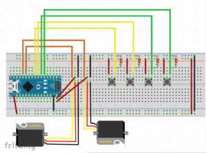
And the schematic diagram.

w7p8

I continue to work on the p5js to give a better visualization for the game, using Illustrator to draw the Halloween theme background. And add some sound to give the start and end for the game, making it to be more organizable. 

w7p4

And then we step into the User Testing stage.  We invited several ITP mates to join the game and luckily most stuff is going well. But we still have some parts that should be adjusted.

  1. we need to take care of the long wires and organize it.
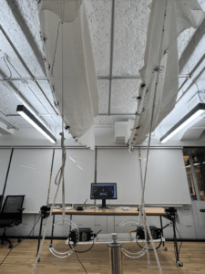
  2. And the distance of the racing area should be adjusted since the web should cover the people when it fell down.
  3. The button needs to be fixed because some participants will hit it hard, so the button will be pushed farther, and the distance will be longer, which will be unfair. On the other hand, it’s a tricky spot for a game, and it’s fun if not to fix it. But anyway, we don’t want to complicate the racing game.
  4. And we also find the best way to connect the rope of the web and servo, we need to find the right Angle. It should be can either pull on the rope when the servo is still or quickly release it when the servo starts rotating.

The testing process is quite interesting and testees said the game makes space to be the ITP’s sports room. 😂

1st Testing Group. Running back and forth 😄, for some technical reason, the first round hasn’t triggered the web to fall.


2ed Testing Group. It’s hard to play the game without screaming!


3rd Testing Group. It’s really a sports game, so tried cause it’s the third time for us to test it.


The first and also the last Testing Group, after we set it all up for the class show. Everything goes really well, and the web looks much better after we stick the spider!    (Oh, I have to hate the spider, it took me 1 hour to bend it and stick it 😭)

w7p7 w7p5w7p6

The show in class:


Week 6 – Midterm Project Documentation(1)

My partner Anna and I wanted to make a game and it was Halloween-themed. We took inspiration from the pie face challenge and decided to make a racing game.

Pie Face Challenge

Regarding the format of the game, we wanted the game to have an interface just like an arcade and also for the player to interact with the physical space during the game.
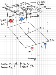
w6p1 sketch

So we plan to have FOUR buttons available to TWO players. One player will only have the move-up and left buttons and the other player will only have the move-up and right buttons.

The two buttons would be distributed at opposite ends of a distance, and both players would bounce back and forth to press the button to move their character quickly across the interface to the end within the distance. Each button can only be pressed once at a time, and that’s the rule. So it’s all about the speed of the two players.

The winner who reaches the finish line first will trigger a spider web to fall over the other player’s head, as a punishment for the loser.

For this idea, we faced TWO Difficulties. The first was the serial communication between the Arduino and the p5js, and the second was about the design of the spider web, as it needed to be light enough and big enough.

For the fabrication: Tom recommended we find inspiration from a pit trap. We discovered the Drop Net Kit System video on the internet thanks to Tom’s suggestion, and we believed we could apply this approach to construct a spider web.

Drop Net Kit System

And we found a sheet of fabric on floor, and after several test we choose to use magnetic to attach the web to ceiling pipe. And Anna use 3D printer made big button, the button base is nice but the lid is not very satisfactory, we need take more attempts on it.


For the code: We couldn’t figure out how to build one press for one step at first since the Arduino readout is continuous and the control object on the p5js continues to go along with each reading. Therefore I adjusted the game’s rules 😂 so that the player not only needs to reach the destination quickly but also avoids obstacles. I established a time threshold for entering an obstacle, and if the player does not avoid it in time, the game ends when the time to touch the obstacle exceeds the threshold. The game might then result in two losers and no winner, or with one winner and one loser. However, although modifying the game’s rules solved the input problem, we still had issues with the output. The first version of the game was suspended. 

It was then that, thanks to Yonata’s assistance with our code, he provided me insights on how to construct one press for one step, allowing me to fix the initial problem and return the game rules to their original state. As a result, in the second version, the majority of the logic is coded in Arduino, which is simpler to operate and understand than the previous version, in which the majority of the logic was coded in p5js, and even the output problem was fixed.

However, there are always twists and turns!😮‍💨 The page lag becomes so severe after completing the serial input and output that the game cannot be played at all. The game progresses smoothly if one player’s output is commented (I tried here initially by lighting the led instead of the departure motor) and just one output is retained.


The great news is that after attending Tom’s office hours, both versions’ problem was resolved; thank you again, Tom, for your assistance! 👏👏

The difficulty with not being able to get the Arduino to receive the p5 instructions in the first version was due to the misinterpretation of the code.

First, controlling the flow of asynchronous serial communication via handshaking does not necessitate control of all communications; rather, it could be managed independently for the specific logic settings. In my code, for example, when the LED must be turned on only under particular conditions, serial. available()>0 can use to confine only this part of the whole logic. Second, when I manually enter a value as transmission data, I don’t have to convert the byte to ASCII. Giving the value manually different from inputting the data with the keyboard.

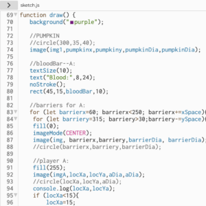
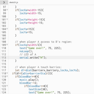
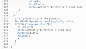
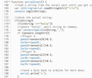
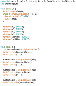
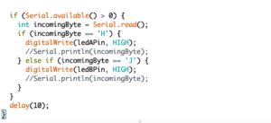
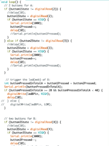
Most of the logic of this version was coded in p5js. (for testing, just one player’s part)
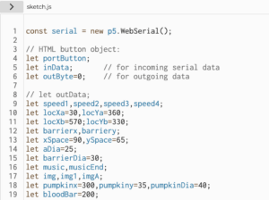
w6p2

w6p6

w6p3

w6p4

w6p5.    p5js code

w6p7

w6p8.  Arduino code


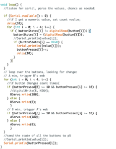
The problem with the second version is still a coding issue. Tom suggests suggested I add some delay after each if statement, as the extremely laggy response, may be caused by the numerous loops. But it didn’t work. Then Tom gave me another train of thought, reorganizing the code with Array to decrease the number of repeating loops. And it works! The code is much cleaner too! The page no longer becomes stuck!

Most of the logic of this version was coded in Arduino. 
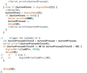
w6p9                        Modified Code

w6p11BEFORE          w6p10AFTER


So we have two versions of the game. After discussing with Anna, we decided to use the second version since the game was simpler and more straightforward, allowing players to focus on speed. The first version demanded that the player not only be swift but also avoid obstacles, so the game became more difficult. 
 

Week5 – Lab – Transistor & DC Motor & Stepper Motor

Lab 1 Transistor:

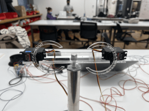
The blink Sketch has not been achieved on the DC Motor. A guess here is that the Arduino hasn’t been designed to provide enough power to make the motor turn. Even though I have an external power supply, the blink sketch for the DC motor still needs a motor driver.

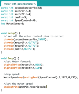
 The LED has achieved. And I can’t change the speed of the motor according to the lab’s code, after I change the transistor pin from digital to analog, the potentiometer can control the speed of the dc motor. When the dc motor connects to the 12-volt DC wall adapter, the rotation speed increases. 


                                With 3.3V                                                                      With 12V

Lab 2 DC motors H-Bridge:


— Application with H-Bridge:

I want to use the potentiometer to control the speed of the DC motor. And I discovered that using the motor driver, I can vary the speed of the motor between 0 and the maximum, which means I can stop the rotation of the motor rather than just slowing it down. And I stick several colorful paperboards to it, it seems like a little fan.

w5p1   

Lab 3: Step Motor H-Bridge:

One Step At A Time:


Revolution:

It didn’t succeed. I still haven’t figured out the reason. I tried to swipe the two pins to each coil and swipe the wire of one coil to another, but it didn’t work. 


Week3 – Labs – Tone output & servo control

Lab 1: Tone Output

1 Connect sensor & speaker. In the process of checking the sensor input range and the speaker’s work, I do try the different values of delay and resistors with smaller Ohm. The sound interval is proportional to the ratio of delay to the duration, and the volume of the speaker also gets louder as the value of the resistor gets smaller. (review and summary for last week)

Using the map function to produce sound just makes me feel the joys of Dj.

w3p1

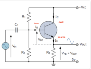
2 Play it loud. I add a transistor to play it loud. Something new happened when I hooked up to the FSR. The speaker emitted tone at random, and the value of analogRead did the same thing from 200, even when no one touched it. It seems that the transistor has an impact on the sensor, but I don’t think it should. Then I change the resistor from 10k Ohms to 220k Ohms, things went well. I guess it may be because the FSR was too sensitive, the resistor was turned up to make the variable resistor less sensitive. But I’m not sure.  🤔 Question~ (√)                             Transistor Amplifier:   

     w3p7

Afterward, I change the FSR to a potentiometer as input, which works. 


3 Melody — “Castle in the sky”


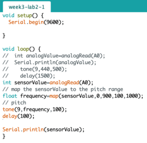
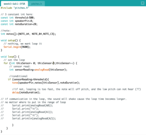
4 A musical instrument. In beginning, I just code it as diagrams on the labs, the speaker works but the pitches was so wired like off-pitch. A4 and B4 heard really similar, and C3 cannot be heard which makes me think it not works. Checking the sensor input told me everything about FSR is good. After that, I add the delay following the tune function, the pitches sound correct right now.

Is the reason for off-pitch the fast speed of the loop? 🤔 Question~  (√)

And after checking the pitches, I comment on the serial. print() in the loop since these make the sound to be quivering. Now the pitches sound relatively correct and smooth.

sound without delay()

sound with serial. print()

sound that relatively smooth


w3p2

Lab 2: Servo motor control

Questions🤔 :

  •  After connecting the power supply, there is no immediate response, and needs to wait for a while.
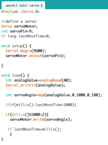
  • I use the millis() to set the interval of time, and try the numbers from 20ms to 1000ms, the shorter the interval time, the more frequent the jitter. How to find a reasonable number? (√ ) It is better to code like this: millis()-lastMoveTime>1000w3p4

millis()&1000<2;

The servo motor will move when the code is first uploaded and no one touches it. (√ ) Give a fived value at the beginning to control the angle of the motor.

millis()&20<2;

  • The 46uF capacitor I used was later changed to 2.2uF. The servo motor was slow to respond, but it returned to normal after a while. Does the capacitor function in this circuit to smooth voltage and current? How to determine how large a capacitor is to use? (√ ) 2.2µf is too small for most motors. Capacitors do have some effects on the whole circuit just at the transistor’s problem. At least 10uf to 100uf.

  • Input through FRS, if LED is output. When the FRS is not touched, the analogRead values start from about 0-3. But connected to the servo, its starting value changes to around 100, which seems very sensitive. Why? (√ ) It always has some changes, that’s the reason we need to find each sensor’s range.

Lab 3: Have a try~

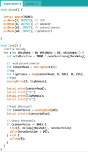
Ideas: I try to construct a relationship between the potentiometer, LED, photocell and speaker. The potentiometer controls the lightness of the LED, and the photocell detects the lightness of the LED to give the signal to the speaker to play. I wish that when the lightness value is not matched to the threshold, the melody will stop.

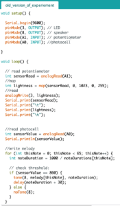
Problem: The first picture is my original code, through this version of code, the speaker does play when the photocell detects the threshold value, but it only paly once. And the potentiometer can no longer control the LED after the player starts playing music (that is after the analog value reaches the threshold). I guess there must have been problems in my code, but I have no idea how to adjust it.

              1 w3p5                            2  w3p6 

SolutionAfter I ask for Tom, I realized I have not built a correct understanding of the loop. If I want to reach my original idea, the analogRead value of the potentiometer and photocell should be included in the loop. All the relevant initializations should be inside the loop, but I separated the read and write in my code. The second picture is the modified version of the code. It works as expected but the tone of the melody is strange because the loop function does have effects on the tone, it’s not a good way to play a melody.


Lab NOTE: 

  • analogWrite() —- change the on-off ratio of the output (also known as the duty cycle).
  • tone() —- change the frequency.
  • Vibrations get fast enough, above about 20 times a second. So 20 times a second is 20Hz. For 20HZ, the period is 1/20 second or 0.05 seconds.  Frequncy=1/period
  • All digital pins can be connected to Servo pins, not just PWM pins.

Week2 – Labs Document – Input & Output

Lab: Digital Input and Output

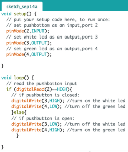
1 Everything goes pretty well when I try to set the pushbutton to control 2 LEDs through programming. The physical output does consistent with my expectations. And I also measure the changes in voltage across the pushbutton. 


w2p1

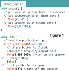
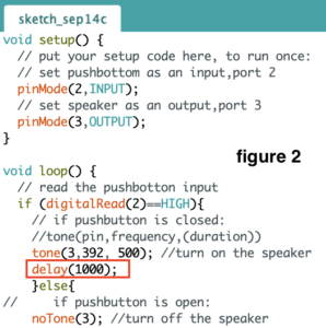
2 But after I tried to replace the LED with a speaker and write the code as figure 1, the speaker was not working. If I add the delay() after the tone(), as figure 2, it works. I still haven’t figured out the reason. (Q)

w2p3 w2p2

Lab: Analog In with an Arduino

1 Lab that follows the video of “Analog Input”

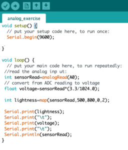
w2p5   w2p4

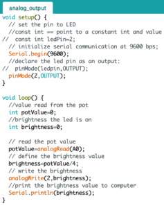
2 Lab of “Analog Output”

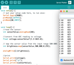
w2p6

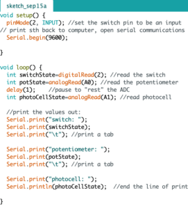
Code Note: 1 analogRead(10 bits) — INPUT; analogWrite(8 bits) — OUTPUT; 2 const int: the pointer can point to a constant int and the value of the int pointed by this pointer cannot be changed. 3

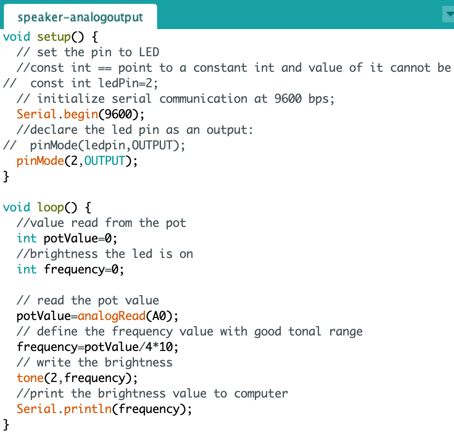
3 Replacing the LED with a speaker. (Remember give a good enough tonal range!)

w2p16

4  Wiring a photocell to measure light

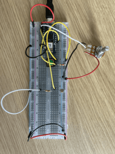
w2p8

5 find your sensor range

1 photocell & 1 LED

w2p9

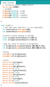
6 1 photocell &1 FSR & 2 LEDs

w2p10

1 photocell & 1LED & 1FSR & 1Speaker

Code Note: For sensor to control digital input: analogWrite(pinMode, variables (brightness, pitch))

Lab: Sensor change detection

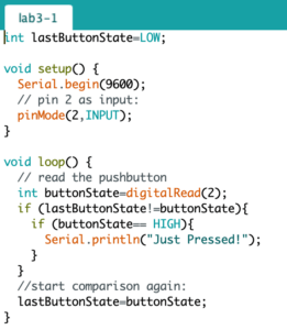
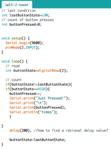
1 Read the pushbutton statement change

w2p11

2 Count button presses

 w2p12

I found that the pressing condition would be recorded continuously by the serial monitor, so I give a delay after the comparison. But the value of delay was tested by several times, does the value come from experience?  And can the delay be replaced by millis? I guess. (Q)

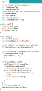
3 Long press & Short press

w2p13

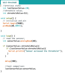
4 Threshold Detection

w2p14

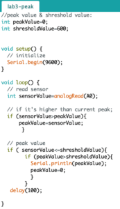
5 Detecting a Peak Value

w2p15