The Reverse Vending Machine
My Name: Kitty Chen
Instructor: Professor Inmi Lee
- CONCEPTION & DESIGN
In the reading The Design of Everyday Things, Don Norman stated that “the information in the feedback loop of evaluation confirms or disconfirms the expectations, resulting in satisfaction or relief, disappointment or frustration.” In this project, we want to explore more about the concept of interaction, and try to figure out how feedback which disconfirms the users’ expectations might impact the interaction process, and whether users will rely on their own exploration or the given instructions.
Before making our project, we did some research on intuitive design, counter-intuitive design and useless conceptual designs. Intuitive Design by Interaction Design Foundation reminded us that users will feel that a design is intuitive when it is based on principles from other domains that are well known to them. Counter-intuitive Ideas in Design by Aksu Ayberk inspired us that to chase counter-intuitive ideas, designers have to demolish the old way of doing things. Katerina Kamprani’s useless conceptual designs prove that designs do not have to be usable in a daily basis, but can also expresses concepts and attitudes.
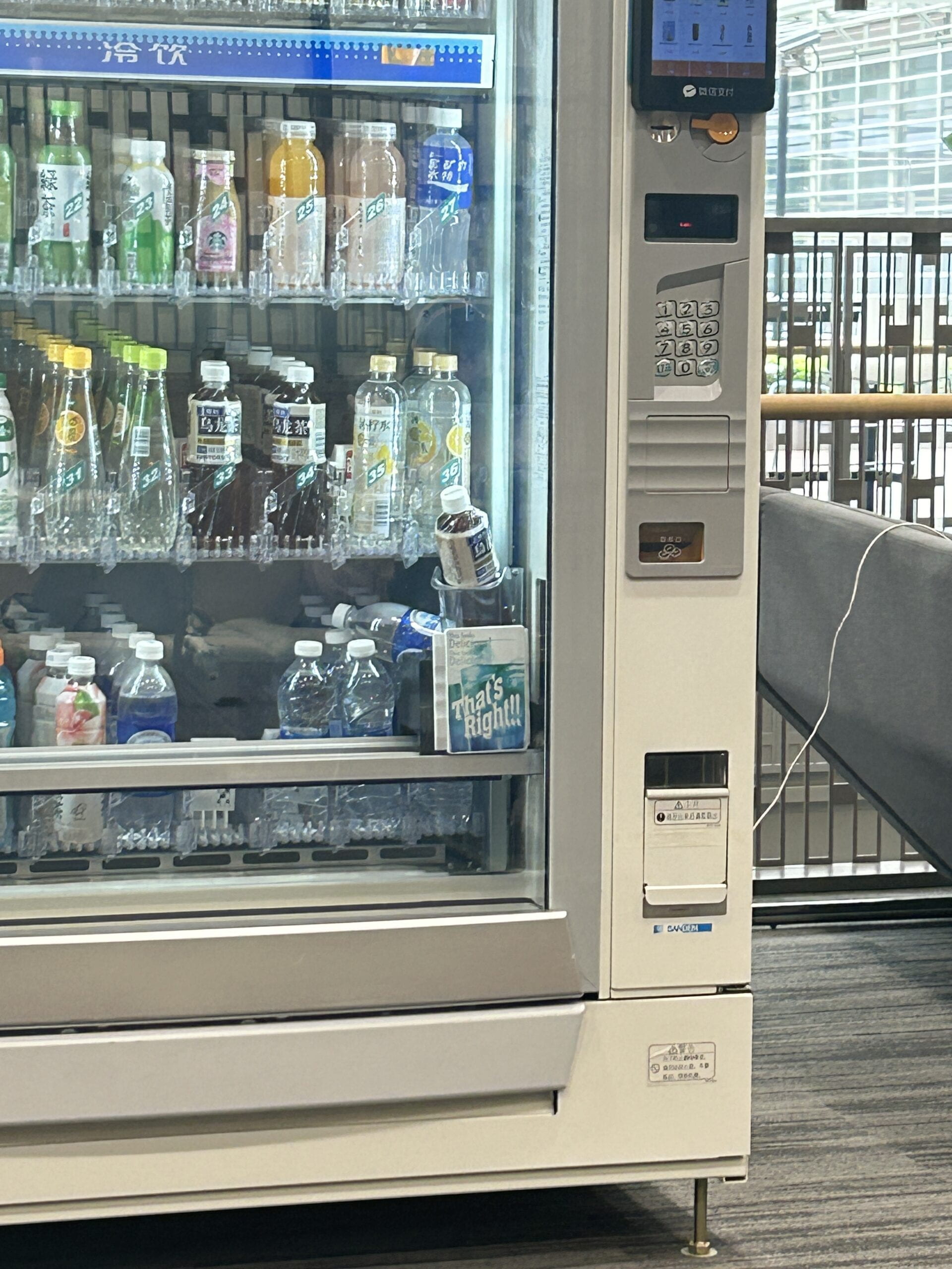
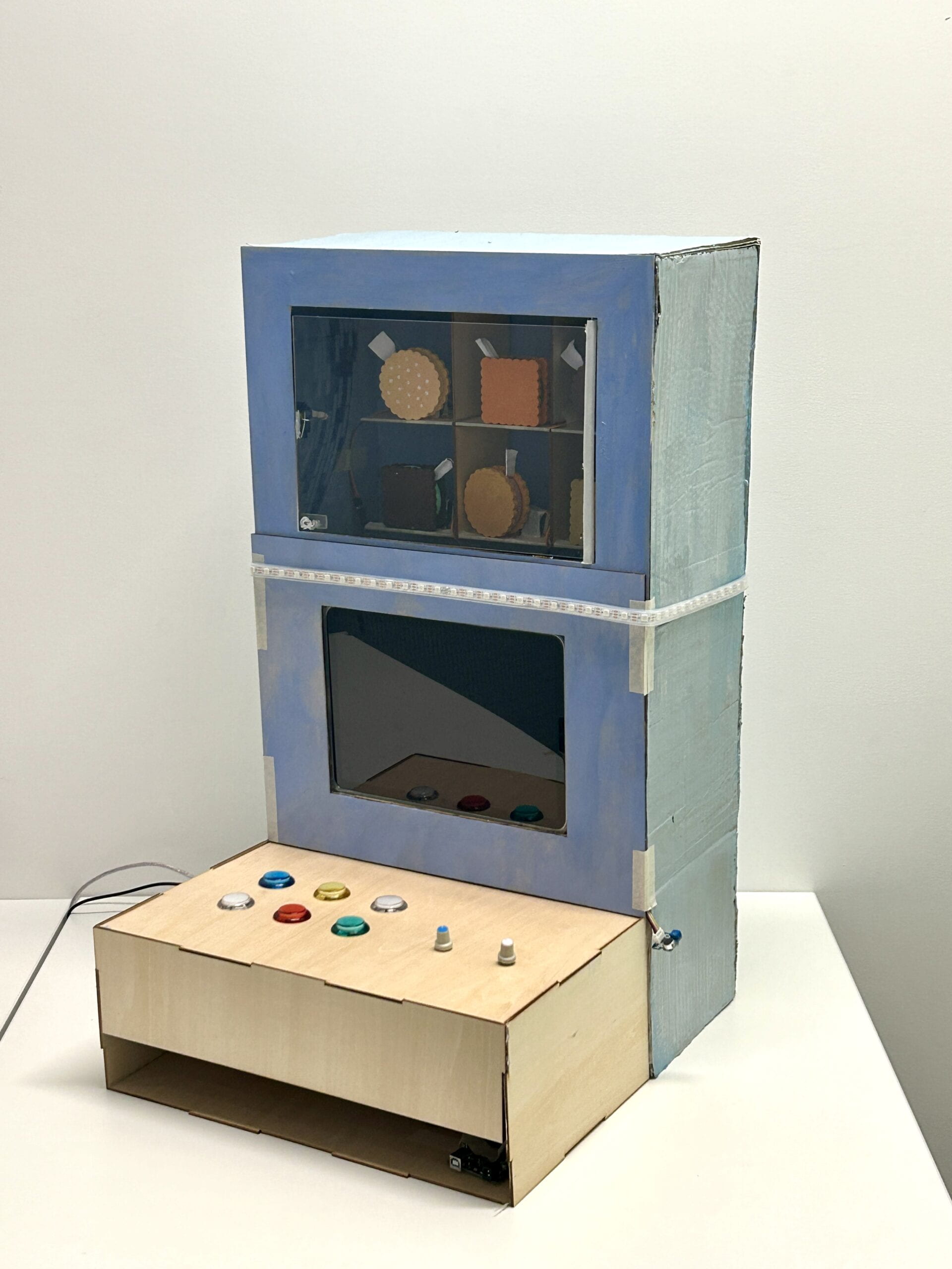
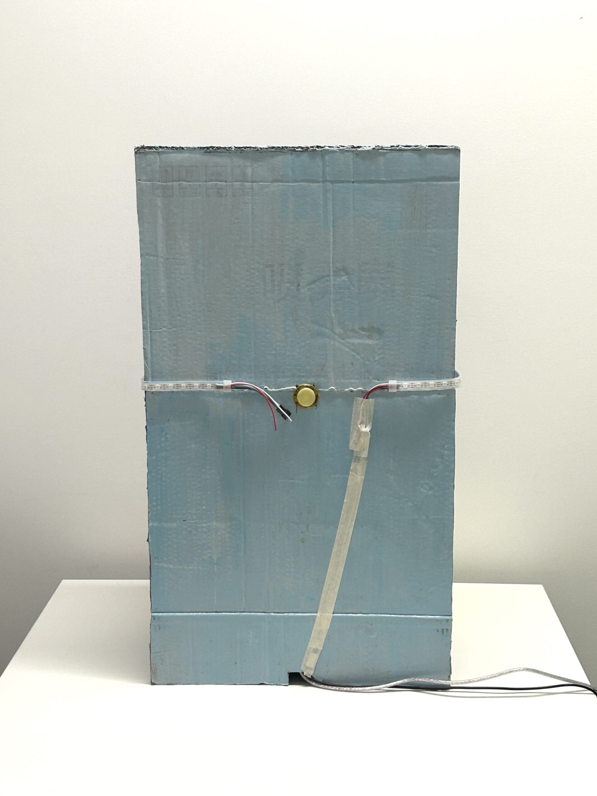
Our inspiration came from the vending machines in the campus, which always functioned abnormally. We designed a reverse vending machine selling fortune cookies. Unlike a usual vending machine, when the user chose the fortune cookie they wanted, all the cookies would be pushed down by servos, except the one they want. Then, some games would appear to help the users get the cookie they wanted. On the screen, there will be a puzzle game, in which users could use two potentiometers to control the puzzle; after that there will be a screaming game, in which a balloon will appeared and its size was according to volume. After the user reached a certain volume, the screen would show two arrows pointing left and right, and the LED light strip attached on the vending machine will light up one by one iteratively, encouraging people to go to the back side and check. On the back side, there was a button which controlled the glass window of the vending machine. Once the button was pushed, the window would open and users could grab the cookie and get their fortune. Importantly, the back button could potentially be pressed at any stage of the interaction process; and once it is pressed, the glass window will open to let the user get the item they want. We designed some hints to show this, like the emphasized word “back” during the instructions. As part of the design, we wanted to find out if users could figure out that pressing the back button can help skip the previous tedious games, no matter by exploring the project or interacting with it for multiple times.
The whole counter-intuitive project was more like an experiment. As designers, we observed users’ behavior when they faced feedback that was not aligned with their expectations (e.g. the falling cookies) and how they explore our project, in order to reflect the concept of “interaction”. This project was not focusing on users’ own experience, but our experimental observations on users’ interaction behaviors. The goal was never about intending to make users happy or confused, but conveying a reflection on the interaction process.
In the user testing session, we received some suggestions and made some changes on the technical parts and the appearance. Initially, the puzzle showed up when the users were choosing the cookies they want, which was not in order. Thus, we used Processing to control two Arduino to make sure that only when the choosing part finished can the puzzle part started. Also, the users thought that we could improve its appearance, so we changed the cardboard shelves into wooden ones, organized the wires and painted the cookie detailedly. I think the adaptations were effective, because they gave the project a nicer look and a clearer instruction. There were also some comments that our project was not clear enough and made the users confused. However, we insisted not to make too many directional instructions because this was not aligned with our goal – again, we wanted to observe what the user would choose to do in this situation, but not giving them a clear instruction and telling them what to do next.
- FABRICATION & PRODUCTION
The production process can generally be divided into four parts – the appearance, the fortune cookies, the puzzle game and the shouting game, and the glass window.
1) Appearance
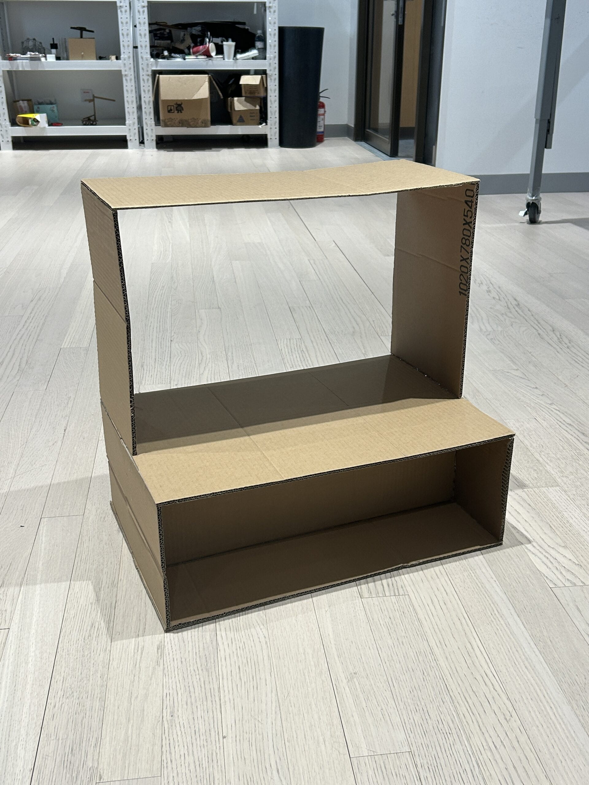
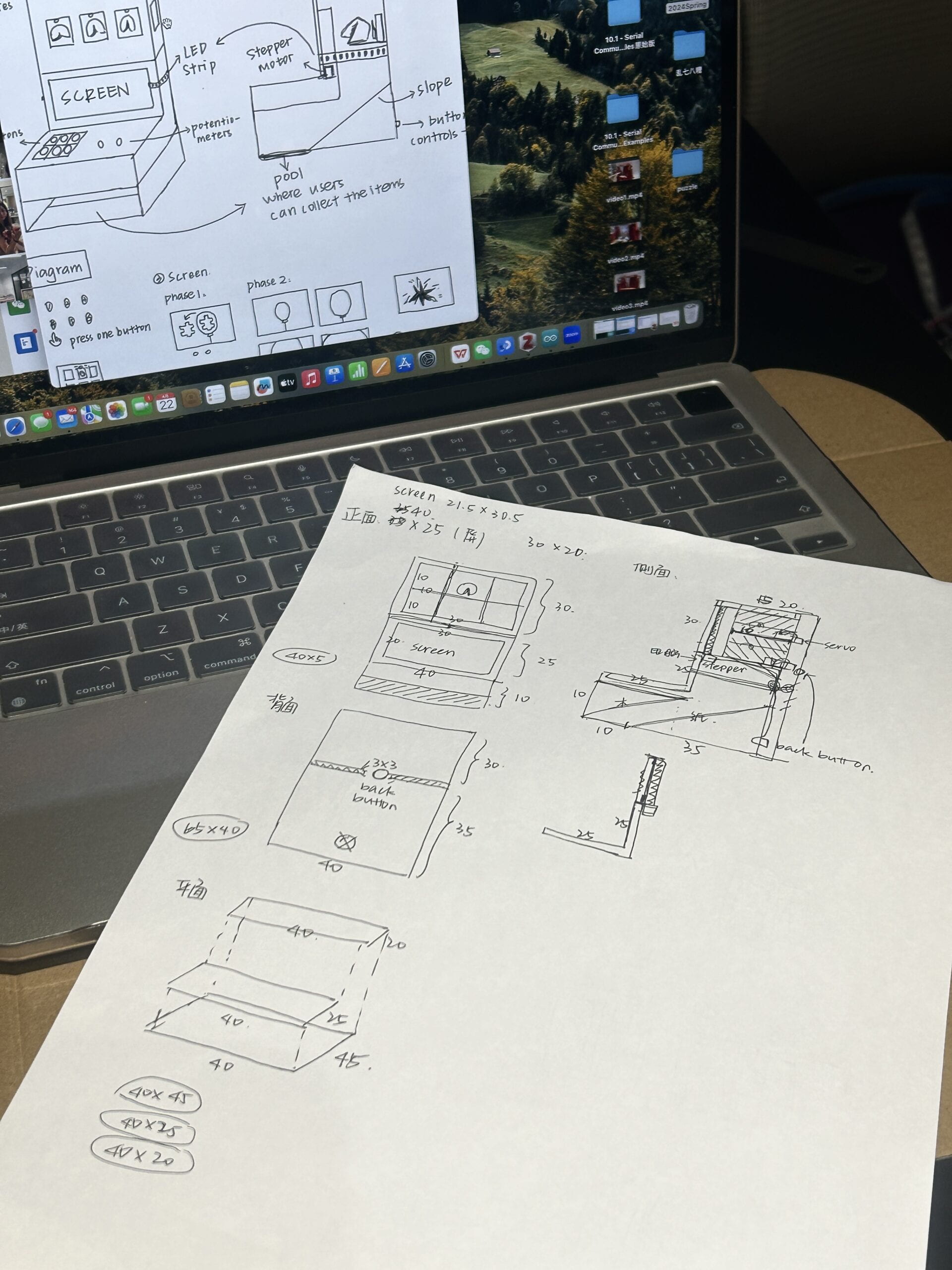
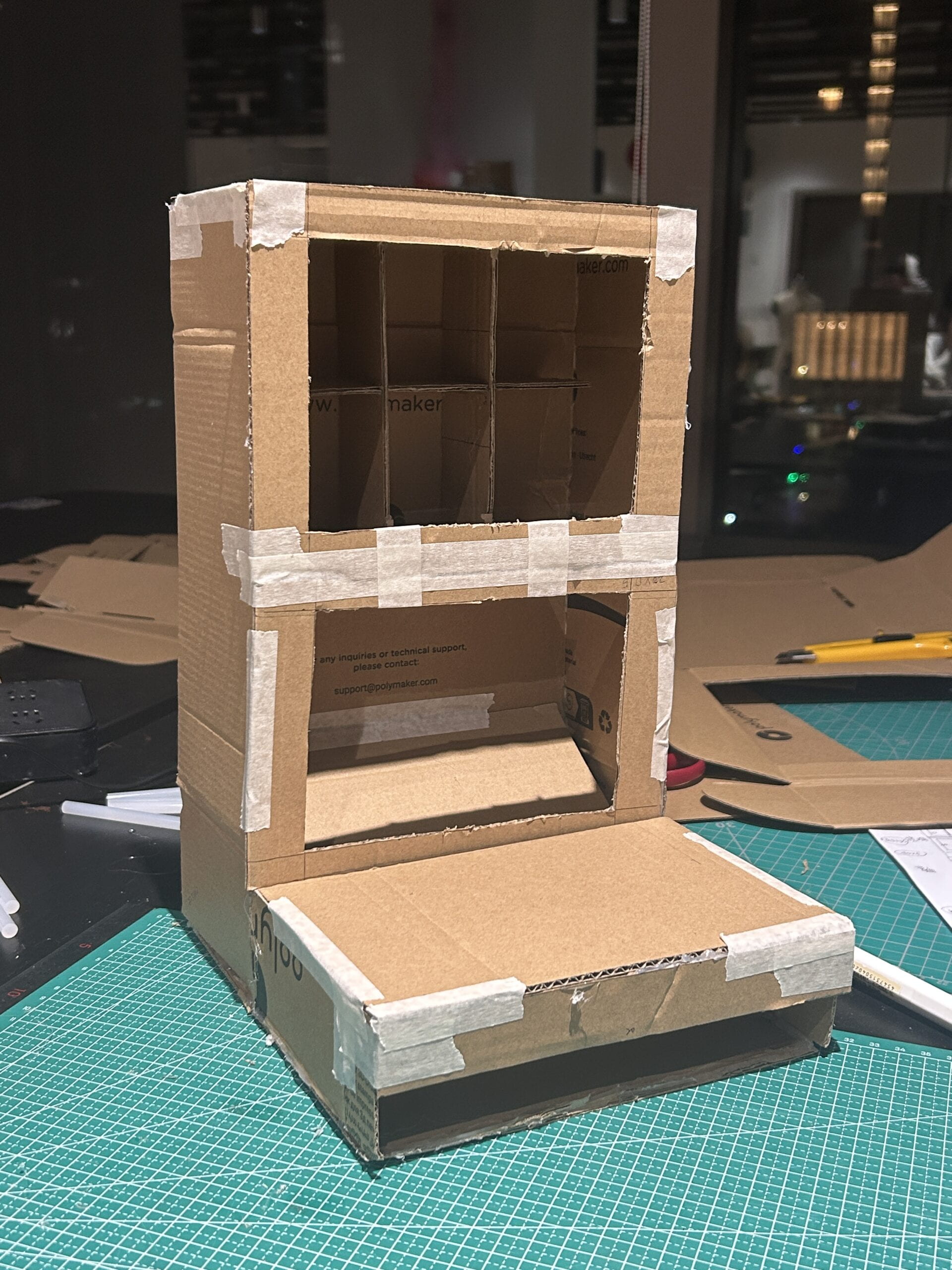
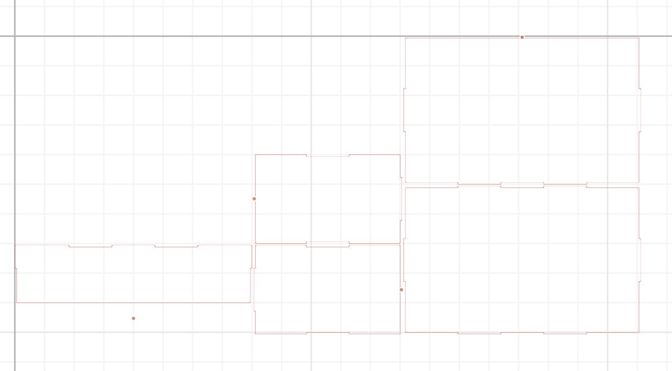
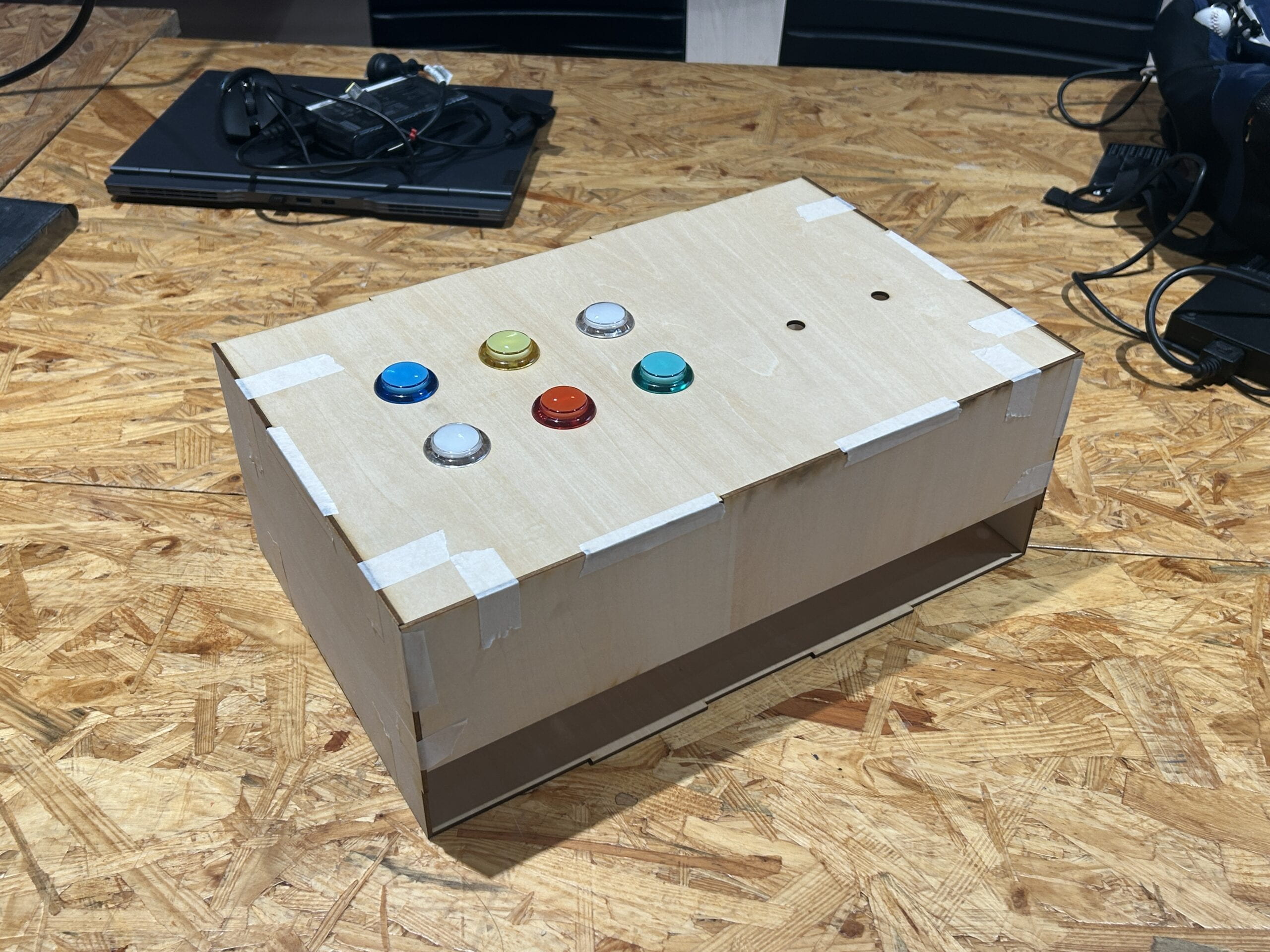
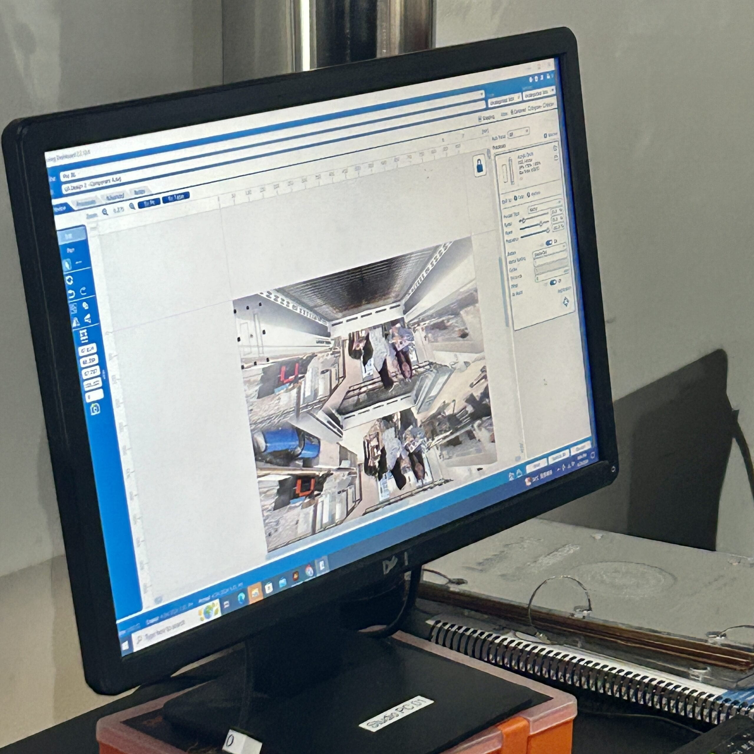
We first drew a sketch to clarify our thoughts. We first made a prototype out of cardboard to see if it could work. We planned to laser cut wooden board to build the whole appearance, however, the vending machine is too big for the wooden board. Therefore, we decided to use wooden board for the front part, and use cardboard for the bigger back part.
2) Fortune Cookies (Arduino1)
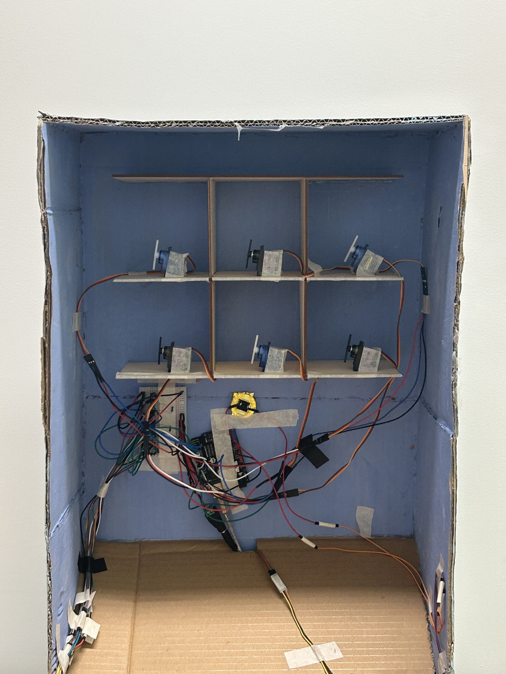
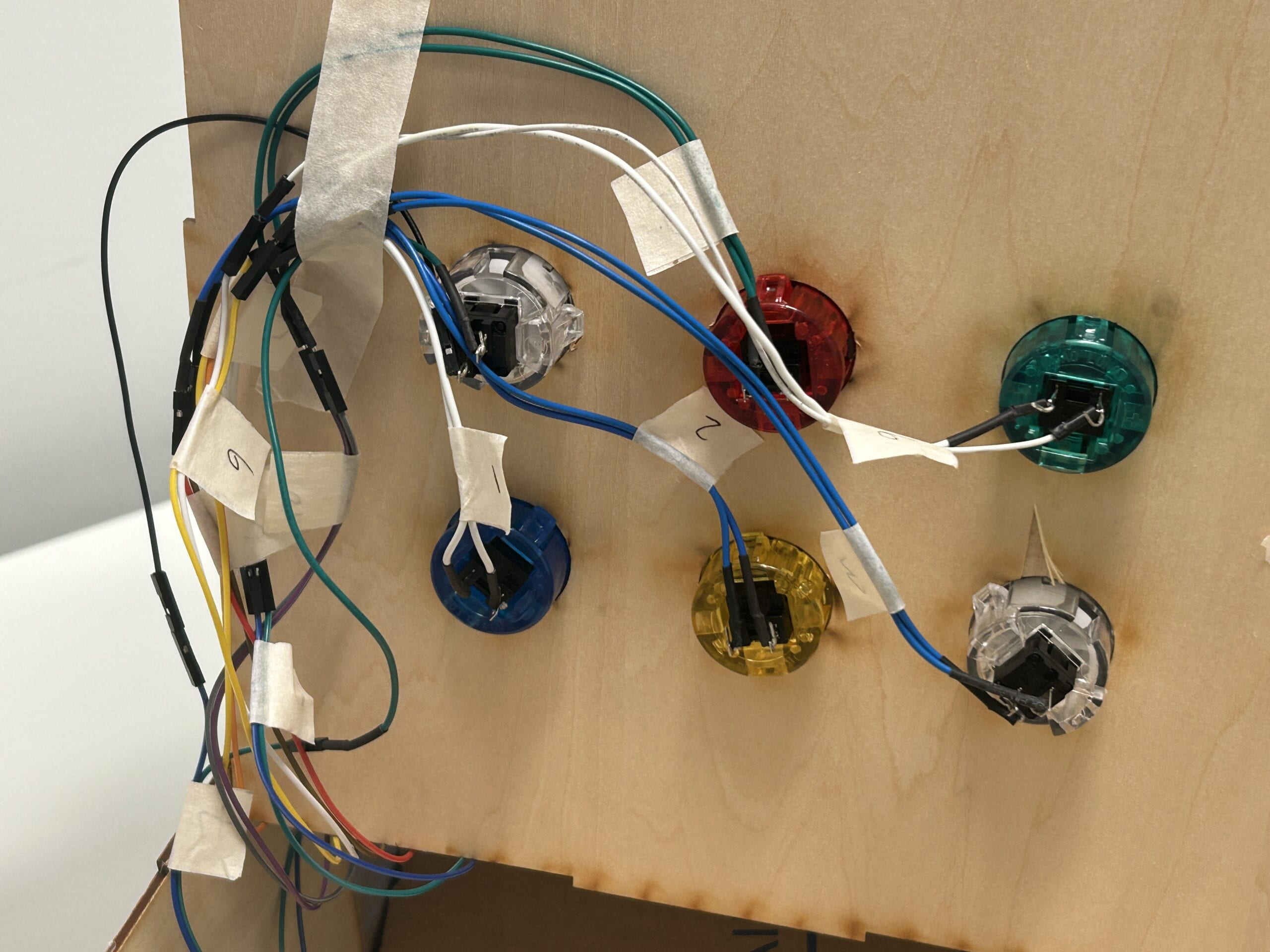
In this part, the user would choose a cookie, and all the cookies would fall down, except for the one they chose. In order to achieve this effect, we used six buttons (for the users to choose) and six servos (to push the cookies down), marked them with numbers, and connected them to the same Arduino. As for the coding, we initially used several “if” statements to make the other five servos turn 150 degrees when one button was pressed. However, this caused the servo to rotate only when the button was pressed, it would return to its original position after the button was released, so the servo could not push the cookie down. To address this problem, we then tried to used “while” statement inside of “if” statement, which means that if the button was pressed, only when the button was released could the servo start to rotate.
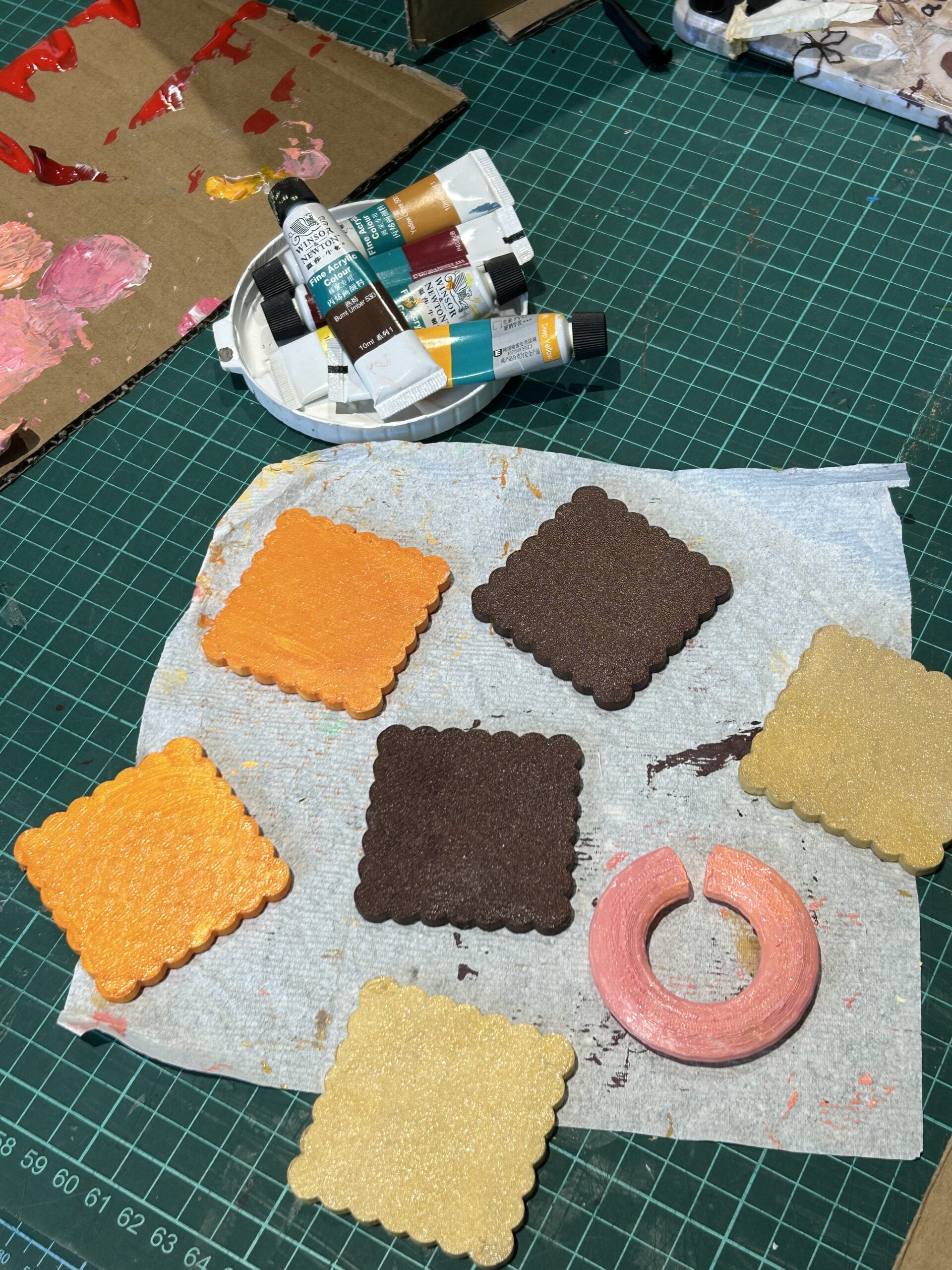
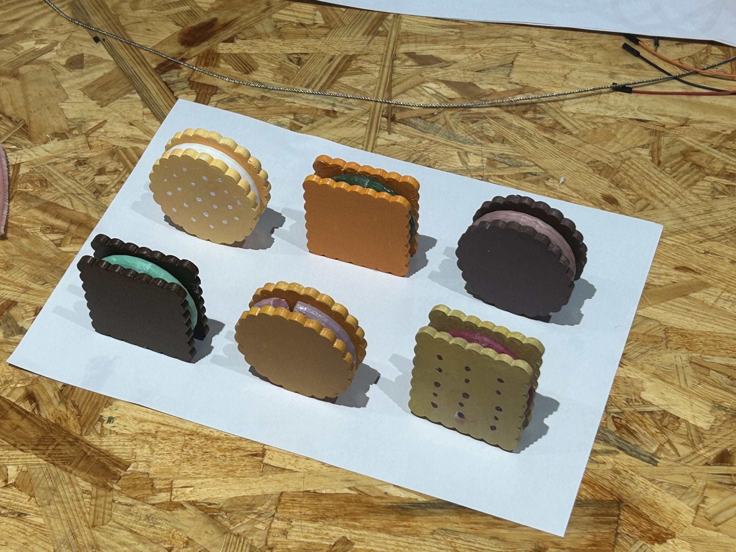
The fortune cookies were 3D printed. The fillings inside were made by a torus minus a cone, so that we had spaces to stuff fortune notes. The cookies outside were consisted of a large circle/square and multiple small circles. We then painted them into different colors.
3) Puzzle Game and Shouting Game (Arduino2, Arduino3)
The puzzle game appeared only after the cookies fell down. To achieve this order, we added an “if” statement in Arduino to make the serial port print “1” if a button was pressed. Then after receiving the “1”, Processing would run stage1, which was the puzzle game. In the puzzle game, we drew the pictures of the puzzle and connected two potentiometers. We soldered the potentiometers and the wires so that the analog read could be more stable. Then, we used the “map” function to translate the potentiometer analog read to the height and width in the frame to control the puzzle. After the puzzle was put in the right place, we wrote a “playMelody()” loop so that the buzzer can play a small piece of celebrating music.
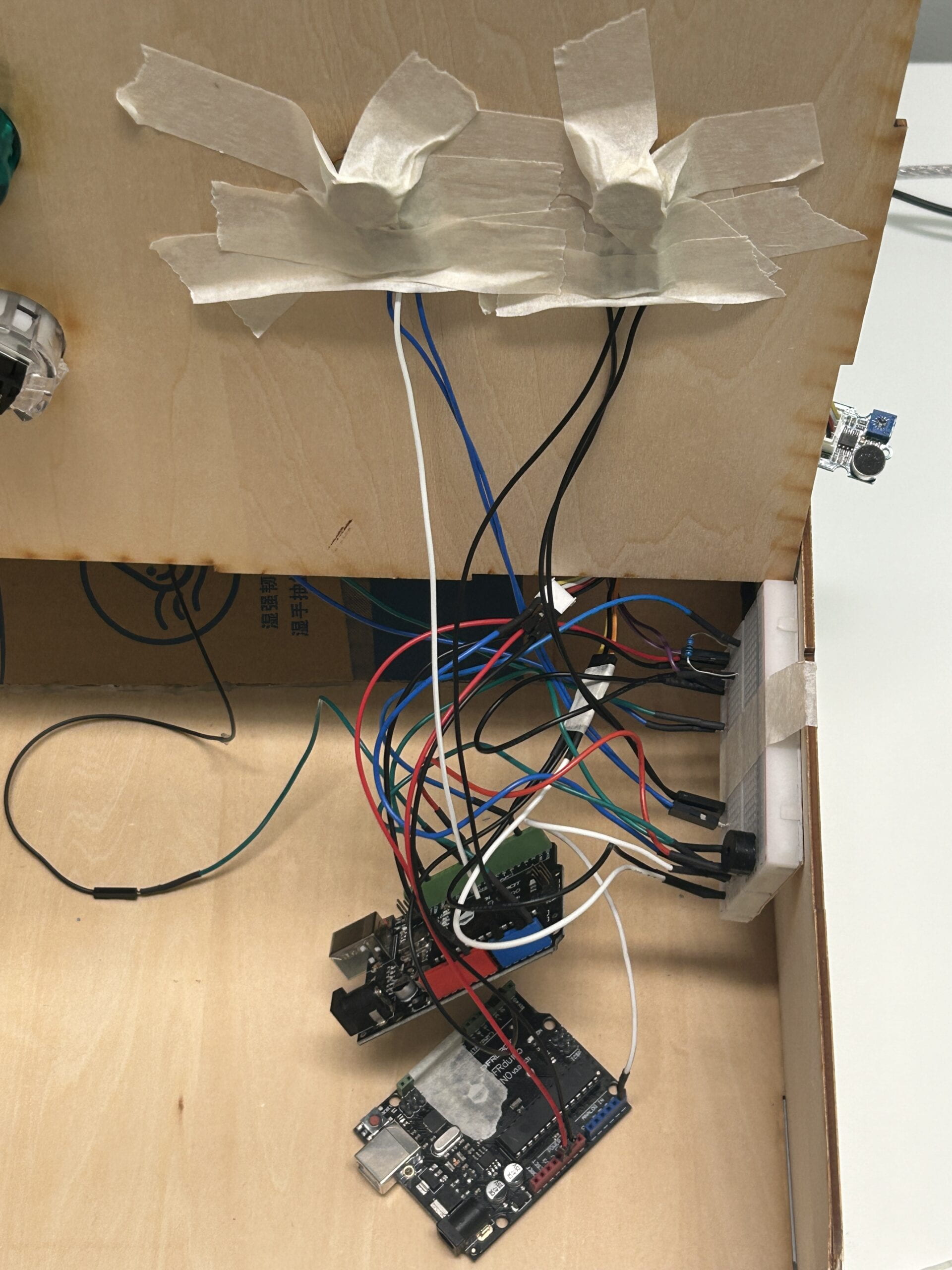
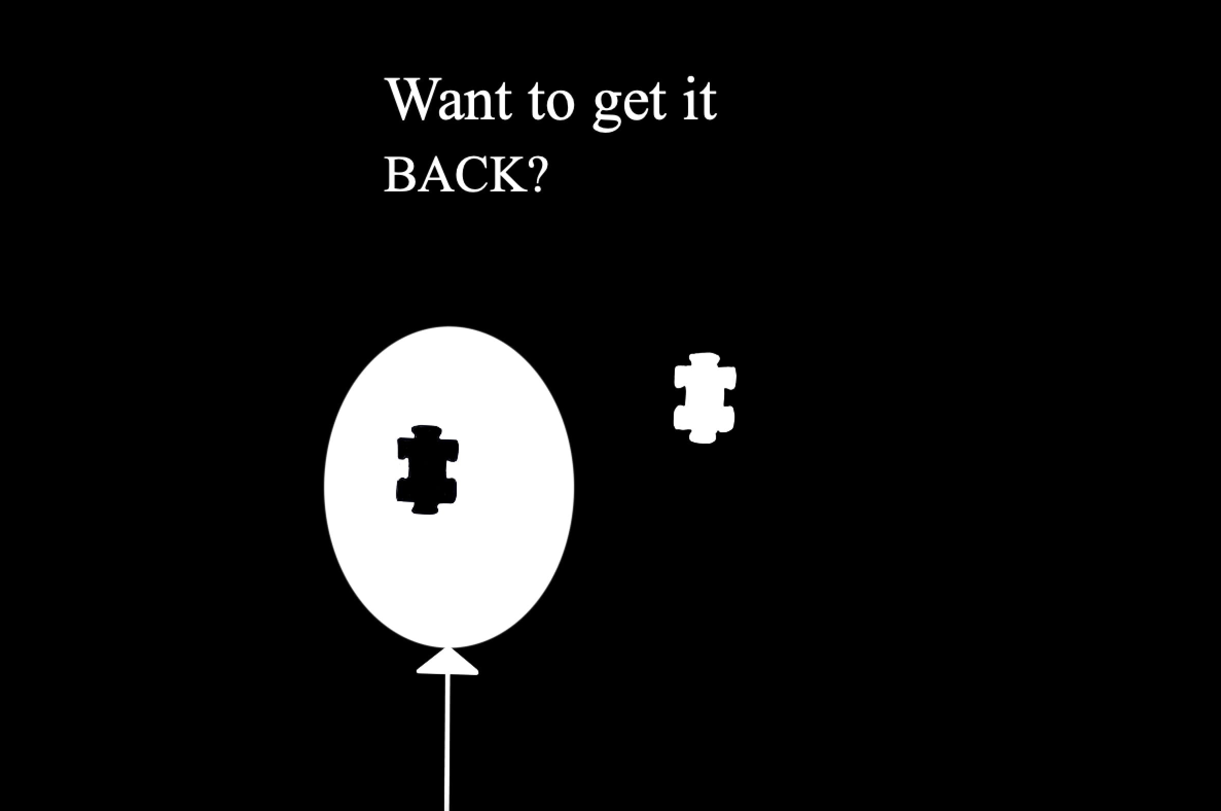
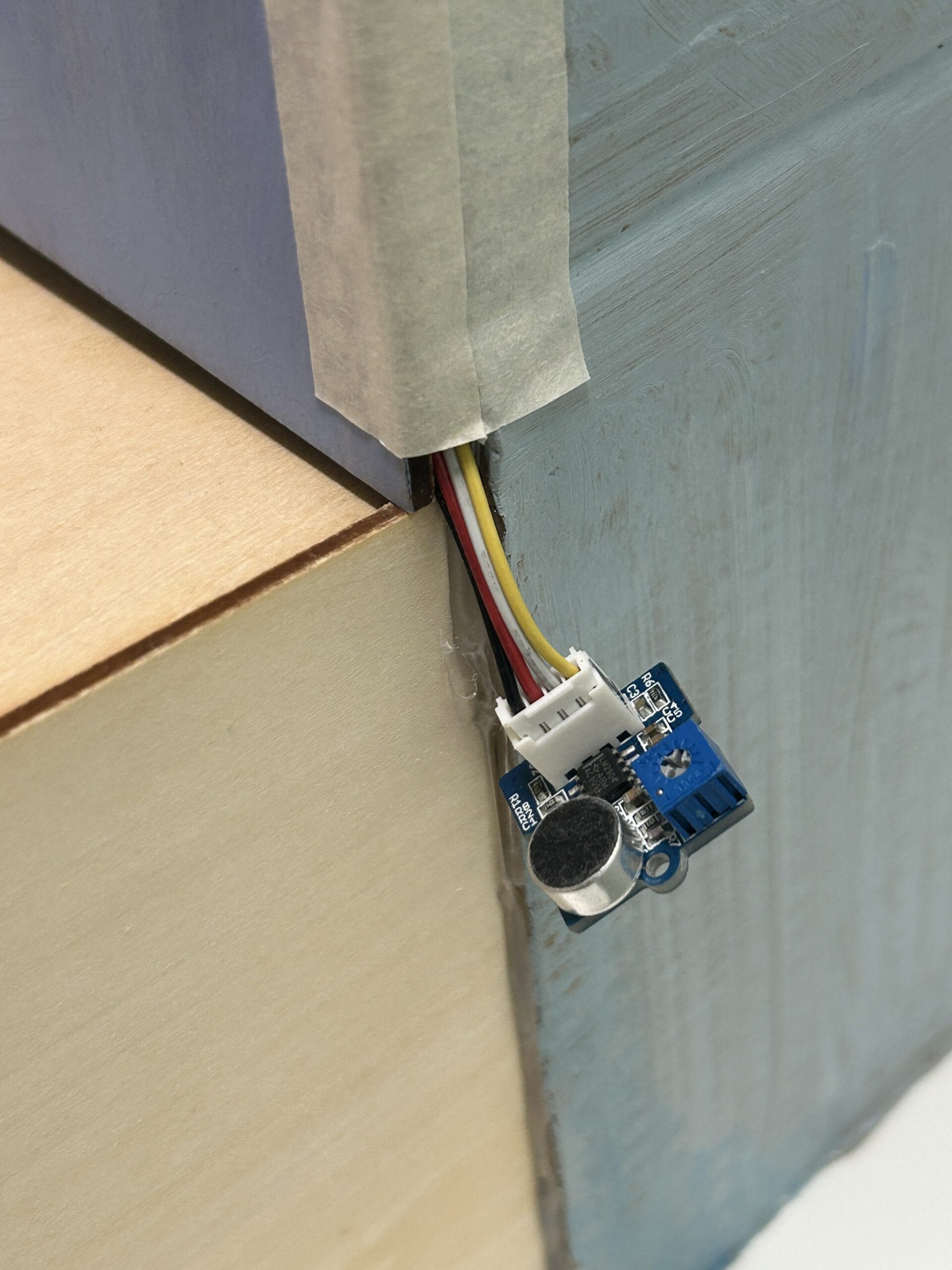
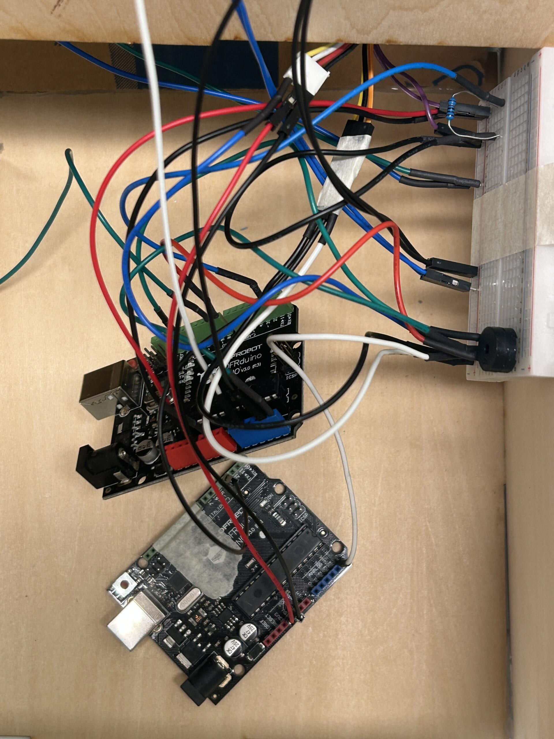
After that, it came to stage2, which was the shouting game. We used a microphone sensor to detect how loud the user shouted. We used the “map” function again to draw a balloon which consisted of an ellipse, a triangle and a line. In this way, the size of the balloon would change according to the volume. If their volume were loud enough, the LED strip would light up one by one, and two arrows would show up, directing people to go to the back side. This part was tricky, we initially intended to set up a stage3 to control the LED strips. However, the codes got too complicated, and the LED strip became unstable (it kept lighting or lit up random color). Therefore, we used another Arduino board and connected the microphone sensor to both the two Arduinos. We used the boolean function, “if” statements and “else if” statements to make sure that once the volume achieve the standard value, the LED strip would keep lighting up and would not stop even when the volume went low afterwards.
4) Glass Window
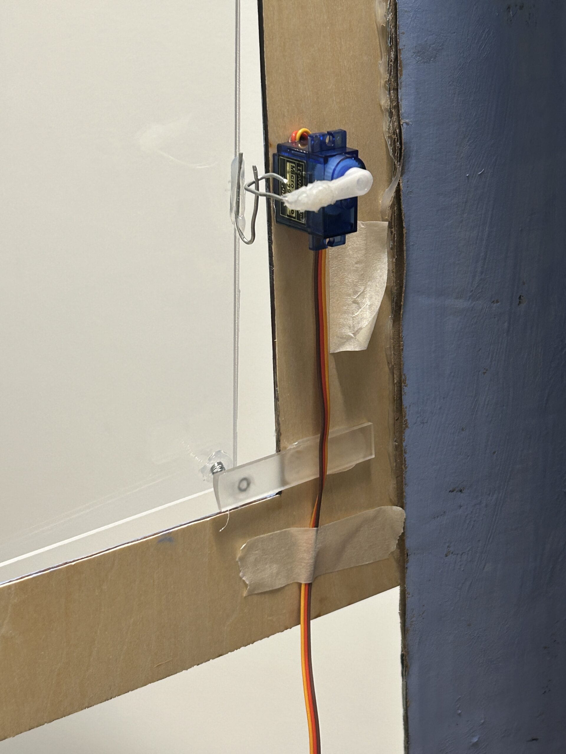
In this part, whenever the users pressed the back button, the glass window would open. To make a window that could be opened and closed, we first laser cut a transparent acrylic board. Then, we glued the sides of the acrylic board to a thick wire, cut a straw and wrapped it around the glued area to make it stronger. Next, we tapped the wire to the wooden frame so that the window could rotate. To lock and unlock the window, we bent the wires and made two little hooks. One was pasted with the glass window, and the other was pasted with a servo. When the servo rotated 90 degrees, the window could be unlocked. We also added a spring to make the glass window pop open. For the code, we again used the “if” statement and “while” statement to make sure that only after the button was released could the window be unlocked.
- CONCLUSIONS
Again, the goal of our project was to explore counter-intuitive interaction and get an insight into how feedback that not aligned with expectations can affect the interaction process. The project was aligned with the definition of interaction (including action and reaction), though our instructions led to a more complicated path. I think the project achieved its goal. During the final presentation, the IMA show and other interaction processes, we found that users have different reactions. Generally, their reactions can be divided into two kinds: (1) (relying on given instructions) read our instructions carefully, pressed a button and found that the one they wanted did not come out, played the games step by step to get the fortune cookie; 2) (probably did not read the instructions and wanted to explore the project by themselves) randomly choose a button and got confused, started to grab the cookies that fell down or pressing other buttons or kept asking or felt that the project did not work. Interestingly, nobody looked around the project before interacting, and nobody found out the button could directly open the door in their first interaction, but when we encouraged users to interact with it again, with some hints most of them would realize the shortcut. From the users’ behaviors, we learned many things about the interaction processes. Some of the users tended to explore the project by themselves first (though we have clear instructions on what to do in the first step), but they would not explore the project comprehensively (e.g. looking around before started), they would start from things in front of them (e.g. the six buttons at the front). And when unexpected happened, the users who tended to explore by themselves could be more flustered than the ones who tended to follow the instructions (e.g. they started to ask what to do next). This made me reflect our daily interactive designs. Though most of them are intuitive, the products must be intuitive enough to let users (either following the instructions or exploring by themselves) figure out the correct interactive process.
If we had more time, I think we could make some improvements by adding some light on to the shelves to make it look nicer. Also, LED lights can be added on the top of the shelves to indicate more clearly that the cookie user chose did not fell down. (We initially built the LEDs but finally got rid of them, because when the circuit was put into the vending machine, it did not work and we did not have time to fix it.) The LED light strip could also shine colorfully after the user pressed the back button. The microphone sensor could be built inside something shaped like a real microphone. Also, adding a camera to capture users’ facial expressions could help learn more about users’ behaviors.
The process of making our final project was also a process of consolidating what we’ve learnt throughout the semester as well as learning new practicable stuffs that the course did not cover. Our projects faced a lot of difficulties. Technically, we knew more about how to code and debug. Apart from that, I learned that when encountering difficulties that are really hard to overcome, sometimes take a break can help come up with new ideas to solve the problem. From our accomplishments, I found that we actually have lots of possibilities; sometimes we always feel that we can’t accomplish something, but after being pushed, we find that it can actually be done.
The project took us three weeks. I would like to express my sincere gratitude to Professor Inmi, Professor Gottfried, Professor Andy and Professor Rudi for their guidance and support. I would also like to thank Amelia, Kevin and Shengli for their warm help. Many thanks for my partner Emily, we laughed together, broke down together, stayed up for seven nights together, persisted together and overcame all those difficulties together. I am grateful for everyone who has supported and helped us over the past three weeks. I also appreciate the Matcha custard mochi and the whiskey ice cream in Drunk Baker that accompanied us for many desperate nights and ended up in our stomachs.
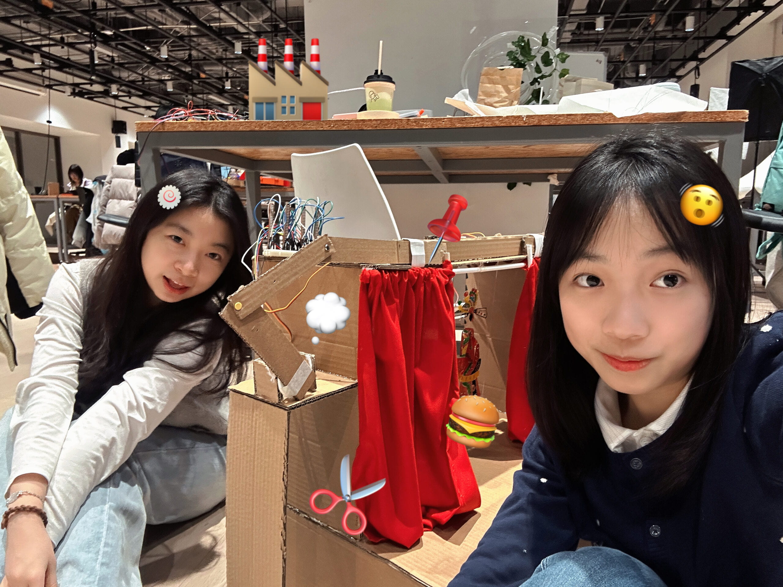
 (a selfie of me & Emily)
- DISASSEMBLY
- APPENDIX
1) Video
Link: https://drive.google.com/file/d/1n0MD6sKq5rwg1RHBHYAmHTSuq6b82moZ/view?usp=sharing
2)Codes
// Processing
import processing.serial.*;
Serial serialPort1; //first Arduino (servo motors, buttons)
Serial serialPort2; //second Arduino (potentiometers)
int NUM_OF_VALUES_FROM_ARDUINO1 = 1;
int NUM_OF_VALUES_FROM_ARDUINO2 = 5; /* CHANGE THIS ACCORDING TO YOUR PROJECT /
/ This array stores values from Arduino */
int arduino_values1[] = new int[NUM_OF_VALUES_FROM_ARDUINO1];
int arduino_values2[] = new int[NUM_OF_VALUES_FROM_ARDUINO2];
int state1;
int state2;
float a;
float b;
PImage photo1, photo2;
PFont myFont;
boolean shoutDetected = false;
int oldFrameCount;
void setup() {
size(1200, 800);
printArray(Serial.list());
// put the name of the serial port your Arduino is connected
// to in the line below – this should be the same as you’re
// using in the “Port” menu in the Arduino IDE
serialPort1 = new Serial(this, “/dev/cu.usbmodem1101”, 9600);
serialPort2 = new Serial(this, “/dev/cu.usbmodem1401”, 9600);
photo1 = loadImage(“balloon.png”);
photo2 = loadImage(“puzzle1.png”);
myFont = createFont(“Times New Roman”, 110);
}
void draw() {
getSerialData();
getSerialData2();
if(arduino_values1[0] == 0){
//interaction with the first Arduino is ongoing
background(0);
stroke(255);
textFont(myFont);
//textSize(50);
textAlign(CENTER, CENTER);
text(“Get your fortune”, width/2, height/2 – 65);
text(“by pressing ONE button”, width/2, height/2 + 65);
} else {
state2 = arduino_values2[3];
if (state2 == 1) {
background(0);
state1 = arduino_values2[0];
float x = map(arduino_values2[1], 0, 1023, 100, 620);
float y = map(arduino_values2[2], 0, 1023, -400, 250);
image(photo1, x, y);
image(photo2, 370, -50);
stroke(255);
textFont(myFont);
textSize(60);
text(“Want to get it”, 380, 120);
textSize(map(sin(frameCount/3), -1, 1, 30, 80));
text(“BACK?”, 380, 190);
oldFrameCount = frameCount;
} else if (state2 ==2) {
background(0);
stroke(255);
textFont(myFont);
text(“shout out loud to”, width/2, 170);
text(“get the one you chose”, width/2, 260);
if (frameCount >= oldFrameCount + 120) {
//sound visualization
float a = map(arduino_values2[4], 0, 70, 170, 1000);
float b = a + 70;
ellipse(width/2, height/2, a, b);
triangle(width/2, 400+ b/2, width/2 – 30, 430+ b/2, width/2 + 30, 430+ b/2);
stroke(255);
strokeWeight(2);
line(width/2, 430+ b/2, width/2, height);
if (arduino_values2[4] >= 120) {
shoutDetected = true;
}
if (shoutDetected == true) {
background(255);
fill(0);
noStroke();
triangle(350, 250, 200, 400, 350, 550);
triangle(850, 250, 1000, 400, 850, 550);
rect(350, 325, 150, 150);
rect(700, 325, 150, 150);
}
}
}
}
}
void getSerialData() {
while (serialPort1.available() > 0) {
String in = serialPort1.readStringUntil(10); // 10 = ‘\n’ Linefeed in ASCII
if (in != null) {
print(“From Arduino: ” + in);
String[] serialInArray = split(trim(in), “,”);
if (serialInArray.length == NUM_OF_VALUES_FROM_ARDUINO1) {
for (int i = 0; i < serialInArray.length; i++) {
arduino_values1[i] = int(serialInArray[i]);
}
}
}
}
}
void getSerialData2() {
while (serialPort2.available() > 0) {
String in = serialPort2.readStringUntil(10); // 10 = ‘\n’ Linefeed in ASCII
if (in != null) {
print(“From Arduino: ” + in);
String[] serialInArray = split(trim(in), “,”);
if (serialInArray.length == NUM_OF_VALUES_FROM_ARDUINO2) {
for (int i=0; i<serialInArray.length; i++) {
arduino_values2[i] = int(serialInArray[i]);
}
}
}
}
}
// Arduino1
#include <Servo.h>
// servos
Servo servo1;
Servo servo2;
Servo servo3;
Servo servo4;
Servo servo5;
Servo servo6;
// buttons
int pushButton1 = 2;
int pushButton2 = 3;
int pushButton3 = 4;
int pushButton4 = 5;
int pushButton5 = 6;
int pushButton6 = 7;
int buttonState1 = 0;
int buttonState2 = 0;
int buttonState3 = 0;
int buttonState4 = 0;
int buttonState5 = 0;
int buttonState6 = 0;
void setup() {
//buttons
pinMode(pushButton1, INPUT);
pinMode(pushButton2, INPUT);
pinMode(pushButton3, INPUT);
pinMode(pushButton4,INPUT);
pinMode(pushButton5,INPUT);
pinMode(pushButton6,INPUT);
// servos
servo1.attach(8);
servo2.attach(9);
servo3.attach(10);
servo4.attach(11);
servo5.attach(12);
servo6.attach(13);
servo1.write(5);
servo2.write(5);
servo3.write(5);
servo4.write(5);
servo5.write(5);
servo6.write(5);
Serial.begin(9600);
}
void loop() {
// read buttonState
buttonState1 = digitalRead(pushButton1);
buttonState2 = digitalRead(pushButton2);
buttonState3 = digitalRead(pushButton3);
buttonState4 = digitalRead(pushButton4);
buttonState5 = digitalRead(pushButton5);
buttonState6 = digitalRead(pushButton6);
// Serial.println(buttonState1);
// Serial.println(buttonState2);
// Serial.println(buttonState3);
// Serial.println(buttonState4);
// Serial.println(buttonState5);
// Serial.println(buttonState6);
if (buttonState1 == 1) {
while (buttonState1 == 0) {
delay(10);
}
delay(1000);
servo1.write(5);
servo2.write(150);
servo3.write(150);
servo4.write(150);
servo5.write(150);
servo6.write(150);
} else if (buttonState2 == 1) {
while (buttonState2 == 0) {
delay(10);
}
delay(1000);
servo1.write(150);
servo2.write(5);
servo3.write(150);
servo4.write(150);
servo5.write(150);
servo6.write(150);
} else if (buttonState3 == 1) {
while (buttonState3 == 0) {
delay(10);
}
delay(1000);
servo1.write(150);
servo2.write(150);
servo3.write(5);
servo4.write(150);
servo5.write(150);
servo6.write(150);
} else if (buttonState4 == 1) {
while (buttonState4 == 0) {
delay(10);
}
delay(1000);
servo1.write(150);
servo2.write(150);
servo3.write(150);
servo4.write(5);
servo5.write(150);
servo6.write(150);
} else if (buttonState5 == 1) {
while (buttonState5 == 0) {
delay(10);
}
delay(1000);
servo1.write(150);
servo2.write(150);
servo3.write(150);
servo4.write(150);
servo5.write(5);
servo6.write(150);
} else if (buttonState6 == 1) {
while (buttonState6 == 0) {
delay(10);
}
delay(1000);
servo1.write(150);
servo2.write(150);
servo3.write(150);
servo4.write(150);
servo5.write(150);
servo6.write(5);
}
if (buttonState1 == 1 || buttonState2 == 1 || buttonState3 == 1 || buttonState4 == 1 || buttonState5 == 1 || buttonState6 == 1){
Serial.print(“1”);
Serial.println();
}
}
// Arduino2
#include <Servo.h>
#include <FastLED.h>
#define NUM_LEDS 60
#define DATA_PIN 3 // the pin connected to the strip’s DIN
CRGB leds[NUM_LEDS];
//back button
int pushButton0 = 2;
//microphone sensor
int microphone;
int middle = NUM_LEDS/2;
int buttonState0;
//servo
Servo myservo;
#define NOTE_G4 392
#define NOTE_E4 330
#define NOTE_C4 262
// Notes in the melody:
int melody[] = {
NOTE_G4, NOTE_E4, NOTE_C4, NOTE_E4, NOTE_G4
};
// Note durations: 4 = quarter note, 8 = eighth note, etc.:
int noteDurations[] = {
8, 8, 8, 8, 2
};
int state1 = 1;
int state2 = 1;
bool playMelodyOnce = false; // Flag to play the melody once
void setup() {
Serial.begin(9600);
//LED strip
FastLED.addLeds<NEOPIXEL, DATA_PIN>(leds, NUM_LEDS);
//back button
pinMode(pushButton0, INPUT);
//servo
myservo.attach(9);
myservo.write(90);
}
void loop() {
if (state1 == 1){
state11();
}
if(state2 == 2){
state22();
}
//LED strip
fill_solid(leds, NUM_LEDS, CRGB::Black);
FastLED.show();
//back button
delay(1);
buttonState0 = digitalRead(2);
Serial.println(buttonState0);
//when the back button is pressed, the door opens
if (buttonState0 == 1) {
while (buttonState0 == 0) {
delay(10);
}
myservo.write(5);
}
}
void state11(){
// Read sensor values
int sensor0 = analogRead(A4);
int sensor1 = analogRead(A1);
microphone = analogRead(A5);
// Send values to Processing
Serial.print(state1);
Serial.print(“,”);
Serial.print(sensor0);
Serial.print(“,”); // Put a comma between sensor values
Serial.print(sensor1);
Serial.print(“,”);
Serial.print(state2);
Serial.print(“,”);
Serial.print(microphone);
Serial.println(); // Add linefeed after sending the last sensor value
// Delay to avoid communication latency
delay(100);
if (!playMelodyOnce && sensor0 >= 526 && sensor0 <= 536 && sensor1 >= 544 && sensor1 <= 556) {
playMelodyOnce = true; // Set the flag to play the melody once
playMelody();
state2 = 2;
}
}
void playMelody() {
// Iterate over the notes of the melody
for (int thisNote = 0; thisNote < 5; thisNote++) {
// Calculate the note duration
int noteDuration = 1000 / noteDurations[thisNote];
tone(8, melody[thisNote], noteDuration);
// Set a pause between notes
int pauseBetweenNotes = noteDuration * 1.30;
delay(pauseBetweenNotes);
// Stop the tone playing
noTone(8);
}
}
// Arduino3
#include <FastLED.h>
#define NUM_LEDS 60
#define DATA_PIN 3 // the pin connected to the strip’s DIN
CRGB leds[NUM_LEDS];
int middle = NUM_LEDS / 2;
int microphone;
bool ledState = false;
//int pushButton0 = 2;
//int buttonState0;
void setup() {
Serial.begin(9600);
FastLED.addLeds<NEOPIXEL, DATA_PIN>(leds, NUM_LEDS);
fill_solid(leds, NUM_LEDS, CRGB::Black);
FastLED.show();
// pinMode(pushButton0, INPUT);
}
void loop() {
// buttonState0 = digitalRead(2);
//Serial.println(buttonState0);
microphone = analogRead(A5);
Serial.println(microphone);
if (microphone >= 160 && ledState == false) {
lightUpLED();
ledState = true;
} else if (microphone >= 160 && ledState == true) {
lightUpLED();
} else if (microphone < 160 && ledState == true) {
lightUpLED();
}
}
void lightUpLED() {
ledState = true;
for (int i = 0; i <= middle; i = i + 1) {
leds[middle – i] = CRGB(241, 247, 75);
leds[middle + i] = CRGB(241, 247, 75);
FastLED.show();
delay(250);
}
fill_solid(leds, NUM_LEDS, CRGB::Black);
FastLED.show();
delay(300);
}
