Painting Robot
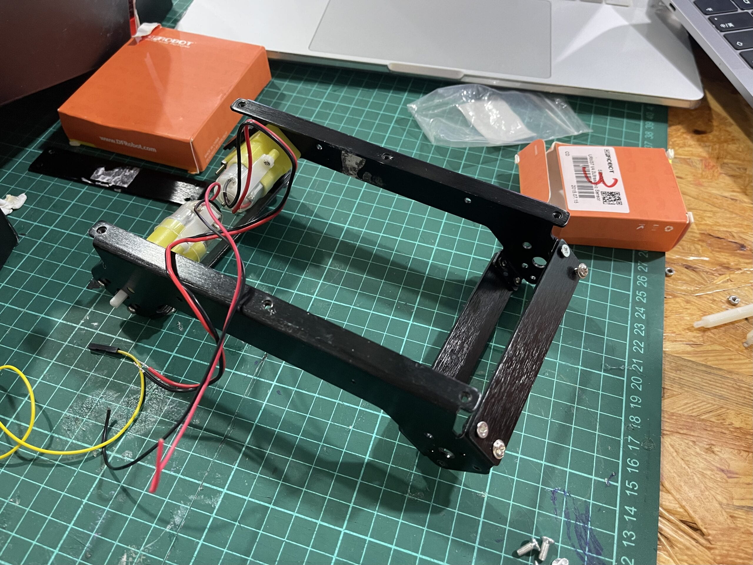
The first step is to assemble the frame together so that the robot can have a solid foundation to hold the circuit board. In our case, we only have 2 motors. So we decide to make it rear-wheel drive. No hot glue, no double-sided tape, we only use screws and bolts to do this.

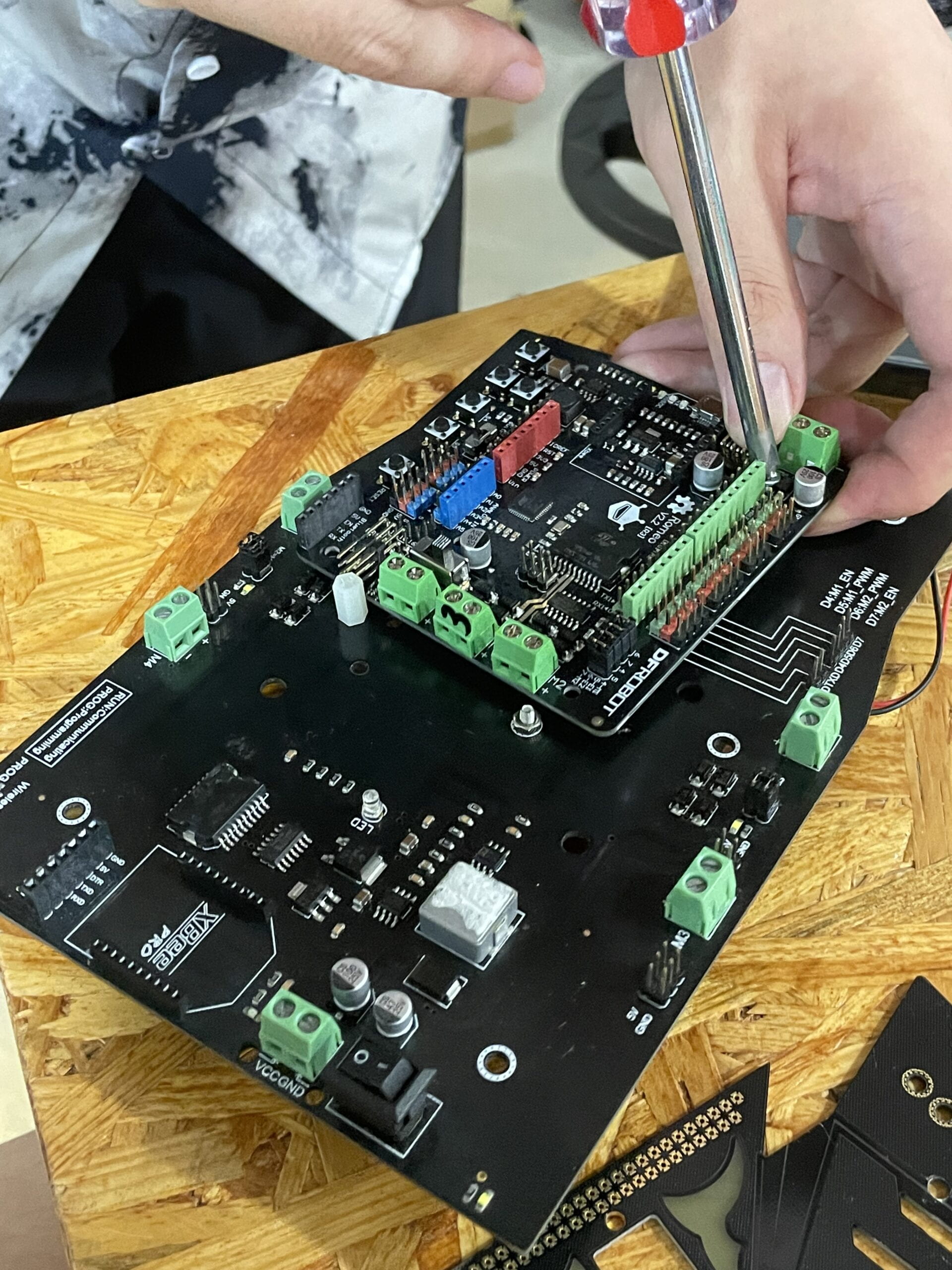
The second step is to make sure the Arduino Romeo V2.2 (which takes us some time to figure out we have a different version with the documentation) perfectly fits the bedplate. Similarly, screws and bolts are enough to make the shape holds.

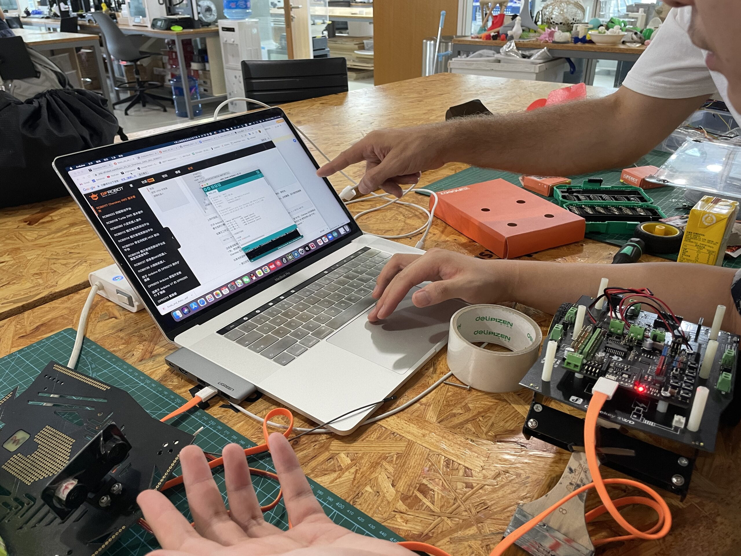
The third step is to upload the test code and see whether it works.

Here is the source code. And what we do is pretty simple, draw a circle here.
//Standard PWM DC control
int E1 = 5;     //M1 Speed Control
int E2 = 6;     //M2 Speed Control
int M1 = 4;    //M1 Direction Control
int M2 = 7;    //M1 Direction Control

///For previous Romeo, please use these pins.
//int E1 = 6;     //M1 Speed Control
//int E2 = 9;     //M2 Speed Control
//int M1 = 7;    //M1 Direction Control
//int M2 = 8;    //M1 Direction Control


void stop(void)                    //Stop
{
  digitalWrite(E1, LOW);
  digitalWrite(E2, LOW);
}
void advance(char a, char b)         //Move forward
{
  analogWrite (E1, a);     //PWM Speed Control
  digitalWrite(M1, HIGH);
  analogWrite (E2, b);
  digitalWrite(M2, HIGH);
}
void back_off (char a, char b)         //Move backward
{
  analogWrite (E1, a);
  digitalWrite(M1, LOW);
  analogWrite (E2, b);
  digitalWrite(M2, LOW);
}
void turn_L (char a, char b)            //Turn Left
{
  analogWrite (E1, a);
  digitalWrite(M1, LOW);
  analogWrite (E2, b);
  digitalWrite(M2, HIGH);
}
void turn_R (char a, char b)            //Turn Right
{
  analogWrite (E1, a);
  digitalWrite(M1, HIGH);
  analogWrite (E2, b);
  digitalWrite(M2, LOW);
}
void setup(void)
{
  int i;
  for (i = 4; i <= 7; i++)
    pinMode(i, OUTPUT);
  Serial.begin(19200);      //Set Baud Rate
  Serial.println("Run keyboard control");
}
void loop(void)
{
  back_off (255, 255);  //move forw
  delay(100);
  turn_R (100, 100);
  delay(100);

}
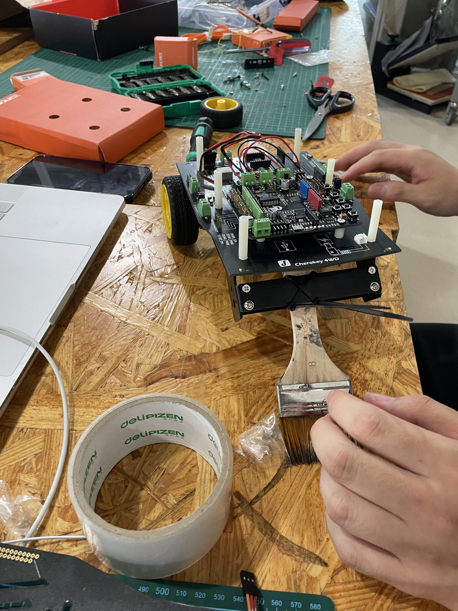
The third step is to use the zip tie to make the brush attached to the robot.

After finalizing all the configurations, this video shows the outcome.
Later I tried to implement more complex moving codes to draw a fancier shape and the result is ideal. Perhaps implementing an ultrasonic sensor will be a good idea. I will try it out in the later assignments.

