Recitation 1: Johnny
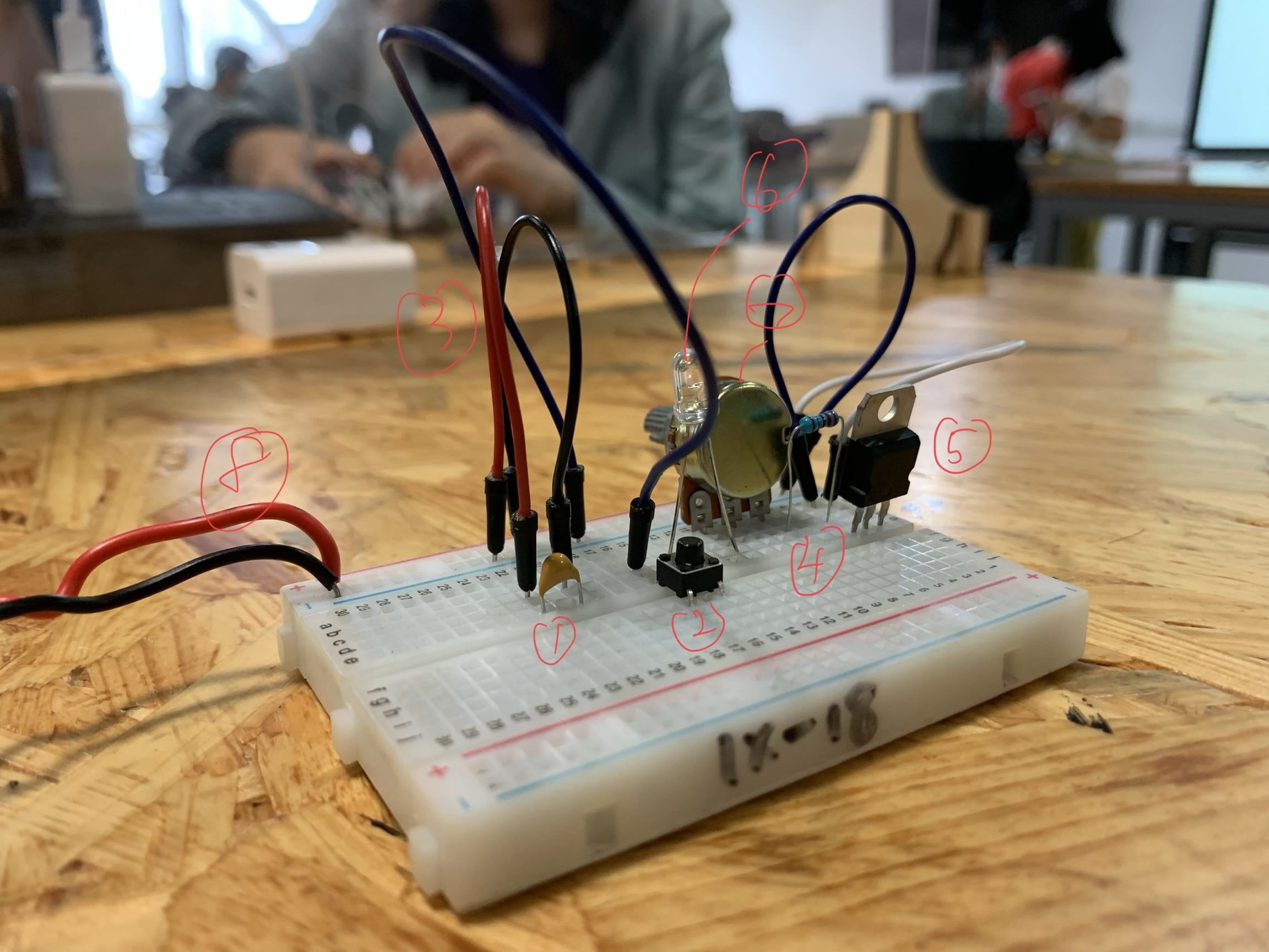
First, I am going to introduce all the components’ names and functions I used in this circuit.

- This is a capacitor. One head of it is linked to the positive pole of the battery and another is linked to the negative side. Without it, the LED won’t light up.
- This is a switch and is used to control whether there is electricity going through the whole circuit.
- These are wires. They are used to connect the whole circuit as a whole.
- This is resistance with a specific number showing how big it will influence the electricity.
- This is a voltage regulator. I have never seen this device before. But I think it is used to distribute electricity to different branches of this circuit.
- This is a small LED and if there is electricity running through it, it will light up. Mine is a one which can emit beautiful blue light.
- This is a variable resistor. You can change its number of resistance by switching the buttons on it. If you gradually turn it from the smallest to the bigger side, you can see the LED’s light is fading away.
- This is linked to a 12V power.
All my three circuits run very well and I take 2 shot videos of them
Though the results seem to be very nice, the process to build it is full of difficulties. At first, I don’t even understand the pictures using abstract representations. I mean I know every single component of it, but I have no idea how to put all these things together. I have never encountered a physical capacitor and voltage regulator. I don’t know how to install them on the breadboard. So I call the learning assistant for help and soon they give me much practical knowledge about their usages and how to plug them on the board. After I have finished the first version of my project, I turn on the power and click the switch. There is good news as well as bad news. The good news is that the LED successfully lights up while the bad one is that it has some smoke over it. So I turn off the power immediately. Not knowing what had happened, I was so puzzled about where went wrong. So again, I turn to the LA for help. (They are so helpful and nice. I really appreciate their help) Together, we have found that the switch is in the wrong direction. Because the switch’s shape is a square, I have put it in the wrong direction. So I rotate it for 90 degrees and everything is going well.
Then I am going to answer 2 questions.
A to Q1
I think the whole process of building the project includes interactivity. First, I was given instructions on how to build the circuit. And this is the step that I receive information from the outside world. When I was constructing the circus, it is similar to the step of me thinking and reacting to it. This is the angle of myself and the given task. When we only look at the circuit, the interactive part is the switch. By choosing to press the button or not, we can control whether the LED will light up. So the device can react to the outside simulation and meanwhile give the feedback by lighting up the LED or not. As far as I am concerned, this can be defined as a low level of interactivity.
A to Q2
From my point of view, we can integrate these two things together and physical computing might make lots of interactive designs come true. As in the video, the eye writer is an example of how physical computing can be the method to realize the dream of drawing only by eyes. I remember last class we have seen a design using the camera to catch the picture in front of the device and it will imitate the pattern by adjusting the angles of wooden boards. I believe it also uses physical computing as the controlling system behind it. In conclusion, physical computing provides artists with a new method to realize and accomplish their design.

