Recitation 8: Serial Communication

Recitation Friday!In this recitation,I would send data from Arduino to Processing and vice versa by using serial communication. 

Task #1:  Make a Processing Etch-A-Sketch

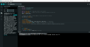
The first step went well.I built the circuit with two potentiometers. Based on the example of SendMultipleValues,I added another variable called sensorValue2 to send the second potentiometer’s serial information to the Processing.Here is the code of Arduino:

#include “SerialRecord.h”

// Change this number to send a different number of values
SerialRecord writer(2);

void setup() {
Serial.begin(9600);
}

void loop() {
int sensorValue = analogRead(A0);
int sensorValue2 = analogRead(A1);

writer[0] = sensorValue;
writer[1]= sensorValue2;
writer.send();

delay(10);
}
 

Just like an Etch-A-Sketch, one potentiometer controlled the circle’s x-axis movement, and the other controlled the circle’s y-axis movement. 
However,when I wanted to change the circles into lines,some problems occurred.

The first problem was that the start point of the line stuck at the top left corner.Then I fixed the problem by substituting the new x position for the old x position.So was the y position.

The second problem was that the track of the lines wasn’t marked.So I put the background setting in void setup rather than void draw.

Here was how users could draw by using the two potentiometers.The code is attached below.

import processing.serial.*;
import osteele.processing.SerialRecord.*;

Serial serialPort;
SerialRecord serialRecord;
float oldx;
float oldy;

void setup() {
   background(0);
  size(500, 500);
 
  String serialPortName = SerialUtils.findArduinoPort();
  serialPort = new Serial(this, serialPortName, 9600);

  // If the Arduino sketch sends a different number of values, modify the number
  // `2` on the next line to match the number of values that it sends.
  serialRecord = new SerialRecord(this, serialPort, 2);
}

void draw() {

  serialRecord.read();
  int value1 = serialRecord.values[0];
  int value2 = serialRecord.values[1];

  float x = map(value1, 0, 1024, 0, width);
  float y = map(value2, 0, 1024, 0, height);
  stroke(255);
  strokeWeight(15);
  line(oldx,oldy,x,y);
  oldx=x;
  oldy=y;
}

Task #2

My pair teammate is Sid.At first,we both worked out how to design the code of the bouncing ball without connecting the motors.

Here was my way of designing the bouncing ball.

int x=50;
int xdirection=1;
void setup() {
  fullScreen();
  background(0);
  
  
}

void draw() {
  background(0);
  circle(x,height/2,50);
  x=x+5*xdirection;
  if (x>width-50||x<50){
    xdirection*=-1;}
  
}

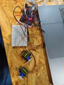
Nevertheless,we did spend some time on the code of spinning the two motors according to the position of the ball.We had problems such as only one motor rotated or the angle of the motor went wrong.Finally,we managed to deal with the problem by revising in the code.After several tests,the motors managed to spin at the right time(when the ball hit the edges) and right angle,just like this:
/*
ReceiveMultipleValues

This sketch repeatedly receives a record that contains a single value, and
uses it to control the builtin LED. The value should be 0 or 1.

This sketch pairs well with the SendSingleValue example from the Processing
SerialRecord library <https://osteele.github.io/Processing_SerialRecord/>.

You can also interact with this sketch from the Serial Monitor. Enter
`100,200` into the text area at the top, and press “Send”. Then enter `!e` to
ask the Arduino to send back the last values it received.

by Oliver Steele, 2020-2022

This example code is in the public domain.
*/

#include “SerialRecord.h”

// Change this number to the number of values you want to receive
SerialRecord reader(1);

#include <Servo.h>

Servo myservo; // create servo object to control a servo
Servo myservo2;

int potpin = A0; // analog pin used to connect the potentiometer
int val; // variable to read the value from the analog pin

void setup() {
Serial.begin(9600);
myservo.attach(9);
myservo2.attach(10);
}

void loop() {
reader.read();
//Serial.println(reader[0]);
val = 100;
if (reader[0] > 1420) {
myservo.write(val);
}
else if (reader[0] > 1400){
myservo.write(val – 100);
}
if (reader[0] < 10) {
myservo2.write(val);
}
else {
myservo2.write(val – 100);
}
//delay(20); // reads the value of the potentiometer (value between 0 and 1023) // scale it for use with the servo (value between 0 and 180)
// sets the servo position according to the scaled value
}
Recitation 7: Neopixel Music Visualization

Recitaion Friday!Today,I’m about to use the Neopixel to visualize the music codes in Processing.

Task #1: Test the NeoPixel

Task #2: Use my computer to light up NeoPixels

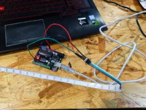
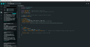
Here was how I sent values in a Comma Separated Value protocol (CSV) in the Arduino. 

Task #3: Add Music!

For this task,I substituted drum audios for the original music.Later,I changed several settings such as the colors of the circles and background.

Here was how it worked.Also,my code is attached below.

Processing:

import processing.serial.*;
import osteele.processing.SerialRecord.*;

Serial serialPort;
SerialRecord serialRecord;

int W;         //width of the tiles
int NUM = 60;  //amount of pixels
int[] r = new int[NUM]; //red of each tile
int[] g = new int[NUM]; //red of each tile
int[] b = new int[NUM]; //red of each tile

void setup() {
  size(600, 200);
  W = width/NUM;
  
  String serialPortName = SerialUtils.findArduinoPort();
  serialPort = new Serial(this, serialPortName, 9600);
  serialRecord = new SerialRecord(this, serialPort, 4);
  serialRecord.logToCanvas(false);
  rectMode(CENTER);
}

void draw() {
  background(0);
  for (int i=0; i<NUM; i ++) {
    fill(r[i], g[i], b[i]);
    rect(i * W + W/2, height/2, 10, 10);
  }

 if (mousePressed == true) {
    int n = floor(constrain(mouseX/W , 0, NUM-1));

    r[n] = floor(random(255));
    g[n] = floor(random(255));
    b[n] = floor(random(255));

    serialRecord.values[0] = n;     // which pixel we change (0-59)
    serialRecord.values[1] = r[n];  // how much red (0-255)
    serialRecord.values[2] = g[n];  // how much green (0-255)
    serialRecord.values[3] = b[n];  // how much blue (0-255)
    serialRecord.send();            // send it!
  }

}

Arduino:

#include <FastLED.h>
#define NUM_LEDS 30 // How many leds on your strip?
#define DATA_PIN 3
CRGB leds[NUM_LEDS];
void setup() {
  Serial.begin(9600);
  FastLED.addLeds<NEOPIXEL, DATA_PIN>(leds, NUM_LEDS);
}
void loop() {
  if (Serial.available() > 0) {
    char in = Serial.read();
    if (in == ‘R’) {
      // set all LEDs to red on R
      for (int i = 0; i < 30; i=i+1) {
        leds[i] = CRGB(10, 0, 0);
      }
      FastLED.show();
    }
    if (in == ‘G’) {
      // set all LEDs to green on G
      for (int i = 0; i < 30; i=i+1) {
        leds[i] = CRGB(0, 10, 0);
      }
      FastLED.show();
    }
  }
}

Unfortunately,I had spent too much time in the coding of Task 2 so that I didn’t have enough time for further testing in the last step.Still,since I had learnt the basic logic of it and had succeeded in the visualization of one light,I would definitely try to revise and improve the process of visualization in later works.

Final Project: Research

Just as Ernest Edmonds mentioned,”there are three kinds of engagement:Attracting,sustaining,relating”(Edmonds,12).In the article Art,Interaction and Engagement,he divided interavtive art systems into four situations which were termed”Static”,”Dynamic-Passive”,”Dynamic-Interactive” and “Dynamic-Interactive(Varying).The last two situations are when the works are influenced by the audience and they are closely related to the artifact that I would like to create.He also simplified four kinds of interactive art systems into”Responding,varying,influencing and communicating”(Edmonds,13).

From my point of view,interaction means acting with each other ,whether it was the acting between people,computers or between people and computers.More importantly,this was a two-way acting,which meant both sides had to respond to the other’s reactions.Besides,interaction should be something that is playable or subjected to change.Hence,a successful interactive experience should match my definition of interaction.And I think the prompt also showed idea that was in tune with my thoughts”Make an experience where the user sees the system’s response, and takes more action in response, in a continuous loop“.And here I will show two examples to express further.

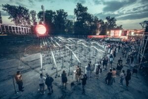
The first project is is a device which uses wires to connect a helium-filled sphere with 15 drums.As the people play the drum,the sounds are converted into light waves and then reach the sphere.When the sphere receive the signal of light waves,it will show flexible points on the screen.Of greater interest is that the intensity of points depends on the speed and intensity of the people’s drumming.During the process,it’s not hard to find that not only the sphere but also people act–for the former,it’s about receiving the signal and changing it into variable images;for the latter,it’s about playing drums and watching the changes of image.As the action goes back and forth,the two sides’ respondings match my definiton of interaction,which is”acting with each other”.It’s also self-evident that the project is subjected to change since the waves vary when the users hit the drum with different paces and intensities.So it’s definitely a successful interactive experience.

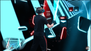
The second project is a VR game called Beat Saber.In the game,the game use two devices that looked like swords to cut the cubes while following the rhythm and the music.Here,the VR device showed the user different cubes as instructions for “hitting”.Then the user make actions based on the instructions.After “hitting” the cubes,new animations on the screens would appear to let the user notice that he had successfully hit the cubes in the game.Through this circulation as well as two-way acting,the user can interact with the VR device and achieve great fun,which fits Ernest’s ideas of”Responding,varying,influencing and communicating”(Edmonds,13).Therefore,I regard it as a successful interactive experience.

Reference List

1.Edmonds E. Art, Interaction and Engagement. 2011 15th International Conference on Information Visualisation, Information Visualisation (IV), 2011 15th International Conference on. July 2011:451-456. doi:10.1109/IV.2011.73

2.The prompt of Final Project:https://wp.nyu.edu/shanghai-ima-interaction-lab/final-project/

3.Peter Erskine’s CROMOS_ Solar Spectrum Rainbow Art,Peter Erskine    Mana   https://www.manamana.net/video/detail?id=70417#!zh

4.Josh Dub’s Youtube Video:THIS BEAT SABER LEVEL IS INSANE (3000+ NOTES) https://www.youtube.com/watch?v=3ehSPtWoiuc

Recitation 6: Animating an Interactive Poster

Recitation friday!This time,I’m about to design an interactive poster for the IMA Fall 22 End-Of-Semester Show.

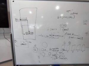
Based on my original design in recitation 5,I made some adjustments and figured out the logic of coding during the recitation class with the help of Margaret.

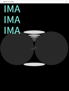
And this is the final work and its code after finishing the three homework tasks:

(Everytime the mouse clicked,the size of the rotating circle would change.And the extent of change was based on when the mouse clicked.)

float a;
float c;
float d;
void setup() {
  size(768, 1024);
  c = 10;
  d = 0.5;
}

void draw() {
  background(0);
  otherCircles();  
  textSize(120);
  fill(#8AF5E7);
  text("IMA", 40, 100);
  fill(#8AF5E7);
  text("IMA", 40, 250);
  fill(#8AF5E7);
  text("IMA", 40, 400);
  textSize(60);
  text("Fall 22 ",330,100);
  text("End-Of-Semester",330,180);
  text("Show",330,260);
  textSize(45);
  text("8th floor",530,800);
  text("Dec.16th",530,850);
  text("6-8 pm",530,900);
  fill(255);
  a = 5+millis()/1000.*PI;
  c = c+d;
  circle(width/2+(width/3)*cos(a),20+height/2-100*(sin(a)),2*c);
   if (cos(a)<0){
    d = 0.5;}
   else{
     d = -0.5;}
 
  println(sin(a), d);
    
}

void otherCircles() {
  fill(255, 220);
  ellipse(380, 679, 240, 40);
  fill(255, 40);
  circle(190, 500, 377);
  circle(570, 500, 377);

  stroke(0);
  strokeWeight(1);
  fill(255, 220);
  ellipse(380, 320, 240, 40);
  fill(255, 180);
  ellipse(380, 355, 140, 23);
  fill(255, 160);
  ellipse(380, 375, 100, 17);
  fill(255, 140);
  ellipse(380, 395, 65, 13);
  fill(255, 120);
  ellipse(380, 410, 48, 10);
  fill(255, 100);
  ellipse(380, 423, 38, 8);

  fill(255);
  circle(random(340,418), random(480,515), 4);
  circle(random(340,418), random(480,515), 4);
  circle(random(340,418), random(480,515), 4);
  circle(random(340,418), random(480,515), 4);
  circle(random(340,418), random(480,515), 4);
  circle(random(340,418), random(480,515), 4);
  circle(random(340,418), random(480,515), 4);
  circle(random(340,418), random(480,515), 4);
  circle(random(340,418), random(480,515), 4);
 
}

void mouseClicked() {
  c=-c;
}

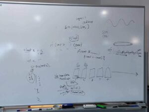
The most struggling as well as interesting part was the circle moving along an elliptical trajectory.I spent some time talking with Margaret and an Learning Assistant to find out the appropriate way. To make the movement more fluently, I chose millis() instead of framecount().Since the X of the circle was moving side to side and the Y of the circle was moving back and forth,the graph of sin and cos perfectly fitted.However,it did take me much time to calculate the relations between X,Y and Size.And it was important to multiply a PI inside the sin and cos so that it was easier to count and calculate.I was glad that I succeeded after lots of attempts and adjustments.

Recitation 5: Processing Basics

Recitation Friday!!Today,it’s my first time to draw an image in Processing based on a photograph that inspired me.

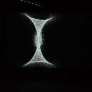
The day before recitation,I visited the Institude of Contemporary Art in NYUSH and there was an exhibition.When I was visiting the artwork of a video,I was deeply impressed by the beauty of shape and light.Therefore,I took this picture.Since the picture had an aesthetic quality and geomatric features,it perfectly matched the prompt of the recitation.

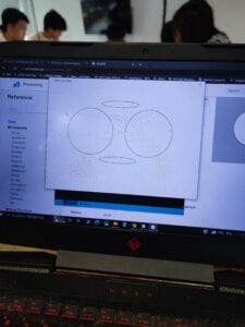
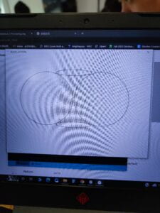
In the Processing,my general design was to use two ellipses on the top and the bottom and put two circles on left and right to create the curves.

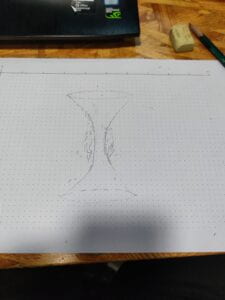
Firstly, I roughly sketched on the paper to set the position and size of graphs.

Next, I coded two ellipses and two circles.

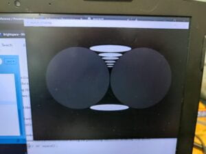
Oops…It seemed that something went wrong in the calculation.So I reset the position and size of the circles.To make the joint of the two shapes more fluent,I also set the strokeweight as 1.

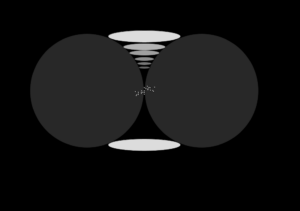
In order to enhance the visual effects and to make it more three-dimensinal,I painted the background and circles in black.Based on the original work,I substituted small ellipses for the small white circular rings.What’s more,I only put the small ellipses on the top half while the bottom half remained black because asymmetry was also a helpful way to promote the aesthetic quality.

Lastly,I added several white points in the middle.At first,I used the code of point but it was too small to be seen.As a result,I chose circles with small sizes to meet my requirement.Here is the final work and its code.

void setup() {
  background(0);
  size(1000, 700);

  fill(255, 220);
  ellipse(480, 479, 240, 40);
  fill(255, 40);
  circle(290, 300, 377);
  circle(670, 300, 377);

  stroke(0);
  strokeWeight(1);
  fill(255, 220);
  ellipse(480, 120, 240, 40);
  fill(255, 180);
  ellipse(480, 155, 140, 23);
  fill(255, 160);
  ellipse(480, 175, 100, 17);
  fill(255, 140);
  ellipse(480, 195, 65, 13);
  fill(255, 120);
  ellipse(480, 210, 48, 10);
  fill(255, 100);
  ellipse(480, 223, 38, 8);

  fill(255);
  circle(500, 290, 4);
  circle(490, 295, 4);
  circle(480, 300, 4);
  circle(470, 305, 4);
  circle(460, 310, 4);
  circle(500, 298, 4);
  circle(490, 285, 4);
  circle(480, 289, 4);
  circle(475, 305, 4);
  circle(480, 290, 4);
  circle(492, 297, 4);
  circle(480, 305, 4);
  circle(470, 309, 4);
  circle(460, 312, 4);
  circle(470, 299, 4);
  circle(495, 289, 4);
  circle(485, 292, 4);
  circle(471, 300, 4);
  circle(510, 302, 4);
  circle(499, 290, 4);
  circle(514, 288, 4);
  circle(450, 303, 4);
  circle(508, 299, 4);
  circle(493, 294, 4);
  circle(455, 313, 4);
  circle(453, 316, 4);
  circle(480, 311, 4);
  circle(460, 305, 4);
}

Due to the restriction of time and skills, I didn’t go further to explore the step 4.But I supposed in the following practice or works,I would definitely have a try based on the ideas in the prompts.

Comparing to the original artwork,my works was more of a simplified version since I kept the main design while deleting the complex white circular rings .Meanwhile,I added more ellipses in the top half and used several small circles in the middle to create nebula-like graphs.I also made them tilt. From my point of view,using Processing to draw wasn’t the most ideal way to realize my design because the curves and circular rings were hard to draw with codes for a beginner like me.(Or it was because I lacked the skills in Processing) Still,it was a fun experience.