Final Project: Research

Just as Ernest Edmonds mentioned,”there are three kinds of engagement:Attracting,sustaining,relating”(Edmonds,12).In the article Art,Interaction and Engagement,he divided interavtive art systems into four situations which were termed”Static”,”Dynamic-Passive”,”Dynamic-Interactive” and “Dynamic-Interactive(Varying).The last two situations are when the works are influenced by the audience and they are closely related to the artifact that I would like to create.He also simplified four kinds of interactive art systems into”Responding,varying,influencing and communicating”(Edmonds,13).

From my point of view,interaction means acting with each other ,whether it was the acting between people,computers or between people and computers.More importantly,this was a two-way acting,which meant both sides had to respond to the other’s reactions.Besides,interaction should be something that is playable or subjected to change.Hence,a successful interactive experience should match my definition of interaction.And I think the prompt also showed idea that was in tune with my thoughts”Make an experience where the user sees the system’s response, and takes more action in response, in a continuous loop“.And here I will show two examples to express further.

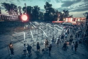
The first project is is a device which uses wires to connect a helium-filled sphere with 15 drums.As the people play the drum,the sounds are converted into light waves and then reach the sphere.When the sphere receive the signal of light waves,it will show flexible points on the screen.Of greater interest is that the intensity of points depends on the speed and intensity of the people’s drumming.During the process,it’s not hard to find that not only the sphere but also people act–for the former,it’s about receiving the signal and changing it into variable images;for the latter,it’s about playing drums and watching the changes of image.As the action goes back and forth,the two sides’ respondings match my definiton of interaction,which is”acting with each other”.It’s also self-evident that the project is subjected to change since the waves vary when the users hit the drum with different paces and intensities.So it’s definitely a successful interactive experience.

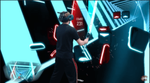
The second project is a VR game called Beat Saber.In the game,the game use two devices that looked like swords to cut the cubes while following the rhythm and the music.Here,the VR device showed the user different cubes as instructions for “hitting”.Then the user make actions based on the instructions.After “hitting” the cubes,new animations on the screens would appear to let the user notice that he had successfully hit the cubes in the game.Through this circulation as well as two-way acting,the user can interact with the VR device and achieve great fun,which fits Ernest’s ideas of”Responding,varying,influencing and communicating”(Edmonds,13).Therefore,I regard it as a successful interactive experience.

Reference List

1.Edmonds E. Art, Interaction and Engagement. 2011 15th International Conference on Information Visualisation, Information Visualisation (IV), 2011 15th International Conference on. July 2011:451-456. doi:10.1109/IV.2011.73

2.The prompt of Final Project:https://wp.nyu.edu/shanghai-ima-interaction-lab/final-project/

3.Peter Erskine’s CROMOS_ Solar Spectrum Rainbow Art,Peter Erskine    Mana   https://www.manamana.net/video/detail?id=70417#!zh

4.Josh Dub’s Youtube Video:THIS BEAT SABER LEVEL IS INSANE (3000+ NOTES) https://www.youtube.com/watch?v=3ehSPtWoiuc

Recitation 6: Animating an Interactive Poster

Recitation friday!This time,I’m about to design an interactive poster for the IMA Fall 22 End-Of-Semester Show.

Based on my original design in recitation 5,I made some adjustments and figured out the logic of coding during the recitation class with the help of Margaret.

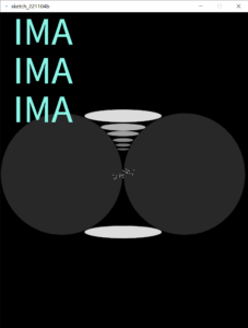
And this is the final work and its code after finishing the three homework tasks:

(Everytime the mouse clicked,the size of the rotating circle would change.And the extent of change was based on when the mouse clicked.)

float a;
float c;
float d;
void setup() {
  size(768, 1024);
  c = 10;
  d = 0.5;
}

void draw() {
  background(0);
  otherCircles();  
  textSize(120);
  fill(#8AF5E7);
  text("IMA", 40, 100);
  fill(#8AF5E7);
  text("IMA", 40, 250);
  fill(#8AF5E7);
  text("IMA", 40, 400);
  textSize(60);
  text("Fall 22 ",330,100);
  text("End-Of-Semester",330,180);
  text("Show",330,260);
  textSize(45);
  text("8th floor",530,800);
  text("Dec.16th",530,850);
  text("6-8 pm",530,900);
  fill(255);
  a = 5+millis()/1000.*PI;
  c = c+d;
  circle(width/2+(width/3)*cos(a),20+height/2-100*(sin(a)),2*c);
   if (cos(a)<0){
    d = 0.5;}
   else{
     d = -0.5;}
 
  println(sin(a), d);
    
}

void otherCircles() {
  fill(255, 220);
  ellipse(380, 679, 240, 40);
  fill(255, 40);
  circle(190, 500, 377);
  circle(570, 500, 377);

  stroke(0);
  strokeWeight(1);
  fill(255, 220);
  ellipse(380, 320, 240, 40);
  fill(255, 180);
  ellipse(380, 355, 140, 23);
  fill(255, 160);
  ellipse(380, 375, 100, 17);
  fill(255, 140);
  ellipse(380, 395, 65, 13);
  fill(255, 120);
  ellipse(380, 410, 48, 10);
  fill(255, 100);
  ellipse(380, 423, 38, 8);

  fill(255);
  circle(random(340,418), random(480,515), 4);
  circle(random(340,418), random(480,515), 4);
  circle(random(340,418), random(480,515), 4);
  circle(random(340,418), random(480,515), 4);
  circle(random(340,418), random(480,515), 4);
  circle(random(340,418), random(480,515), 4);
  circle(random(340,418), random(480,515), 4);
  circle(random(340,418), random(480,515), 4);
  circle(random(340,418), random(480,515), 4);
 
}

void mouseClicked() {
  c=-c;
}

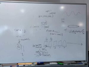
The most struggling as well as interesting part was the circle moving along an elliptical trajectory.I spent some time talking with Margaret and an Learning Assistant to find out the appropriate way. To make the movement more fluently, I chose millis() instead of framecount().Since the X of the circle was moving side to side and the Y of the circle was moving back and forth,the graph of sin and cos perfectly fitted.However,it did take me much time to calculate the relations between X,Y and Size.And it was important to multiply a PI inside the sin and cos so that it was easier to count and calculate.I was glad that I succeeded after lots of attempts and adjustments.

Recitation 5: Processing Basics

Recitation Friday!!Today,it’s my first time to draw an image in Processing based on a photograph that inspired me.

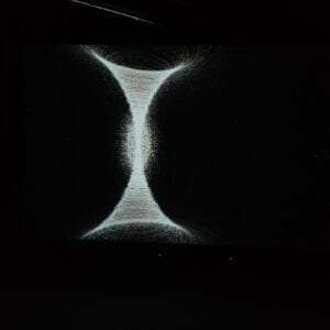
The day before recitation,I visited the Institude of Contemporary Art in NYUSH and there was an exhibition.When I was visiting the artwork of a video,I was deeply impressed by the beauty of shape and light.Therefore,I took this picture.Since the picture had an aesthetic quality and geomatric features,it perfectly matched the prompt of the recitation.

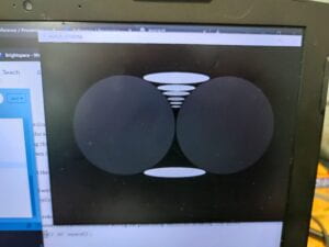
In the Processing,my general design was to use two ellipses on the top and the bottom and put two circles on left and right to create the curves.

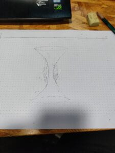
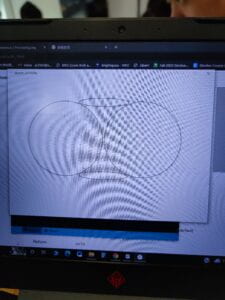
Firstly, I roughly sketched on the paper to set the position and size of graphs.

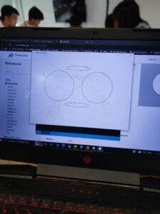
Next, I coded two ellipses and two circles.

Oops…It seemed that something went wrong in the calculation.So I reset the position and size of the circles.To make the joint of the two shapes more fluent,I also set the strokeweight as 1.

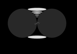
In order to enhance the visual effects and to make it more three-dimensinal,I painted the background and circles in black.Based on the original work,I substituted small ellipses for the small white circular rings.What’s more,I only put the small ellipses on the top half while the bottom half remained black because asymmetry was also a helpful way to promote the aesthetic quality.

Lastly,I added several white points in the middle.At first,I used the code of point but it was too small to be seen.As a result,I chose circles with small sizes to meet my requirement.Here is the final work and its code.

void setup() {
  background(0);
  size(1000, 700);

  fill(255, 220);
  ellipse(480, 479, 240, 40);
  fill(255, 40);
  circle(290, 300, 377);
  circle(670, 300, 377);

  stroke(0);
  strokeWeight(1);
  fill(255, 220);
  ellipse(480, 120, 240, 40);
  fill(255, 180);
  ellipse(480, 155, 140, 23);
  fill(255, 160);
  ellipse(480, 175, 100, 17);
  fill(255, 140);
  ellipse(480, 195, 65, 13);
  fill(255, 120);
  ellipse(480, 210, 48, 10);
  fill(255, 100);
  ellipse(480, 223, 38, 8);

  fill(255);
  circle(500, 290, 4);
  circle(490, 295, 4);
  circle(480, 300, 4);
  circle(470, 305, 4);
  circle(460, 310, 4);
  circle(500, 298, 4);
  circle(490, 285, 4);
  circle(480, 289, 4);
  circle(475, 305, 4);
  circle(480, 290, 4);
  circle(492, 297, 4);
  circle(480, 305, 4);
  circle(470, 309, 4);
  circle(460, 312, 4);
  circle(470, 299, 4);
  circle(495, 289, 4);
  circle(485, 292, 4);
  circle(471, 300, 4);
  circle(510, 302, 4);
  circle(499, 290, 4);
  circle(514, 288, 4);
  circle(450, 303, 4);
  circle(508, 299, 4);
  circle(493, 294, 4);
  circle(455, 313, 4);
  circle(453, 316, 4);
  circle(480, 311, 4);
  circle(460, 305, 4);
}

Due to the restriction of time and skills, I didn’t go further to explore the step 4.But I supposed in the following practice or works,I would definitely have a try based on the ideas in the prompts.

Comparing to the original artwork,my works was more of a simplified version since I kept the main design while deleting the complex white circular rings .Meanwhile,I added more ellipses in the top half and used several small circles in the middle to create nebula-like graphs.I also made them tilt. From my point of view,using Processing to draw wasn’t the most ideal way to realize my design because the curves and circular rings were hard to draw with codes for a beginner like me.(Or it was because I lacked the skills in Processing) Still,it was a fun experience.


Midterm Project: Individual Report

Shoot it!

Jack

Instrcutor:Rudi

From the experiences of researches,recitations and the group project,I had learned a lot about how to use Arduino and cardboard to design as well as creating interesting things.For example,the “Workout”recitation let me realize that arduino could be connected with other handmade items to make it more interactive;the group project provided me with the chance to fabricate with cardboard.Meanwhile,it also enriched my understanding of interaction.I still insisted my definition of interaction,namely,acting with each other ,whether it was the acting between people,computers or between people and computers.More importantly,this was a two-way acting,which meant both sides had to respond to the other’s reactions.However,I would like to add a few more explanations: Interaction should be something that is playable or subjected to change.Therefore,I put this idea into practice and created our artifact:A mini basketball shooting machine which could be played by two people(one to hold the box and one to use the device to shoot) and it was portable as long as there was a electric power.Besides,our project was suitable for everyone,so there was no restriction or limit of playing it and everyone could gain happiness in this project.

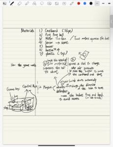
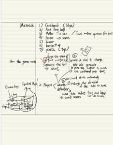
My understanding of interaction was also shown in the mechanics of the game.When a player successfully shooted the ball in the “hoop”,the distance infrared sensor would detect the subtle changes and passed the signal to the 8 segment LED to show scores.What’s more,since the score box and the shooting device was separated,the angle and direction of shooting was completed based on user’s choices.In other words,it provided users with freedom in their experiences.The whole project was made by cardboard because Melissa and I were familiar with using it and cardboard was convenient,versatile and user-friendly.This perfectly fit my criteria that the material should be handy and be subject to change according to our ideas so that we could make changes during the whole fabrication process.For shooting process, we used two motors(one spinned counter-clockwise and the other spinned clockwise) connected with two wheels to squeeze the ball out and this method ensured the shooting speed was fast enough.We also considered using fans but we gave up the idea because the shooting speed was slow and the subtle change of the wind’s direction made it hard to control the process of shooting. Here are our original ideas and a few sketches.
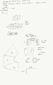
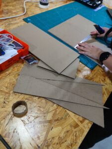
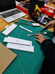
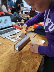
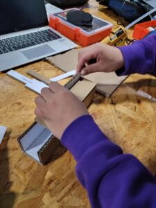
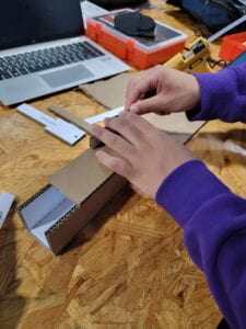
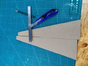
In the process of fabrication and production,I mainly in charge of coding,connecting the distance infrared sensor with the 8 segement LED and making the score box.At first,Melissa and I cut the cardboard into different sections:base,slope,side.In order to save space,we cut the rectangle in the middle and reconnected it to make the trapezoid shape of slope.
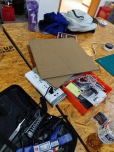
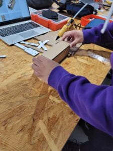
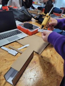
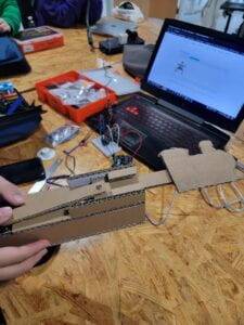
Later,we started to find appropriate motors and wheels.We found two motors that spinned at similar speeds.So I soldered the wires to the motors and used the hot melt glue gun to connect the center of the wheel to the motor.

However,after testing the speed of motors,we realized that it was nearly impossible to limit the whole project in a box and we decided to divide the project into two parts:the shooting device and the score box.Melissa would make the former and I would be in charge of the latter.

Next,I figured out how to test the distance infrared sensor with the help of Rudi and a learning assistant: the distance could be set by using a screwdriver and once the sensor detected something,the LED light would shine.Then I focused on how to connect the 8 segement LED.I viewed the website of DFRobot and follow the instructions.A few minutes later,it worked!
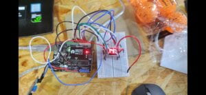
After that,the code became one of the biggest problem.Hence,I turn to the learning assistant for help.We discussed and worked out the logic of the detecting process together.The process was divided into four parts:the ball was faraway and score maintained original status;the ball was near and score maintained original status;the ball was near and score added one;the ball was faraway and score made no change. After several testing,we successfully avoid the problem of counting score twice.But a new problem occurs:everytime the score reached 9,it would suddenly changed back to 0. I checked the code and found out the problem was that the maximum of count was 9 but it should be 10 to ensure the existance of 9.Therefore, I revised and if count was equal to 10 then it would change back to 10.Here is the code.(The original code came from https://mc.dfrobot.com.cn/thread-2537-1-1.html)

int sensor = 10;
int tiltVal;
int prevTiltVal;
int count=0;
int distance;
int goal=0;
int number[10][8] = {
  { 0, 0, 0, 1, 0, 0, 0, 1 },  
  { 0, 1, 1, 1, 1, 1, 0, 1 },  
  { 0, 0, 1, 0, 0, 0, 1, 1 },  
  { 0, 0, 1, 0, 1, 0, 0, 1 },  
  { 0, 1, 0, 0, 1, 1, 0, 1 },  
  { 1, 0, 0, 0, 1, 0, 0, 1 },  
  { 1, 0, 0, 0, 0, 0, 0, 1 }, 
  { 0, 0, 1, 1, 1, 1, 0, 1 },  
  { 0, 0, 0, 0, 0, 0, 0, 1 },  
  { 0, 0, 0, 0, 1, 1, 0, 1 }   
};
void numberShow(int i) {  
  for (int pin = 2; pin <= 9; pin++) {
    digitalWrite(pin, number[i][pin – 2]);
  }
}

void setup() {
pinMode(sensor, INPUT);

  Serial.begin(9600);  
  for (int pin = 2; pin <= 9; pin++) {  
    pinMode(pin, OUTPUT);

    digitalWrite(pin, HIGH);
  }
}
void loop() {
 
  distance=digitalRead(sensor);
if (count>=0&&count<=9){
  if(distance==1&&goal==0){
    count=count;
  }
  if(distance==0&&goal==0){
    goal=1;
    count=count+1;
  }
  if(distance==0&&goal==1){
    count=count;
  }
  if(distance==1&&goal==1){
    goal=0;
  }
}else if(count==10){
  count=0;
}

numberShow(count);

Serial.print(“count:”);
Serial.println(count);

Serial.print(“goal:”);

Serial.println(goal);
Serial.print(“distance:”);

Serial.println(distance);  
  delay(62);
  }

On the user testing recitation,we could only display our prototype.

To my surprise,there were people who loved our ideas and gave us many useful suggestions:
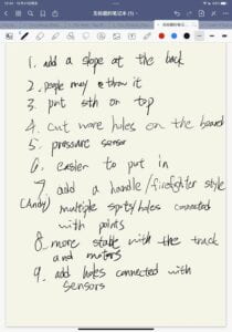
 

Based on the feedback,we made many changes to our prototype.For example,we added a small slope at the back before the ball touched the two motors,Melissa created a structure to make the shooting device more stable and easier for user to hold.(More information about the shooting device can be viewed on Melissa’s blog)

I started to build the score box.Since the slope didn’t work as our originial idea turned out to be unrealistic,I used the slope as the board on the back of the score box.I reused the cardboard with a rectangle to create a “hoop”.At first,I put the sensor on the back,but it seemed that the sensor couldn’t precisely detect the balls after several tests.

Hence,I used a tape to sticked it near the”hoop”,but beneath the upper board.

Then I designed a small box below to hold the circuits as well as balls.The one side of the box was open and I created a block the divide the circuits and balls.
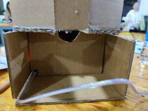
Hooooooray!

Our final task was to paint the device.Since Halloween was around the corner,we chose black and orange.
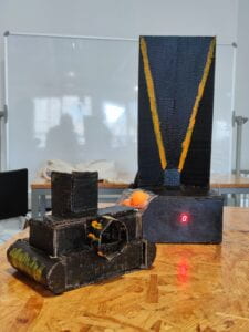
In conclusion,the overall goal of my project was to enrich my knowledge of interaction,including the understanding and the methods to realize it.The specific goal was to design a interesting device that can bring people happiness through interaction.In my opinion,our project basically matched my understanding of interaction because the two-way action is shown on the LED number and the angle,set during the user’s shooting process.The shooting action completely depended on the users themselves and they could have another try based on the previous shots.According to my understanding of interaction,the computer side(the Arduino circuits side) should do more things rather than only showing scores.This was the point that didn’t align with my definiton.

Therefore,there were things that needed improvements.For example,more handles or other features could be added to the shooting device since the users had to hold the device with one hand.Also,a ball picker could be designed below the score box so that there was no need to pick the balls by ourselves. 

In all,it was a wonderful experience because I got a deeper understanding of interaction,enhanced my skills in cardboards and Arduino even though I faced many obstacles.Most importantly,I learned a lesson from it:Only through practice can we change idea into reality.We might fail many times during the process to success,but we should never give up and we should keep a good mindset and strive.Also,it’s fine to find help from others since no one is born a genius. 

I regard interaction as a crucial factor in our daily lives because now we are living in an advanced and modern society and everyone is connected in some way. I do believe interaction can and should make life better.

Annex:
Recitation 4: Actuators & Mechanisms

Recitation day!

This time, Melissa and I would use cardboard to create a mechanism.

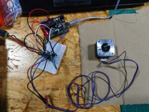
In order to save time and improve efficiency, I built the circuit while Melissa was cutting the cardboard.To be honest,the circuit was so complex that I was irresolute the first time I saw it.However,I decided to challenge myself .I managed to built the circuit with the examples of the diagram even though I revised several times on the cables connected to the four ground ports.Then I asked the learning assistant to check my circuit and it was correct.She even gave me a thumbs up!I was glad that I faced what I wasn’t good at.Later, I typed the code in the arduino and the motor spinned as expected.

After I finished building the circuit,I helped Melissa with cutting the cardboard.

After that,we used tht hot melt glue gun to stick the different parts of the cardboard.

Minutes later, the basic structure emerged and we placed the motor on the back of the device.It worked!

For the last step,I decided to cut the shape of a train because the process of the motor’s rotating was similar to the spinning process of the wheels on the trains.Here was how it looked.

The train is coming!Toot toot~

Additional questions

1.Daniel Palacios Giménez also used motors in his artifact “Waves” in 2006.Motors rotate an elastie rope to create complicated sounds and visual wave oscillations. The artifact creates the illusion of solid shapes for the viewers since the exposure blurs multiple rope positions.Compared with my work,I think his design is more complex and brings greater visual impact because the rope keeps moving and the visions are diverse.Hence,I think the usage of motors in his design really contributes to the artifact’s success.

2.

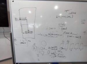
As the note demonstrates,I will use the motors to squeeze the ping pong ball so that the shooter can shoot the ball(the inspiration comes from the tennis ball serving machine)and this is much more feasible and more interesting than using an animation on a digital screen.