Senses—Dialogue in the dark
Jack(Jinyuan Xu)
Instructor:Rudi
CONCEPTION AND DESIGN:
The concept of my project was to design a mini-game that allowed users to experience the lives of visually-impaired people. In the game,the user needed to step on the corresponding pad after hearing the audio instructions in order to avoid the oncoming cars. There were three main inspirations or reasons that contributed to my design.
Ernest Edmonds argued in his article Art,Interaction and Engagement “There are three kinds of engagement: attracting,sustaining,relating“(Edmonds,12). He also classified interavtive art systems into four categories: Static, Dynamic-Passive, Dynamic-Interactive and Dynamic-Interactive(Varying). I regarded the last two categories as my ideal art systems for the final project because” the human ‘viewer’ has an active role in influencing the changes in the art object…with the addition of a modifying agent that changes the original specification of the art object”(Edmonds,3). What’s more,this illuminating idea affected my definition of interaction. In my opinion, interaction means acting with each other ,whether it is the acting between people,computers or between people and computers. And there are no restrictions on how these actions can be presented. More importantly,this is a two-way acting,which means both sides have to respond to the other’s reactions. Besides,interaction should be something that is playable or subjected to change.
The second inspiration was from a VR game that I researched called Beat Saber. The game used two devices that resembled swords to chop the cubes while following the beat and music. In this case, the VR equipment displayed several cubes as “hitting” instructions to the user. The user then took steps in accordance with the directions. After “hitting” the cubes, new animations would display on the screens to notify the player that he had successfully struck the cubes in the game.Through this circulation as well as two-way acting,the user could interact with the VR device and achieve great fun. Also, it inspired me to use audios in my project to promote innovative ideas since the convention tended to focus on visuals. To be more specific, I used audio instructions or sounds as the output of the computer side. In the game, the user could only hear the sound of a car driving by from the left or right channel. If the sound was from the right channel, he or she had to move to the left channel to show that he or she had dodged the car.
The third inspiration was from a walking experience on the pavement in Shanghai. Many of China’s blind paths had issues such as broken or uneven surfaces, bicycles and electric cars occupying the blind paths, and so on. Based on these observations, I believed it was time for us to raise awareness of this issue and to show concern for the visually-impaired people. Therefore, the user had to close his or her eyes and he or she could only rely on hearing and tactile sensation. Then the user had to stand on or move between the special pads according to what they heard. What’s more, I also added tutorial part in the project to let the user get used to the black surroundings as well as the feeling on pads.
Here was my draft and the original ideas:
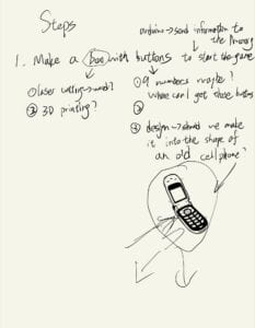
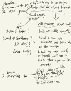
However, after the conversation with Rudi,I realized that the design of old cell phone was a bit off the pad game so I used a bicycle trumpet as a substitution.
Here was the original design of what would the whole process be like(some parts were removed after practice):
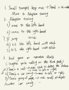
For the user testing session, I only showed the tutorial part of my project. Still, I received some useful suggestions.
The first feedback was that the user were sometimes afraid to step on the pads because they might fall off so that they couldn’t help opening his or her eyes to see the ground. Therefore, I chose to use a patch to cover the user’s eyes and I found it helpful.
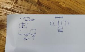
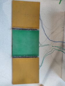
The second problem was that the user might get lost about on which pad they stood since the three pads felt exactly the same. The tester discussed with me and we figured out two solutions: one was to add baffle between each two pads and the other was to place the pads separately and to regard the floor as intervals. These two methods were both good for my project, but I worried that the latter would cause user to slip. After comparison, I chose to add baffle between each two pads, which not only enabled the user to have a clue about his or her position and next move but also reduced safety hazards.
The third problem was that the user might not know where to stand at the very beginning.Hence, laying a paper that wrote “Start Here” with a footprint could help solving this problem.
FABRICATION AND PRODUCTION:
The first thing was to produce three pads. Luckily, I found some ideal pads in the Fabrication Lab.
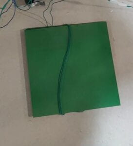
Each pad consisted of two boards. In the space between two boards, the four corners were affixed with EVA foams and the middle part was similar to the DIY Paddle button that I had made in the Recitation 1.(You can check it here:https://wp.nyu.edu/jinyuanxu/2022/09/20/recitation-1electronics-soldering/) Once the user stepped on the pad and no matter where he or she was, the button would be pressed. This design was sensitive enough to detect the state of pressing and to send signals to the computer.
Next, I built a circuit with three pads, two vibration sensors and one sound sensor. The sound sensor was used to detect the sound of the bicycle trumpet, thus adding a sense of humor in the project. Besides, the sound sensor was easy to use and can directly convert volume into data. The reason why I use vibration sensors was that they were more sensitive than pressure sensors to detect the movements of walking stick. However, I also took feasibility into consideration so that I deleted vibration sensors and walking stick later.
Here was the testing part for the circuit:
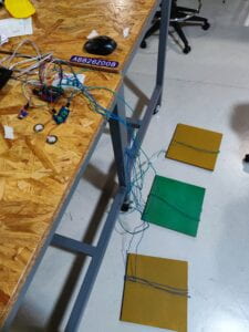
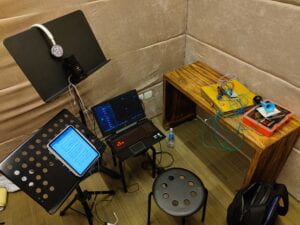
Then I recorded all the audio instructions such as”move to the left pad” and the background setting by myself because I would like to let the user immerse in the world of visually-impaired people. Otherwise, reading out the instructions when presenting could be unclear or drag user out of the narrative. Here was the place for recording:
The most difficult part for me was coding. Though it was all about audios and sounds,there was still a lot to study, for example, the usage of pan() and isPlaying(). Problems such as overlapping sounds and incomplete playback also occured from time to time. Hence, I searched the internet for code instructional videos and websites. I also turned to professors and learning assistants for help. In the end, I made it and achieved my ideal results. The codes had different versions after countless debugging and I will attach the final version in the annex part.
After the user testing part, I used cardboard and hot melt glue gun to build baffle between each two pads. At first, I only put one thin cardboard as a baffle. However,it turned out that it was so fragile that it could be easily destroyed by user’s feet. Therefore, I cut the height in half and glued three strips of cardboard together to make it more stable and solid.
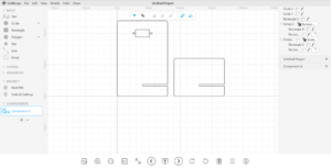
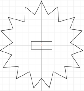
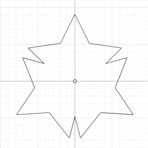
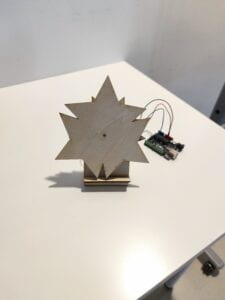
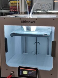
The last part was about decoration. I referenced the cable reel organizer by READY4RENDER to place the wires in a more orderly way.(https://cults3d.com/en/3d-model/tool/cable-reel-organizer) Here was the 3D printing process:
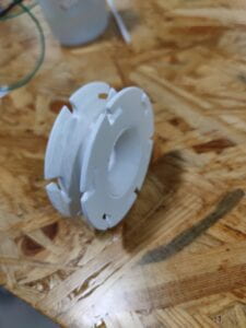
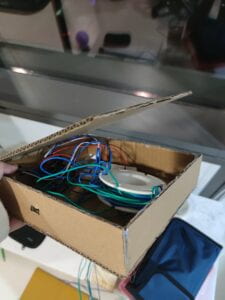
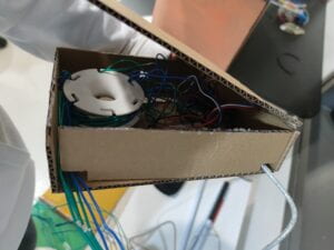
At last, I put the organizer and Arduino in a small cardboard box that I made. Viewing from outside, the only thing exposed was the sound sensor. In this way, the whole project wouldn’t be affected by those complicated wires.
This link was the video of final presentation(the complete user experience) :
https://drive.google.com/file/d/1UcGbnhNT1e9q9AilpUhgXTP2uo08xVNL/view?usp=sharing
CONCLUSIONS:
The goal of my project was to allow people to experience the daily lives of the visually-impaired people, thus drawing attention to the social issue of unsafe blind paths as well as showing concern for them. From my point of view, my project achieved its stated goals because the user had to move between the pads very carefully and this was only a small part of the visually-impaire people’s lives. Hence, user could deeply feel the difficulty of their lives. Another point was that the user did focus on audios or voices to interact. After hearing the instructions, the user moved accordingly. Then these moves on the pads or the squeezing sounds were translated into signals that the computer could recognize. This continuous cycle of communication was in tune with my definition of interaction: acting with each other ,whether it is the acting between people,computers or between people and computers. And there are no restrictions on how these actions can be presented. More importantly,this is a two-way acting,which means both sides have to respond to the other’s reactions. Besides,interaction should be something that is playable or subjected to change. If I had more time, I would use this project as a prototype and add more elements to it. For example, the sounds of crowds talking, bicycle bells and bus passing could be included. The walking stick and the two vibration sensors could also be a new direction to explore: the user needed to keep tapping the two sensors left and right to sense the surrounding environment, just like the visually-impaired people did in reality.
From my practice and experiences, I learned a lot. The first thing was that coming up with ideas and making them happen were both important. The former was more like the result of free imagination, while the latter was based on the former and the practice of continuous adjustments. What’s more, coding needed much patience. When debugging, sometimes clarifying the overall logic and structure first and then focusing on the details was a better way. Last but not least, as long as you had the courage to persevere, you would always have something to gain and this could be applied to any learning process.
At the end of my report, I believed that a good artifact should not only be playable, but also have a certain social significance or a value of further thinking. Although the forms could be varied, this connotation was throughout every good artifact. When the content of the artifact was deepened, we came to realize that all interaction matters.
ANNEX:
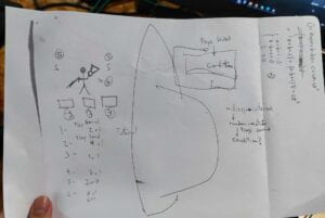
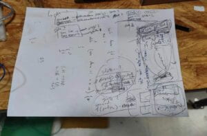
Several sketches:
Arduino code:
#include “SerialRecord.h”
#define sensorPin A0
//#define sensorPin2 A1
//#define sensorPin3 A2
const int buttonPin = 2; // the number of the pushbutton pin
const int button2 = 3;
const int button3 = 4;
// int sensorPin2 = A1;
// int sensorPin3 = A2;
SerialRecord writer(4);
int buttonState = 0; // variable for reading the pushbutton status
int buttonState2 = 0;
int buttonState3 = 0;
int sensorValue = 450;
// int sensorValue2=0;
// int sensorValue3=0;
void setup() {
Serial.begin(9600);
// initialize the LED pin as an output:
pinMode(sensorPin, INPUT);
// pinMode(sensorPin2, INPUT_PULLUP);
// pinMode(sensorPin3, INPUT_PULLUP);
// initialize the pushbutton pin as an input:
pinMode(buttonPin, INPUT_PULLUP);
pinMode(button2, INPUT_PULLUP);
pinMode(button3, INPUT_PULLUP);
}
void loop() {
// read the state of the pushbutton value:
buttonState = digitalRead(buttonPin);
writer[0] = buttonState;
buttonState2 = digitalRead(button2);
writer[1] = buttonState2;
buttonState3 = digitalRead(button3);
writer[2] = buttonState3;
sensorValue = analogRead(sensorPin);
writer[3] = sensorValue;
writer.send();
delay(20);
}
Processing code:
import processing.sound.*;
import processing.serial.*;
import osteele.processing.SerialRecord.*;

Serial serialPort;
SerialRecord serialRecord;
SoundFile sound1, sound2, sound3, sound4, sound5, sound6, sound7, sound8, sound9, sound10, sound11, sound12;

int state=0;
int state2=0;
long prevTime;
float starttime;
boolean[] get = new boolean[6];
int panning=1;
int count = 0;
int preval0=0;
int preval1=0;
int preval2=0;
int[] played=new int[6];
int[] played2=new int[6];
int played3 = 0;
void setup() {
  //delay(1000);
  size(758, 480);
  // String serialPortName = SerialUtils.findArduinoPort();
  serialPort = new Serial(this, "COM17", 9600);
  serialRecord = new SerialRecord(this, serialPort, 4);
  sound1 = new SoundFile(this, "gameinstruction2.wav");
  sound2 = new SoundFile(this, "middlepad.wav");
  sound3=new SoundFile(this, "leftpad.wav");
  sound4=new SoundFile(this, "rightpad.wav");
  sound5=new SoundFile(this, "hornstart.wav");
  sound6=new SoundFile(this, "gameinstruction.wav");
  sound7=new SoundFile(this, "horninstruction.wav");
  sound8=new SoundFile(this, "carinstruction.wav");
  sound9=new SoundFile(this, "the end.wav");
  sound10=new SoundFile(this, "wrong.wav");
  //println("Number of audio frames: " + sound10.frames());      //185337
  sound10.loop();
  sound10.pause();
  sound11=new SoundFile(this, "car.wav");
  //sound11.loop();
  sound12=new SoundFile(this, "correct.wav");
  sound1.play();
  state=0;

}
void draw() {
  //get = false;
  background(0);

  serialRecord.read();
  int val0 = serialRecord.values[0];
  int val1 = serialRecord.values[1];
  int val2 = serialRecord.values[2];
  int val3 = serialRecord.values[3];


  if (state == 0&&sound1.isPlaying()==false&&millis()>15000) {
    //INTERVAL=8000;
    //println(state2);
    if (val0==1&&val1==1&&val2==1&&state2==0) {
      sound2.play();
      state2=1;
    }
    if ((val0==1)&&(val1==0)&&(val2==1)&&(state2==1)) {
      sound3.play();
      state2=2;
    }
    if ((val0==0)&&(val1==1)&&(val2==1)&&(state2==2)) {
      sound4.play();
      state2=3;
    }
    if ((val0==1)&&(val1==1)&&(val2==0)&&(state2==3)) {
      sound5.play();
      state2=4;
      //INTERVAL=6000;
      //if(get==true){
      // starttime=millis();
      // get=false;
      //}
      //if((starttime-millis())>5000){
      //sound10.play();
      //state2=4;
      //}
    }
    if ((state2==4)&&(val3>477)) {
      sound8.play();
      starttime=millis();
      while (sound8.isPlaying()==true) {
        //serialRecord.read();
        if ((millis()-starttime)>8000) {
          sound8.stop();
          println("Moving to state 1");
          //state=1;
          state = floor (random(1, 3));
        }
      }
    }
  }
  if ((count<5) && (sound8.isPlaying()==false) && (sound11.isPlaying()==false) && (sound12.isPlaying()==false)) {
    println(count);
    if (state==1) {
      if (played[count]==0) {
        played3=1;
        panning=1;
        sound11.play();
        sound11.pan(panning);

        played[count]=1;
        //println("1");


      }
      //if(sound11.isPlaying()
      if ( !sound11.isPlaying()) {
        //serialRecord.read();
        //println("2");
        if (val0==0 && val1==1 && val2==1&&played2[count]==0) {
          sound12.play();//yes,you stand on the correct pad
          println("yeah");
          get[count]=true;
          played2[count]=1;
          count++;
          state = floor (random(1, 3));
          played3=0;
        }else {
        if(played2[count]==0){
        sound10.play();

        state = floor (random(1, 3));
        played2[count]=1;
        count++;
        played3=0;
        }
        }
      }
    }

    if (state==2) {
      if (played[count]==0) {
        panning=-1;
        sound11.play();
        sound11.pan(panning);
        played[count]=1;

      }

      if ( !sound11.isPlaying()) {
        //serialRecord.read();
        if (val0==1 && val1==1 && val2==0&&played2[count]==0) {
          sound12.play();//yes,you stand on the correct pad
          //println("yeah");
          get[count]=true;
          played2[count]=1;
          count++;
          state = floor (random(1, 3));
        }else{
        if(played2[count]==0){
        sound10.play();

        state = floor (random(1, 3));
        played2[count]=1;
        count++;
        }
        }
      }
    }

  }
  if(count==5  && (sound10.isPlaying()==false)&& (sound11.isPlaying()==false) && (sound12.isPlaying()==false)){
  sound9.play();
  count++;
  }
}
Work Cited:
1.Edmonds E. Art, Interaction and Engagement. 2011 15th International Conference on Information Visualisation, Information Visualisation (IV), 2011 15th International Conference on. July 2011:451-456. doi:10.1109/IV.2011.73
2.The cable reel organizer
https://cults3d.com/en/3d-model/tool/cable-reel-organizer
