- Starting the lab by locating a 100-ohm resistor. (figure 1)
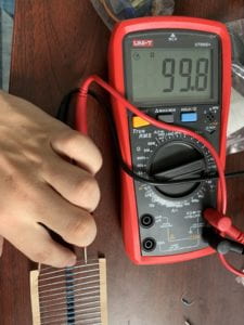 figure 1
 - Realizing there will be a lot of components in this lab, so I connected the breadboard utilizing the whole board instead of half of it like in the previous labs. (figure 2)
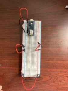 figure 2
 - Adding the first force-sensing resistor. (figure 3)
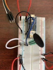 figure 3
 - Adding the second force-sensing resistor in serial with the first one. (figure 4)
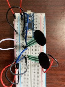 figure 4
 - Connecting the speaker to port 8. (figure 5)
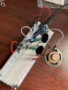 figure 5
 - With the following code, I check the range of the sensors output.
void setup() {
Serial.begin(9600);
}void loop() {
int analogValue = analogRead(A0);
Serial.println(analogValue);
} - The range of the sensor output is from 0 – 1023 according to the serial monitor. (figure 6, figure 7, figure 8)
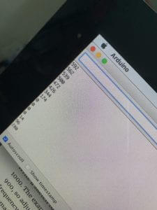 figure 6
 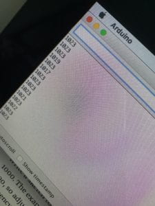 figure 7
  figure 8
 - Therefore, for the first exercise, to make the speaker sound with one tone, the code looks like this. Video 1 shows it at work.
void setup() {
// put your setup code here, to run once:}void loop() {
int sensorReading = analogRead(A0);
float frequency = map(sensorReading, 0, 1023, 100, 1000);
tone(8, frequency, 10);
}video 1
- The breadboard remains the same for the second exercise — A more complex example. I used nested for loops so it plays five times, giving me enough time to capture it on video. Note that after clicking the adding new tab, the prompt for file name shows up at the bottom of the Arduino App. That’s where I can copy and paste the array of variables of different notes. Video 2 shows the final result of this exercise.
# include “pitches.h”
int melody[] = {NOTE_C4, NOTE_G3, NOTE_G3, NOTE_GS3, NOTE_G3, 0, NOTE_B3, NOTE_C4 };
int noteDurations[] = {4, 8, 8, 4, 4, 4, 4, 4};
void setup() {
for (int i = 0; i < 5; i++){
for (int thisNote = 0; thisNote < 8; thisNote++) {
int noteDuration = 1000 / noteDurations [thisNote];
tone(8, melody[thisNote], noteDuration);
delay(noteDuration +30);
}
}
}void loop() {
// put your main code here, to run repeatedly:}
video 2 - For the next exercise, I changed the breadboard to have two sensors in parallel. The initial code looks like this with the threshold being 10. I only have two sensors, so I can only have two notes and thisSensor needs to be less than 2: they are at A0 and A1.
#include “pitche.h”const int threshold = 10;
const int speakerPin = 8;
const int noteDuration = 20;int notes[] = {NOTE_A4, NOTE_B4};
void setup() {
// put your setup code here, to run once:}
void loop() {
// put your main code here, to run repeatedly:
for (int thisSensor = 0; thisSensor < 2; thisSensor++){
int sensorReading = analogRead(thisSensor);
if (sensorReading > threshold) {
tone(speakerPin, notes[thisSensor], noteDuration);
}
}
} - It works. But with a constant noise. (video 3)
video 3 - Then I change the threshold value from 10 to 50. The noise is gone. (video 4)
video 4
Interface Lab
Documenting Lab: Analog In with an Arduino
- Starting the board like figure 1.
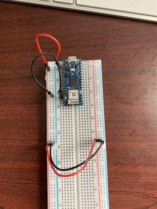 figure 1
 - DANGER. Smelled burn from the potentiometer with layout in figure 2. Was trying to save space by placing the resistor right next to the board… (what was I thinking) Don’t do this. Also the port lost connection with the board once the upload was completed. I thought there might be a conflict between my USB keyboard and the Arduino so I even unplugged my usb keyboard. But I guess the real reason may be that I shorted the port for USB connection or the entire board.
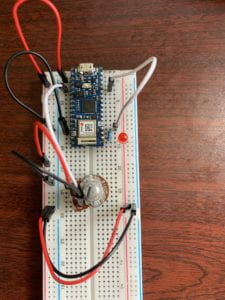 figure 2
 - Moving the resistor and LED downwards. (figure 3)
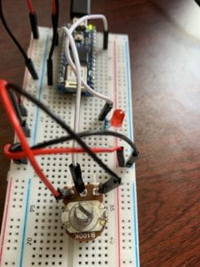 figure 3
 - Coding went smoothly. Here is the final code.
const int ledPin = 9;
int analogValue = 0;
int brightness = 0;
void setup() {
// put your setup code here, to run once:
Serial.begin(9600);
pinMode(ledPin, OUTPUT);
}void loop() {
// put your main code here, to run repeatedly:
analogValue = analogRead(A0);
brightness = analogValue / 4;
analogWrite(ledPin, brightness);
Serial.println(brightness);
} - Here’s the final result. (figure 4 & figure 5) note the position of the turn button.
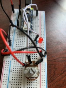 figure 4
 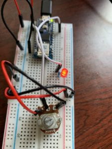 figure 5
Documenting Lab: Digital Input and Output with an Arduino
- This is what I’m working with. Arduino Nano 33 IoT and a breadboard from Taobao. Note there is a gap in the middle of the breadboard. It will cause my major confusion later in the process. (figure 1)
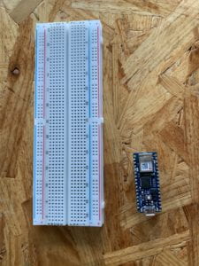 figure 1
2. It took some hard push to put the pins in. (figure 2) It was difficult to identify the pins from the front. So I unmounted it and took pictures of the flip side before mounting it back on the board. (figure 3) Then I can compare the front and back sides to locate the correct pins. Note the ground is marked with a white square on both sides.
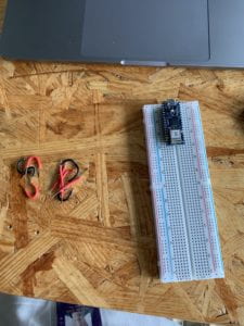 figure 2
 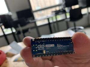 figure 3
3. Figure 4 shows the 3.3V output and ground connection from the Arduino to the breadboard. Note the connection between red and blue of the left column and of the right column at the bottom. Because of the gap in the middle (where 30 mark is), this only connects the left and right column of the lower half of the breadboard. The upper left half (mark 0, 5, 15, 20, 25, 30) is not connected.
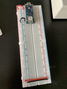 figure 4
4. Then I confirm the color code on the resistor with this document. Figure 5 shows a 10-kilohm resistor.
1 (1st band brown) 0(2nd band black) 0(3rd band black) *100 (4th band red) + tolerance (5th band)
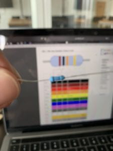 figure 5
5. Then I located two 200-ohm resistors. I confirmed them by using a multimeter. (figure 6)
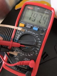 figure 6
6. Obviously this layout is not going to work because the middle of the breadboard is not connected! (figure 7) The correct connection is shown in figure 8. I also changed into using the jump wires. Much easier than cutting and stripping the wires, but at least I got practice.
Note the 30 on the left is now connected to the 30 on the right with the red and black jump wire at the bottom. I’m only using the upper half of the breadboard.
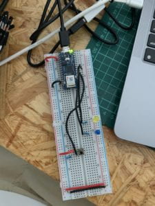 figure 7
 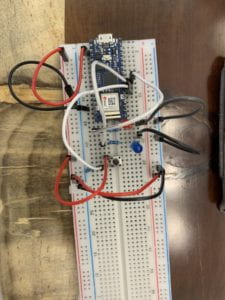 figure 8
7. Running the Arduino App and programming did not give me too many surprises. I used the following code to help me rule out the possibilities when the lights are not turning on during figure 7.
void setup() {
pinMode(4, OUTPUT);
}
void loop() {
digitalWrite(4, HIGH);
}
8. Here is the final result and the final code. (figure 9 & figure 10)
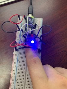 figure 9
 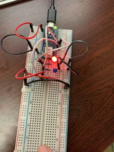 figure 10
void setup() {
// put your setup code here, to run once:
pinMode(2, INPUT);
pinMode(3, OUTPUT);
pinMode(4, OUTPUT);
}
void loop() {
// put your main code here, to run repeatedly:
if (digitalRead(2) == HIGH) {
digitalWrite(3, HIGH);
digitalWrite(4, LOW);
}
else {
digitalWrite(3, LOW);
digitalWrite(4, HIGH);
}
}
Discovering Sensors
Assignment:
Take a walk around your neighborhood, or a different one, or imagine a walk you’ve done routinely. Take a count of every interaction with a sensor you see or experience. Blog your findings:
- Identify the sensors and how they sense (or do not sense) you / someone else?
- Does the sensor make itself known to you? If so, how?
- How do you know if the sensor has sensed?
- Is there more than one stage of interaction or multiple interactions?
Feel free to take pictures or video as appropriate, of the most interesting ones. Some sensors might include: pushbuttons, motion sensors, floor mats, cameras, smart devices
In the morning, I get off my bed, take a walk in the garden, and use the water well pump to water my plants.
Light and motion sensor (figure 1): when there is no light sensed AND when there is movement sensed, it turns on the night light. I know it has sensed when the light is on. The sensor does not make itself known to me.
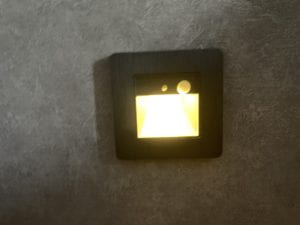 figure 1
Solar lights (figure 2)
When there is sunlight sensed, the LED light is switched off. Meanwhile solar energy is transformed into electricity to be stored in the battery. When there is no sunlight sensed, the LED light turns on by the battery. I know it has sensed when the light is off. The sensor does not make itself known to me other than from the user manual.
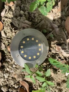 figure 2
Solar pump (video 1)
when it detects sunlight, it switches to run through solar energy. Otherwise, it switches to use the battery. I cannot tell if it has sensed. The sensor does not make itself known to me other than from the user manual.
video 1
Vacuum pump with a pressure sensor (figure 3)
When the pressure in the pipe reaches certain level, it pauses the pump motor. When the pressure drops below certain level, it engages the motor. I know this sensor has sensed by observing the pressure of my water and by hearing the noise of the motor. The sensor does not make itself known to me. It’s hidden in the pump.
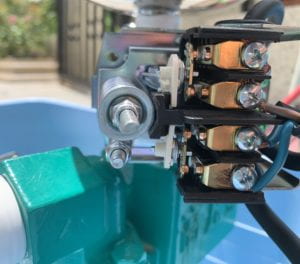
figure 3
For all these sensors, there is only one stage of interaction.