- This is what I’m working with. Arduino Nano 33 IoT and a breadboard from Taobao. Note there is a gap in the middle of the breadboard. It will cause my major confusion later in the process. (figure 1)
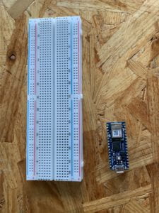 figure 1
2. It took some hard push to put the pins in. (figure 2) It was difficult to identify the pins from the front. So I unmounted it and took pictures of the flip side before mounting it back on the board. (figure 3) Then I can compare the front and back sides to locate the correct pins. Note the ground is marked with a white square on both sides.
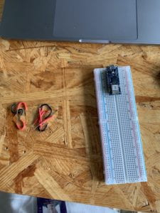 figure 2
 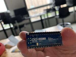 figure 3
3. Figure 4 shows the 3.3V output and ground connection from the Arduino to the breadboard. Note the connection between red and blue of the left column and of the right column at the bottom. Because of the gap in the middle (where 30 mark is), this only connects the left and right column of the lower half of the breadboard. The upper left half (mark 0, 5, 15, 20, 25, 30) is not connected.
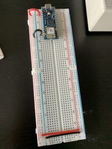 figure 4
4. Then I confirm the color code on the resistor with this document. Figure 5 shows a 10-kilohm resistor.
1 (1st band brown) 0(2nd band black) 0(3rd band black) *100 (4th band red) + tolerance (5th band)
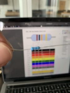 figure 5
5. Then I located two 200-ohm resistors. I confirmed them by using a multimeter. (figure 6)
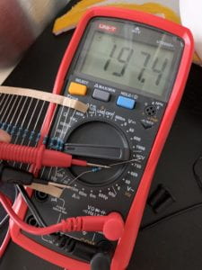 figure 6
6. Obviously this layout is not going to work because the middle of the breadboard is not connected! (figure 7) The correct connection is shown in figure 8. I also changed into using the jump wires. Much easier than cutting and stripping the wires, but at least I got practice.
Note the 30 on the left is now connected to the 30 on the right with the red and black jump wire at the bottom. I’m only using the upper half of the breadboard.
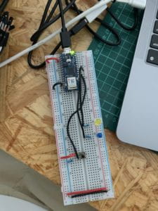 figure 7
 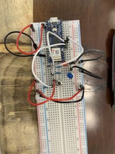 figure 8
7. Running the Arduino App and programming did not give me too many surprises. I used the following code to help me rule out the possibilities when the lights are not turning on during figure 7.
void setup() {
pinMode(4, OUTPUT);
}
void loop() {
digitalWrite(4, HIGH);
}
8. Here is the final result and the final code. (figure 9 & figure 10)
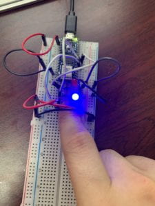 figure 9
 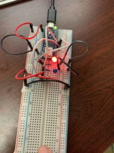 figure 10
void setup() {
// put your setup code here, to run once:
pinMode(2, INPUT);
pinMode(3, OUTPUT);
pinMode(4, OUTPUT);
}
void loop() {
// put your main code here, to run repeatedly:
if (digitalRead(2) == HIGH) {
digitalWrite(3, HIGH);
digitalWrite(4, LOW);
}
else {
digitalWrite(3, LOW);
digitalWrite(4, HIGH);
}
}
Leave a Reply