Task: Create a kinetic sculpture using digital fabrication tools.
Step 1: design
I paired up with my friend Tina to do this recitation since we work very well together!
First off we both opened cuttle.xyz (which is a 2D vector software optimized for laser cutting) and divided the work. Tina chose to be Student B and I chose to be Student A.
Step 1.1: The first task we needed to complete was building the stand for our structure.
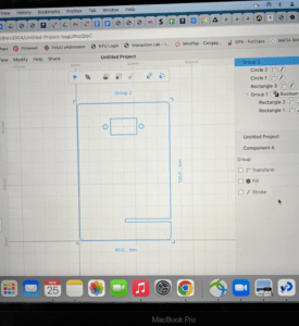
- For the Student A instructions, first I switched my cuttle settings to millimeters and created a new document activating grid snapping.
- I drew a rectangle that was 80mm wide and 120mm tall and rounded the corners to a 3mm radius.
- Then I created another triangle that was 40 mm wide and 2.8 mm placing it at 17.5 mm on the Y axis.
- Using boolean difference I merged the two rectangles together to create one shape. Next, I used Tina’s measurements of the servo motor and plotted a triangle at at Y -100 mm centered within the triangle.
- Lastly I used the next set of measurements Tina took of the servo to plot two circles on either side of the rectangle for the screw holes and grouped all the shapes together.
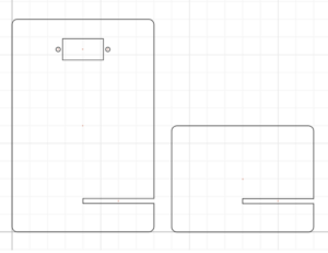
This is the final product of the two pieces together! Student A (my part) is on the left and Student B (Tina’s part) is on the right.
Step 1.2: creating fun design
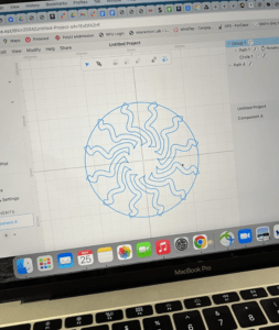
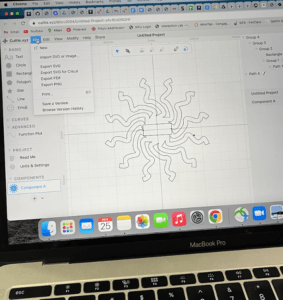
First I created a circular pattern of 120 mm in diameter.
I create a shape using the pen tool and put it on rotational repeat, outlining the stroke. My part of the project included the static with a square cut-out (32.5 x 12.5 mm) for the servo to go through and Tina’s included the circle diameter 4.5 mm to attach to the servo and activate the servo sweep function on Arduino.


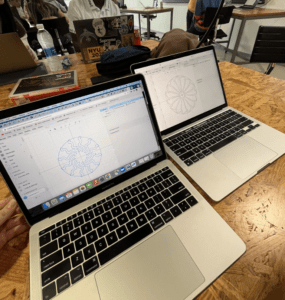
The design on the left is Tina’s design and the design on the right is my design. Because of the format of the download its a little difficult to see the designs we created but they will be more visible later.


Step 2: Lazer Cutting
Tina and I where the first people to finish in our recitation section so we went directly to the fabrication lab in 823 where Andy was waiting for us to lazer cut out designs. Turns out that there was a small mistake initially with our designs where one part of the design would be cut off if it were cut so Andy helped us fix it on Adobe Illustrator and then we got started with printing.
During this time Silvia kindly gave us a tour of the fabrication lab 🙂
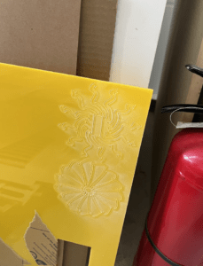
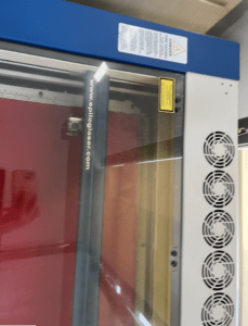
Then we came back to see our print but something had gone wrong with the cut where the design didn’t get cut all the way through so we needed to lazer cut again.
Step 3: Building the structure 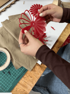
We connected the servo wires to our Arduino with the File > examples > Servo > Sweep example and then attached all the pieces together. At first we had an issue because the 4.5mm size cut out on Tina’s piece turned out to be too small so we ended up using tape to put the pieces together.
Code:
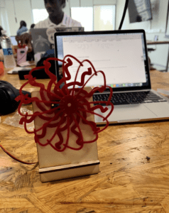
Final Product
Reflection
The result of our project was really cool and I enjoyed making it with Tina. Overall, I think that there are so many things we can do with this tech to make something cool and I definitely look forward to utilizing the skills I learned in this recitation in the future.
Leave a Reply