Introduction
It is common for people to bring a box of candy or chewing gums and share them with their friends. However, what if this box turned out to be a prank box with screaming sound and lights rushing out, what would the story be like?
In our project, Tom, Barry and I attempt to build a prank box. We are going to explore the function of the 555 timer IC and its applications in the production of toys with sound and light. We are going to learn about its basic internal architecture, its different operating modes as well as utilizing other components including speakers, LEDs, potentiometers, and so on. In the process of making the prank box, a comprehensive understanding of each component and a skillful usage of breadboard or soldering tools are prerequisites. Furthermore, we also anticipate potential challenges such as finding the proper value of the potentiometers, combining different circuits together, etc. Thus, we also anticipate an educational process.
Lastly, excitement always comes from the experiences that are out of expectations–so does our prank box–you’ll never know what will come out before you open it!
Material
| 1 | Iron box | x1 |
| 2 | Battery 1.5V | x4 |
| 3 | Perfboard 4cm*6cm 2.54mm | x2 |
| 4 | Rheostat 1kΩ | x1 |
| 5 | Rheostat 20kΩ | x1 |
| 6 | Resistance 1kΩ | x2 |
| 7 | Resistance 4.7kΩ | x1 |
| 8 | Resistance 470Ω | x1 |
| 9 | Speaker 8Ω | x1 |
| 10 | Capacitor 0.01μF | x3 |
| 11 | Capacitor 4.7μF | x1 |
| 12 | NE555 IC | x2 |
| 13 | CD4017 IC | x1 |
| 14 | LED lights (different colors) | x8 |
| 15 | Photoresistance | x1 |
| 16 | Cables | – |
| 17 | Solder | – |
Tools
| 1 | Multimeter |
| 2 | Soldering Iron |
| 3 | Breadboard |
| 4 | Glue gun |
| 5 | Wire Clipper |
Research – CD4017 IC

After determined our topic, we decided to use the 4017 IC as our key component for the chaser – a combination of nights shining one after another.
Introduction
CD4017 is a decimalism IC counter which can give 10 outputs under certain circumstances. A CD4017 IC has 16 pins, 10 of which are outputs, their orders are as follows:
| Output | 0 | 1 | 2 | 3 | 4 | 5 | 6 | 7 | 8 | 9 |
| Pin | 3 | 2 | 4 | 7 | 10 | 1 | 5 | 6 | 9 | 11 |
And for other pins, their functions are also followed:
| Pin | Name | Effect |
| 8 | GND | Groud. Connect to a low voltage. |
| 12 | CO | Carry-out. When the counter has completed half a period, the output of this pin changes twice. Actually, when the counter output is between 0~4 (see above), the output of this pin is 0, when the counter output is between 5~9, the output of this pin is 1. |
| 13 | EN/INH | Disable. When the input is high level, the counter stops. This input pin, together with pin 14, controls the counter. |
| 14 | CLK/CP | Clock. This input pin, together with pin 13, controls the counter. |
| 15 | CR/RST | Reset. When the input is high level, the counter output returns to 0 (pin 3). |
| 16 | VDD | Power supply. 3V ~ 15V is allowed. |
Regarding Pin CP, EN, and RST, the counter output is as below:
|
Input
|
Output
|
|||
|
CP
|
EN
|
CR
|
Q0~Q9
|
CO
|
|
×
|
×
|
1
|
Q0=1 (Reset) |
When the counter output is between 0~4 (see above), the output of this pin is 0, when the counter output is between 5~9, the output of this pin is 1.
|
|
↑
|
0
|
0
|
Count
|
|
|
1
|
↓
|
0
|
||
|
×
|
1
|
0
|
Stay on, stop counting
|
|
|
0
|
×
|
0
|
Stay on | |
|
↓
|
×
|
0
|
||
|
×
|
↑
|
0
|
||
Note: “×” means an arbitrary value, “↑” means rising edge, “↓” means falling edge, “1” means high voltage, “0” means low voltage.
The Use of CD4017 in our Project
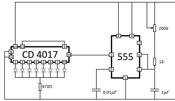
Based on the understanding of CD4017 IC, we designed the following circuit:
*See the completed circuit picture below.
As shown in the picture above. For output, we connect 8 LEDs with pin 1, 2, 3, 4, 5, 6, 7, 10. Since the output has 10 pins while we do not want the 8 LEDs to be all off at anytime, we connect pin 9 with pin 15 – when it comes to the 9th output, we deliver high voltage to the RST pin. In that case, the counter would return to its start. We also connect pin 13 (EN/INH) to the ground and pin 14 (CLK/CP) to pin 3 (OUT) of the NE555 timer. Thus, every time when OUT pin of NE555 timer delivers a rising edge signal to pin 14 of CD4017, the counter increases by 1 and the next LED light is turned on. After the 8th LED lights, the reset pin is activated, the counter returns 0 and the first LED light is turned on again.
Procedure
Step 1: Design the circuit
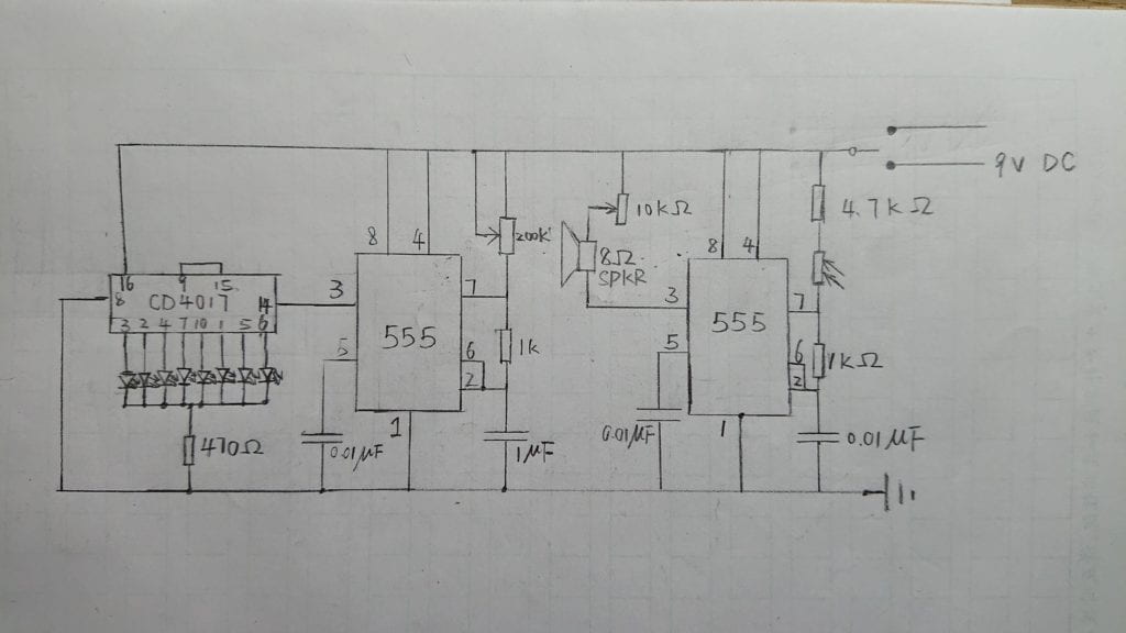
We firstly designed the circuit according to the NE555 handbook and CD4017 handbook. below is a picture of Barry’s sketch and my corrected version. I also ran the circuit on the online simulator to test if it works.

Step 2: Connect the Breadboard
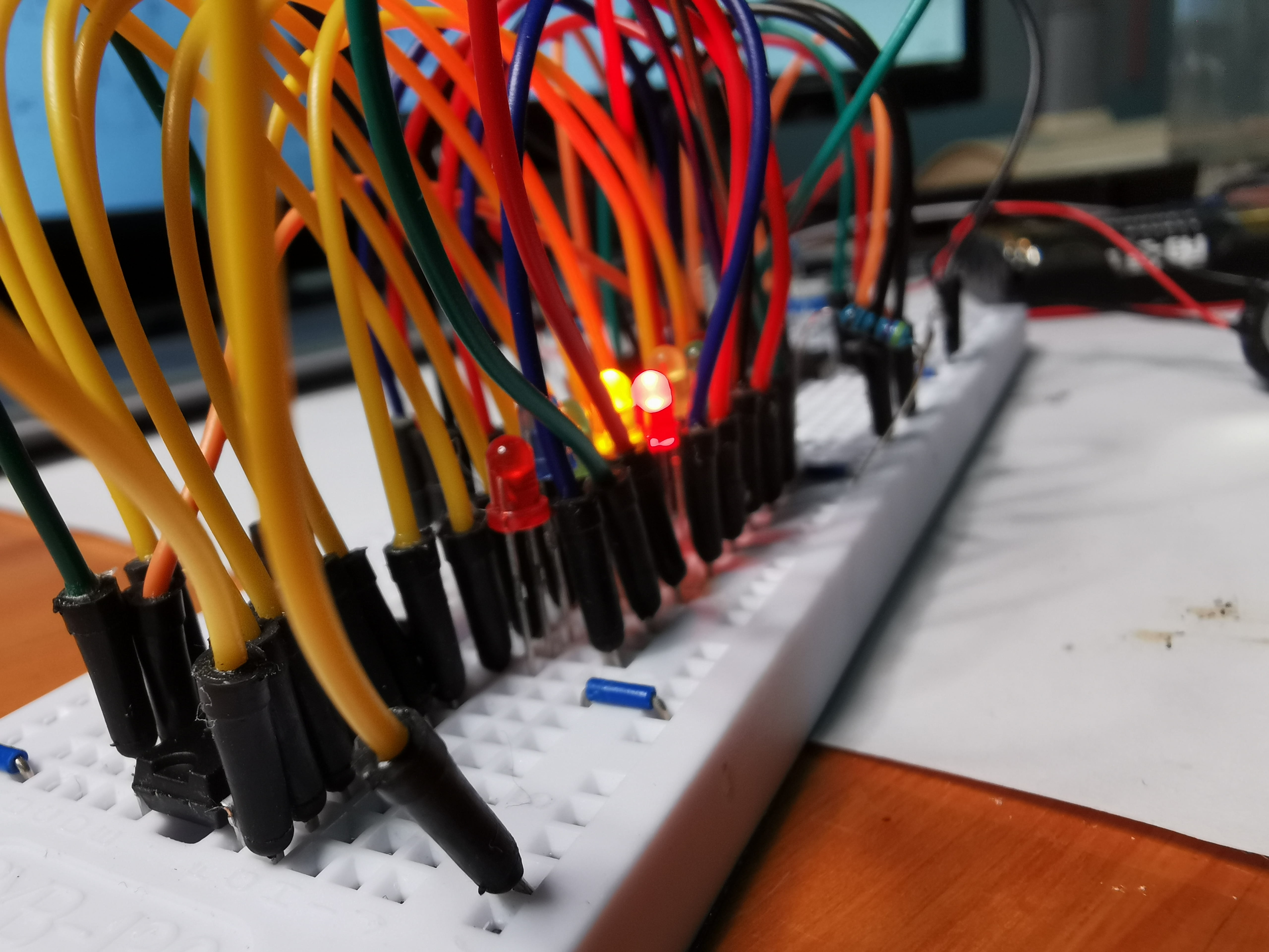
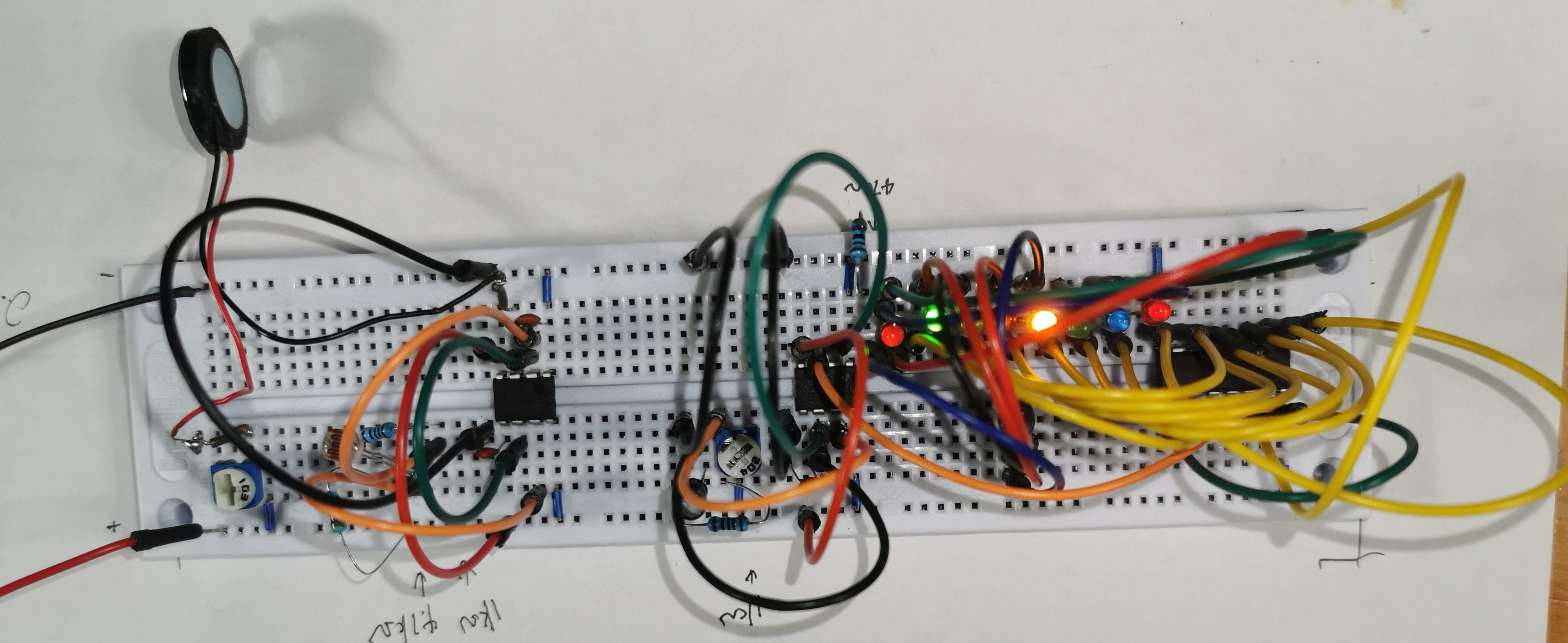
Following the design, I connected the circuit on the breadboard to test if it works.
Step 3: Connect the Perfboard
Once succeeded in connecting the breadboard (however, there was a small mistake, see below in “Problem” part)
This is my first time using both the soldering iron and the perfboard, it did take me a lot of time to learn and get familiar with these staff. I first completed the first part of the circuit, the one with NE555 and the speaker. Due to the narrow space between the holes in the perfboard, I suffered a lot of short-cut problems. Sometimes the NE555 turned to be extremely hot while other times, the circuit is not stable due to some of the loose points. However, I finally made the first step.
After that, I connected two perfboards together (because one perfeboard is too small). Then, I connected all the other components.
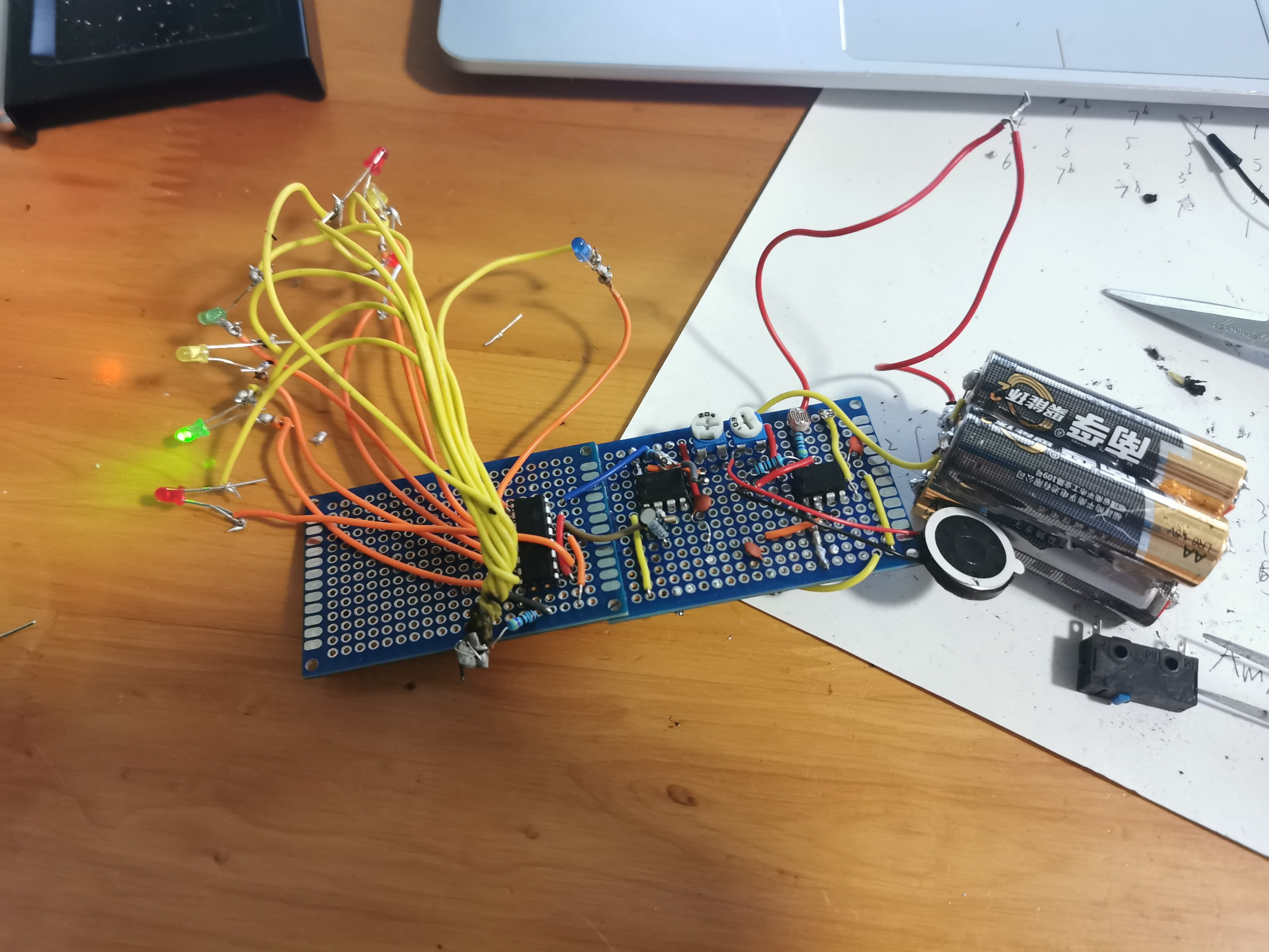
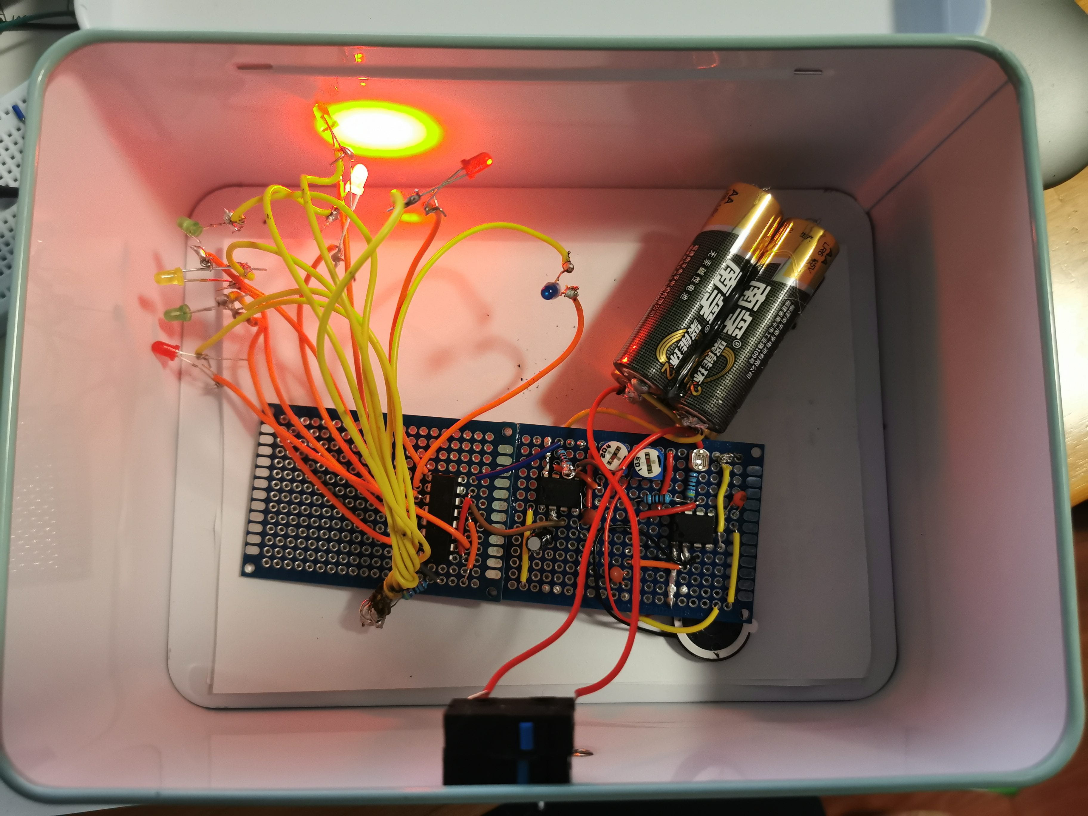
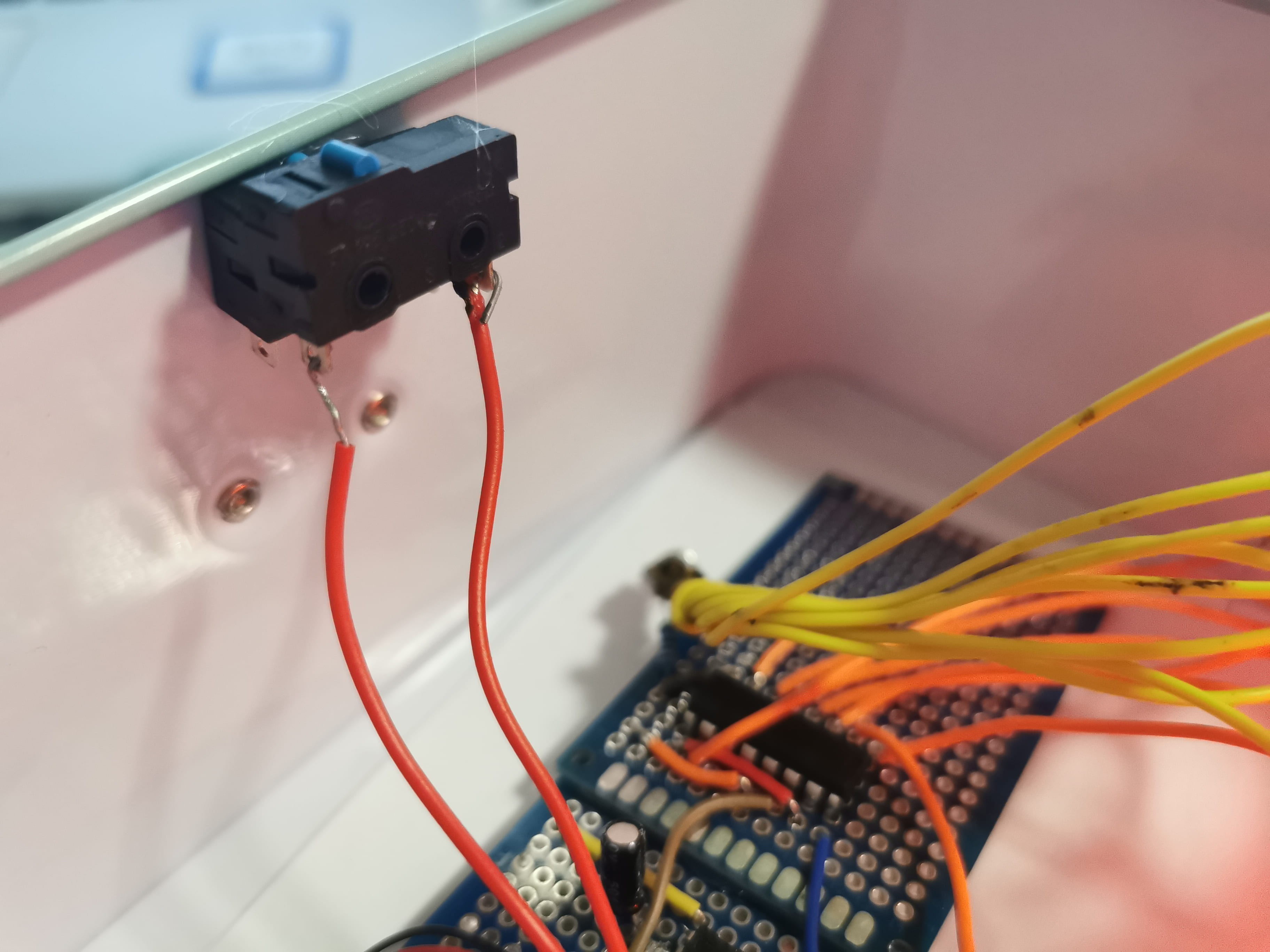
Finally, I put all the components into the iron box, and connected the switch to it.
Final Work
This video is how my entire project looks like.
Problem
Actually, the breadboard project wasn’t successful. Though I have checked the circuit a thousand times, it still cannot shine normally. Barry and Tom can neither find the reason. Basically, while I was adjusting the Rheostat for the speaker, the frequency of the shining of lights also changes accordingly. See the video below.
We used to doubt there’s something wrong with my CD4017 ID, but later the CD4017 worked well on the perfboard. So, I now doubt that there’s some shortcut on my breadboard. And one possible problem is that the NE555 of the speaker is mistakenly connected to the CD4017.