Experiment Name: Voltage Controlled Oscillator
Conducted By: Jamie, Clover, Michael (Tianyu), Tom, Anpu, Harry
Conducted On: Mar 8, 2020
Background
The 555 timer IC is an integrated circuit (chip) used in a variety of timer, pulse generation, and oscillator applications. The 555 can be used to provide time delays, as an oscillator, and as a flip-flop element. Derivatives provide two (556) or four (558) timing circuits in one package. In this experiment, we’re going to try making a voltage-controlled oscillator and find out the relationship between the sound and the components we have.
Materials
Here is a list of materials I used in this lab:
- A breadboard
- A NE555
- 2 200kΩ potentiometers
- A 1kΩ resister
- Two 100Ω resisters
- A speaker,
- A 0.01μF capacitor
- 4 1.5V some batteries
Hypothesis
- the larger (lower) the potentiometer connected to PIN 7 is, the frequency of the sound is lower (larger).
- the larger (lower) the capacitor’s value is, the lower (larger) the frequency of the sound is.
- the low resistance is connected to the speaker, the larger volume of the sound is.
- the larger the whole voltage of the circuit is, the higher the frequency of the sound would be.
Procedure
- Building up the physical circuits.
- Change the parameters of the components, hearing the sound and find their relationship.
- the potentiometer connected to PIN 7.
- the capacitor.
- the resistor connected to the speaker.
- The voltage of the whole circuit.
- Simulation analysis
- Conclusion
- A Strange Question
Step 1: building up the physical circuits.
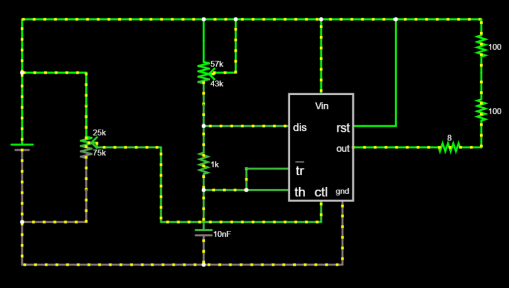
This is the original diagram that I referred to.

Due to the difference in the material we have, the following is the exact circuit I used for this lab.

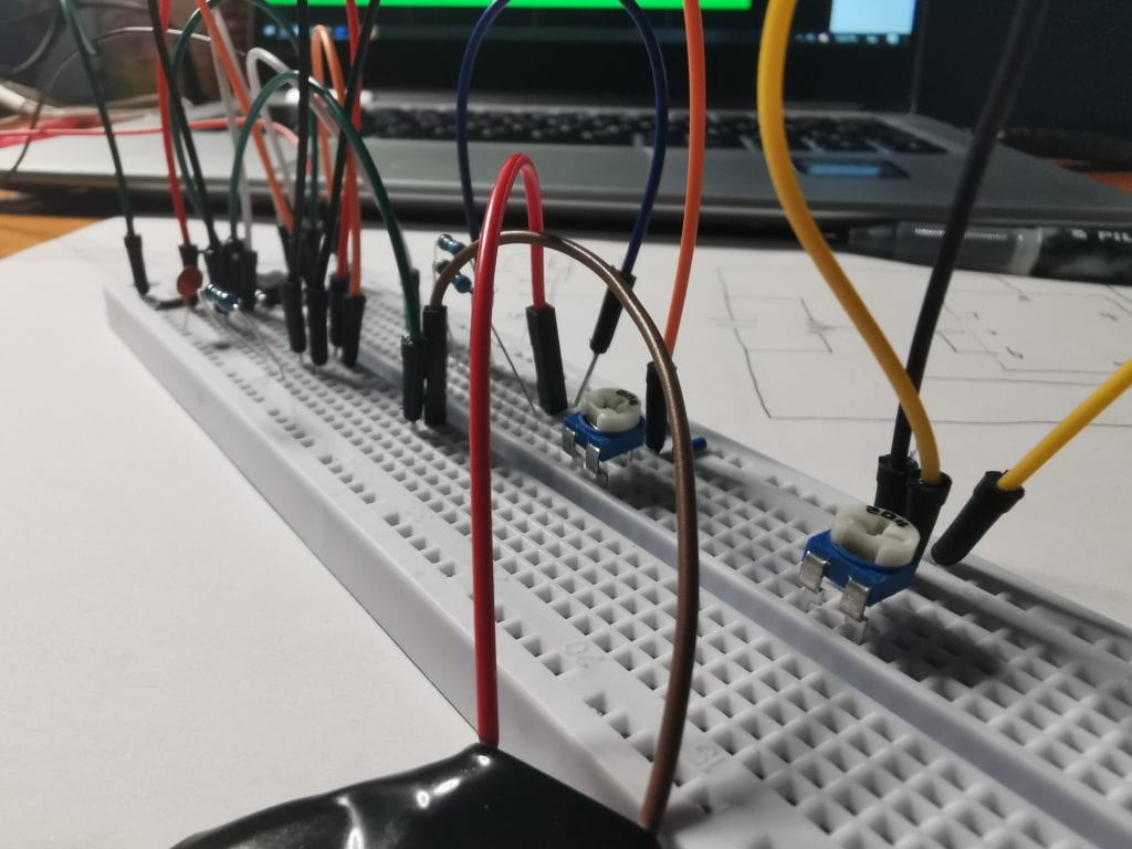
And this is the final physical circuit.

Step 2: Find out the changes with different components.
2.1 the potentiometer connected to PIN 7
By changing the resistance of the potentiometer, it turned out that the larger (lower) the potentiometer connected to PIN 7 is, the frequency of the sound is lower (larger).
However, an error occurs when I am doing this test, I’ll demonstrate it at the end of this report and raise a question about this.
2.2 the capacitor
I changed the 10 nF capacitor into 100 nF, 1 μF and 1nF. By comparing the result, I found that the larger (lower) the capacitor’s value is, the lower (larger) the frequency of the sound is.
2.3 the resistor connected to the speaker
I used an additional wire to short out the resistor connected to the speaker. When I short out one resistor, the sound got larger, when I short out another, the sound got larger again. As a result, the low resistance is connected to the speaker, the larger volume of the sound is.
2.4 The voltage of the whole circuit
By adding the number of batteries, it turned out that the voltage of the whole circuit has nothing to do with the frequency of the sound (or no extinct effect), but the larger the voltage is, the higher the volume is.
Step 3: Simulation Analysis
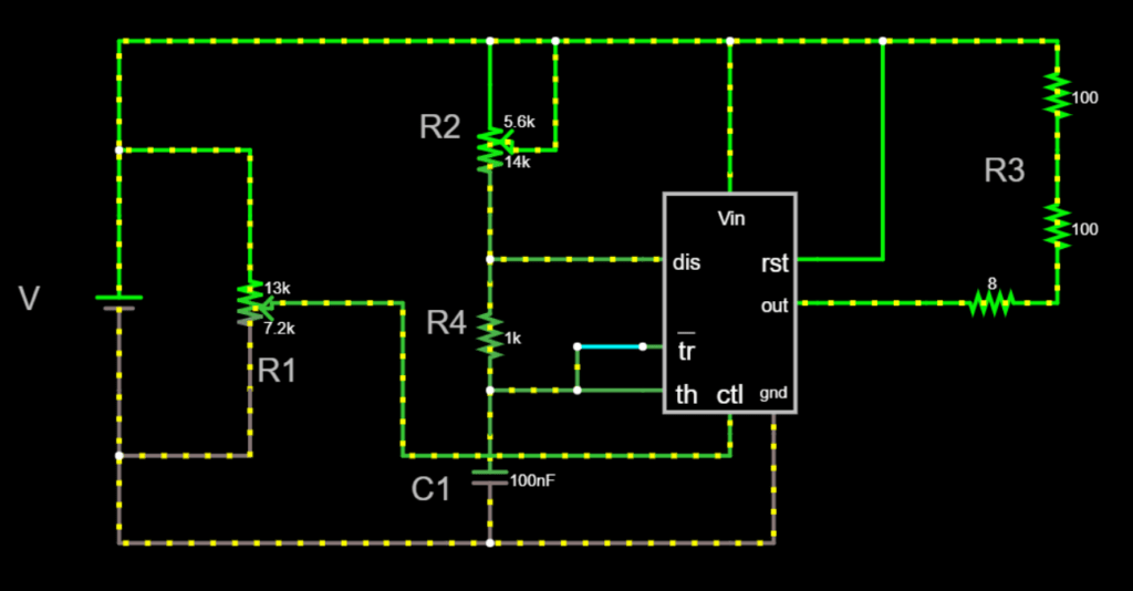
By using the online simulator, I found out different components’ influence on the sound of the speaker (all components are labeled below):

| Sound Change When the Components’ Value Increase | ||
| Component | Frequency of Sound | Volume of Sound |
| V | \ | ↑ |
| C1 | ↓ | \ |
| R1 | ↓ | \ |
| R2 | ↑ | \ |
| R3 | \ | ↓ |
| R4 | ↓ | \ |
Conclusion
By doing the experiments above, I am able to draw the following conclusions:
- the oscillating output of 555 in astable mode is a square wave with one pure frequency
- when connecting a speaker on the OUTPUT PIN, the speaker will make a constant and stable “bee” sound, the higher the oscillating frequency, the higher the sound pitch; and vice versa.
- different componrnts can effect the sound differently, to increase the frequency of the sound, we can:
- Decrease C1
- Decrease R1
- Increase R2
- Decrease R4
And to increase the volume of the sound, we can
-
- Increase V
- Decrease R3
Vice versa.
A Strange Question
Problem Raise
While I was conducting the experiment, everything worked out well. But as I was decreasing R2, the speaker are making a sound with a higher and higher pitch and suddenly stopped. I tried to change every component, but it just doesn’t work. So I suppose the speaker is broken. But how could it broken with the high frequency of the circuit?
Further Exploration
When I tried to lower R3, which the speaker was directly connected to, the sound came out again. However, this sound doesn’t have a stable frequency, it raises up first and then changes randomly. How could this happen? Below is a video I shot to help demonstrate.
https://www.youtube.com/watch?v=xF3ITWNMefg