Experiment Name: Voltage Controlled Oscillator
Conducted By: Jamie, Clover, Michael (Tianyu), Tom, Anpu, Harry
Conducted On: Mar 8, 2020
Circuit Diagram
This is the original diagram that I referred to.

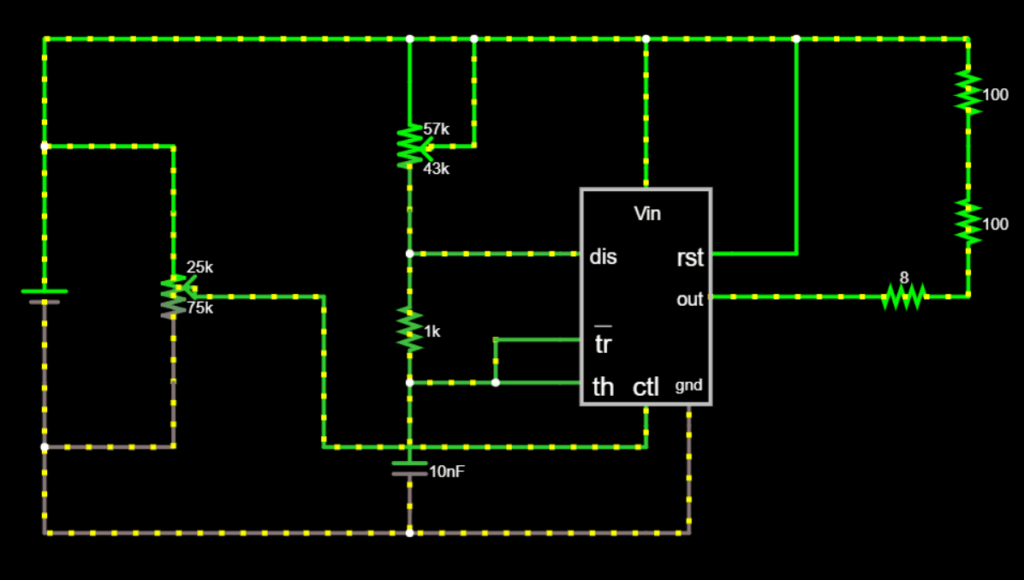
Due to the difference in the material we have, the following is the exact circuit I used for this lab.
Materials
Here is a list of materials I used in this lab:
- A breadboard
- A NE555
- 2 200kΩ potentiometers
- A 1kΩ resister
- Two 100Ω resisters
- A speaker,
- A 0.01μF capacitor
- 4 1.5V some batteries
Circuit
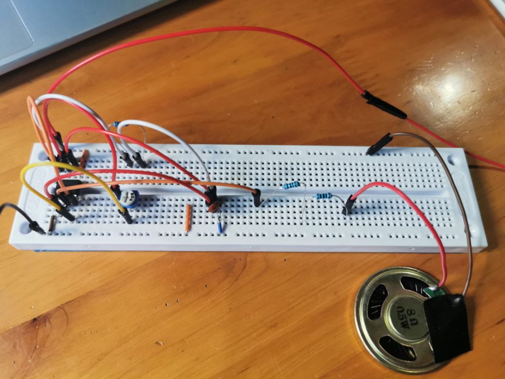
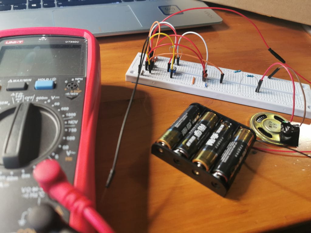
Here are the pictures of my breadboard:
When the power is on, we can hear the beep sound.
One mistake I made
When designing the circuit, I tried to work with the following draft:
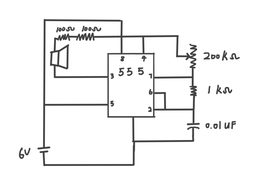
One thing I didn’t notice was that in this circuit, there’s actually a shout out problem. I finally found out this issue by using the online simulator.

Bad Speaker
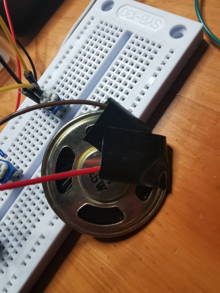
My speaker also had a bad connection. Since I do not have a soldering iron, I used tapes to stick it.
