Recitation 9: Digital Fabrication
This week, we were asked to create a kinetic sculpture using digital fabrication tools.
This project required collaboration, so I teamed up with Hanwen Hu. I was Student A in designing one part of the stand.
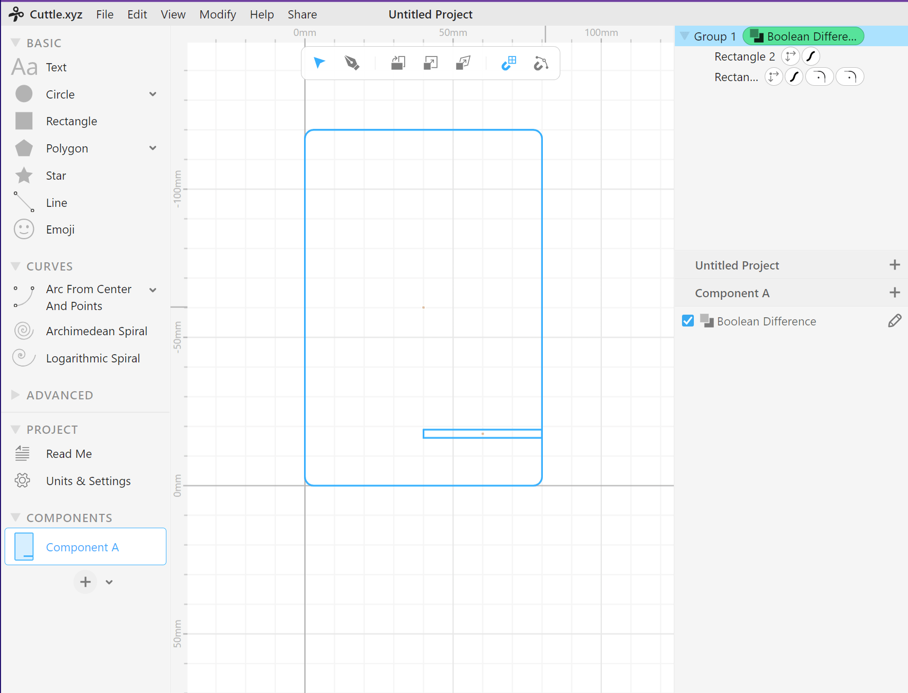
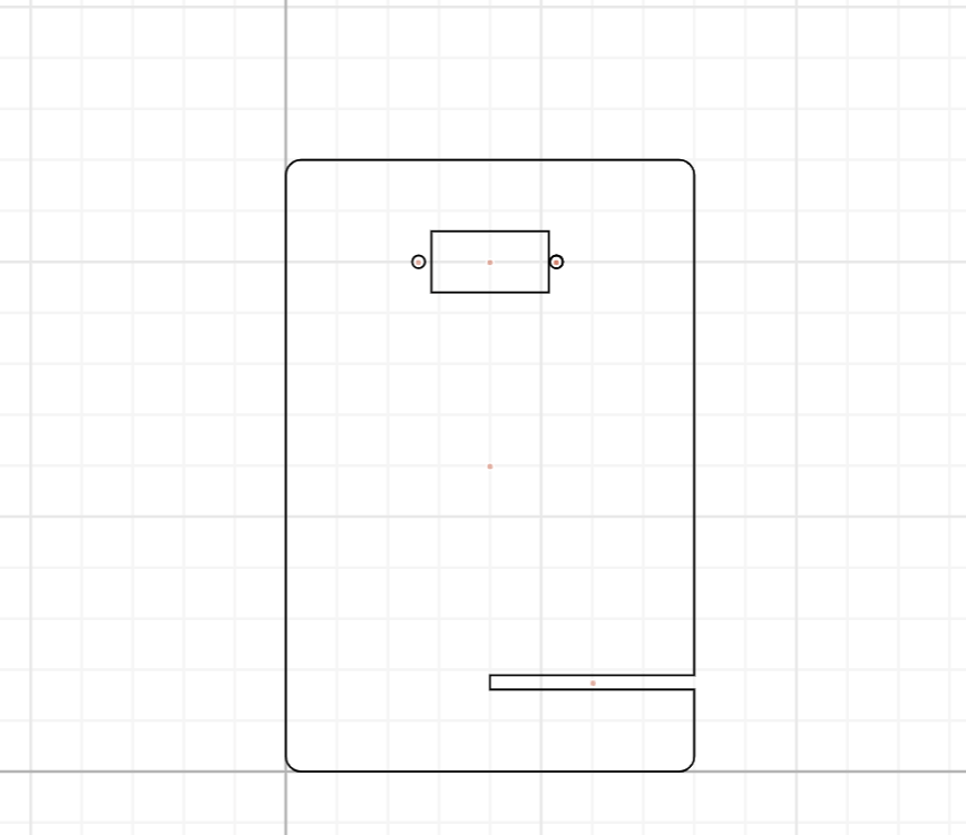
I chose the Grid Snapping mode to help me find the exact location of my components. Then I created an 80-mm-wide-and-120-mm-tall rectangle with round corners to be the body of the stand. Then, I drew another rectangle with a width of 40 mm and tallness of 2.8 mm and placed it on the right side of the big rectangle and -17.5 mm on the Y-axis. This rectangle would allow two parts of the stand to intersect.
I chose a “Boolean Difference” to make two shapes merge with each other. Then, I dragged another rectangle as the slot for the servo motor and positioned it at -100 mm on the y-axis, and center-aligned two rectangles horizontally. After this, I dragged two circles as the slot for the motor’s screw hole and used the values from Hanwen to modify the diameter of the two circles and the distance between the servo motor and the screw hole. And I finished the stand design.
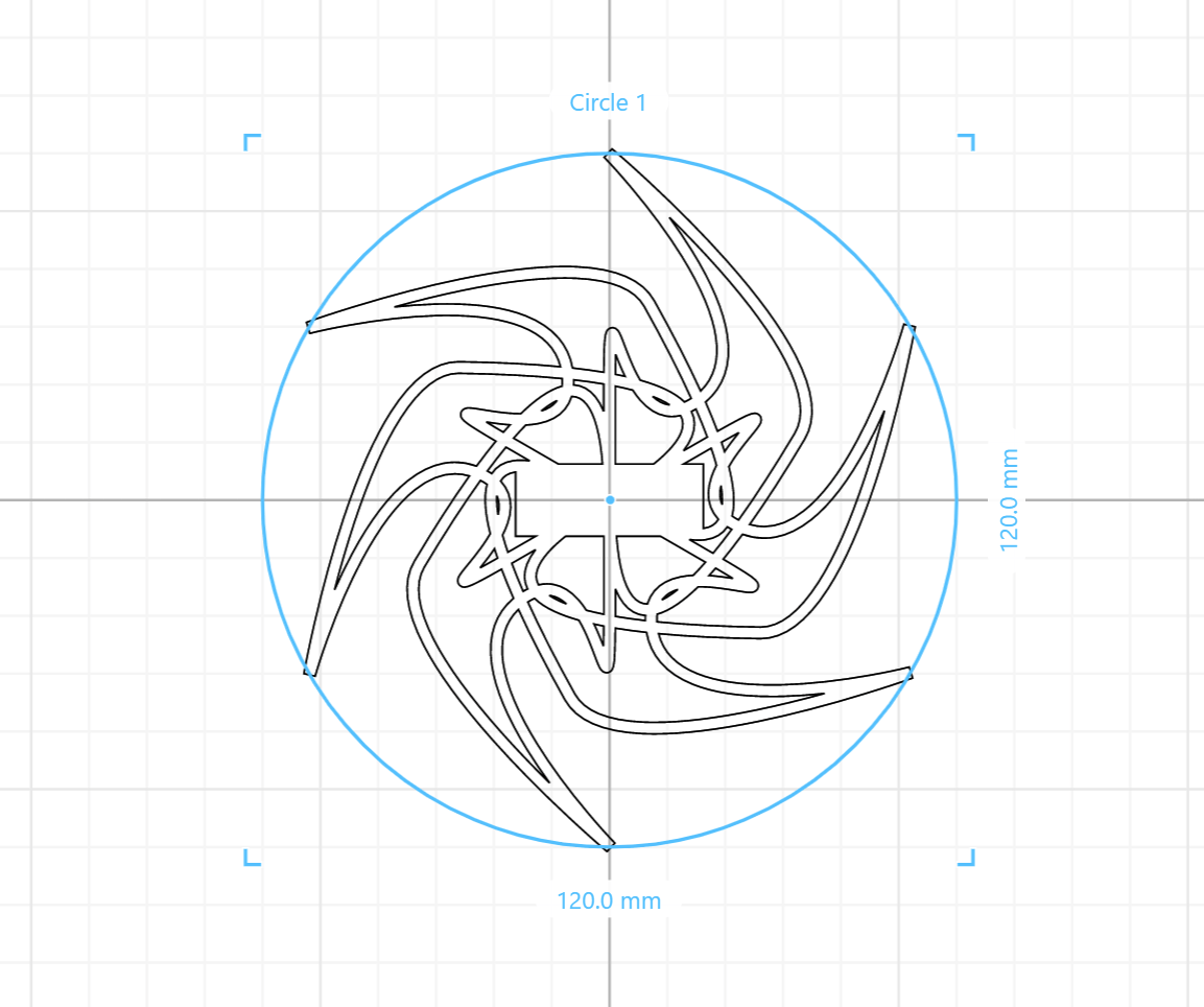
The next step was to create a circular pattern presenting visual effects within 120 mm in diameter. I used “pen” mode and created a pattern like this. And I also added the stroke to make it cuttable. 
Since my pattern would be attached to the stand, I cut a square out of it. Later in the laser-cutting part, however, Andy told me that one square would not suffice and that I needed two squares to form a solid structure.
The process of laser cutting:
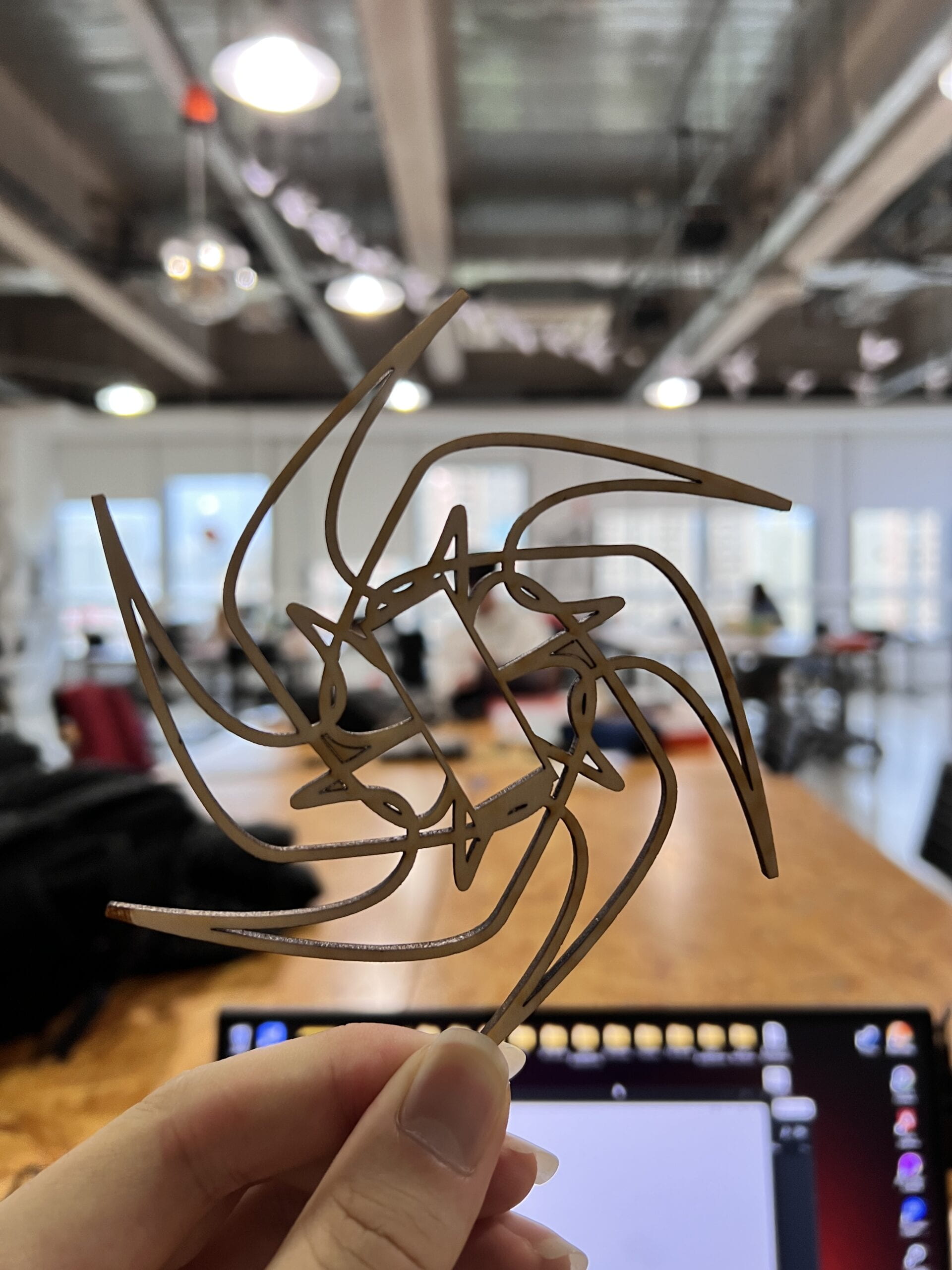
My pattern:

After ensembling, we had our sculpture ready to show.