Lab: Digital Input and Output with an Arduino
Having worked with Arduino before, I was sure I wouldn’t have any problems with the lab but I was wrong.
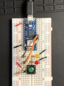
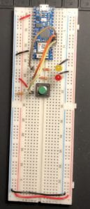
To start out, the setup of the breadboard was very clear from the schematics given. Arduino Nano 33 IoT was a new microcontroller to me but I was excited to work with something new. After getting the Nano setup on the board (see figs. 1 &2), it was time to input the code into the Arduino Integrated Development Environment (IDE). The code was provided so no major challenge there other than to make sure the correct ports (USB) and board (Nano) were selected. Besides switching the colors of the LEDs, I made no changes to the code provided. After verifying that I had no errors in the code, I press the button to upload the code to the Nano…

(Fig. 1)

(Fig. 2)

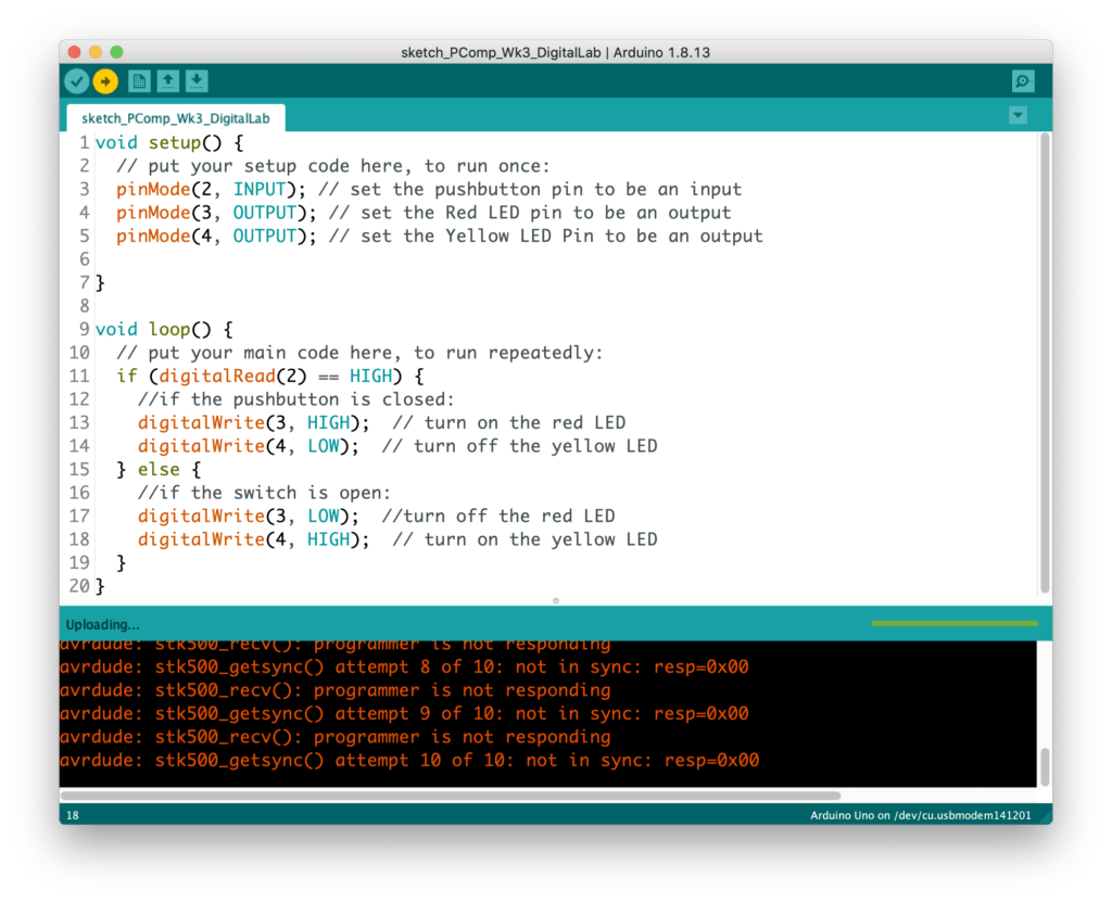
…Error #1
Nothing to worry about. I checked the Discord as others had similar errors. There was one person who received the same error message and it was a matter of a wiring issues. I checked my wiring, multiple times, with no luck. I ended up getting the same error. Someone on the chat also mentioned there being a possible connection issue with using a hub (multi-port adapter) to connect the Nano to the laptop. I did have a large hub with multiple USB-C, USB-A, SD card and HDMI ports so maybe that was the culprit. I was able to in my USB-C to USB-A Apple branded adapter; it couldn’t hurt to use the adapter that was designed by the same company as my
laptop…

…Errors #2 and #3
This error occurred twice. First after switching out the hub or the new adapter and, second, after testing a new USB-C cable which connects the Nano to the adapter. Fingers crossed…

…Error #4
I had overlooked resetting the board and the port which defaulted to their original settings after the few times I had changed the connection wires. I was able to reset those parameters and…

…Done Uploading / Possible Error #5
I was thrilled to see that the code was able to be uploaded but was curious as to the text listed in the console, as it was in orange, which tends to be a warning color. Nothing in the message stuck out to me so I proceeded to check out the board….
…Nothing.
What was I doing wrong!?! I took a step back and decide it was time to break out the multimeter. I checked that there was voltage running through the LEDs. With the button unpressed, the Red LED had a voltage of -1.78 and the Yellow that o 0.14. When I pressed the button, the Red had 0.13V and the Yellow had -1.82V. I was stuck at how the LEDs had negative voltage as they were wired properly from power to ground and I was using the correct leads of the multimeter to take the measure. So I decided to pullout the wires and try again…
…Still nothing.
I then proceeded to check that the LEDs had not burnt out; they were working. I checked and rechecked the wiring. I wanted to be sure I had done all I could before reaching out for help. Looking back, I would have saved time had I reached out earlier to the group but now I have all this documentation!
By accident, I stumbled upon something that I puzzled me even more than the current situation. When I was testing the LEDs’ voltage, I shorted one of the LEDs by touching both legs of the LED with on of the multimeter’s leads…
…It worked!
The yellow light was lighting up when the Red LED was shorted and the button was not pressed. This wasn’t exactly what I wanted, and was concerning as I didn’t want the short circuit to damage the Nano, but I was making progress. I tested next if I could get the Red LED to light up by shorting the Yellow…
…It worked!
I had reached a point where I was not able to learn anymore from this lab so I reached out for help. I still don’t understand why shorting out the LEDs worked, but I will find out. Shortly after asking or help, Viola He had solved my problem. As I had never used the large breadboard before, I was unaware that the grand power conduits do not connect down the sides. Around row 30, there is a break in power and ground. All I needed to do was to connect the two halves and…
…Lab #1 complete.
Lab: Analog In with an Arduino
Next I setup the breadboard with the potentiometer which went smoothly. After the issues in the digital lab I felt I was better prepared for this lab.

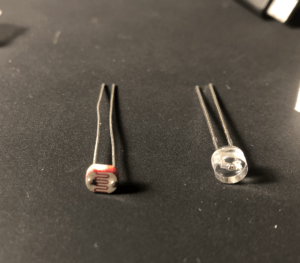
Next, I setup the breadboard for the photo cell. I used originally the photo sensor but the range of input was so low (0-40) I was worried something was wrong. I decided to try out a photo resistor I had on hand which had a range of 0-400. I have previously worked with this component in a project so I was familiar with it’s serial output. In comparison, this was much more useful.


…additional exercises in progress..
Questions:
- Why are there 2 GND pins on the Nano?
- Why is the large bread board made with a vertical break between the ground and the power?
- What is the difference between the photo resistor and the photo cell and the photo transistors?
- How do you slow the Serial Monitor down so that you can actually read the output?