Category Archives: Physical Computing

Physical Computing classwork

PComp Week 3: Group Project Planning and Labs

Group Project Planning:

For this week’s group project, I am paired with Yona Ngo and Yonatan Rozin.  We were drawn towards building a wearable piece that had a COVID influenced interaction but also something humorous.    We decided to make a piece that warned someone when they were too close to the user.  Below is our preliminary design for the piece by Yona
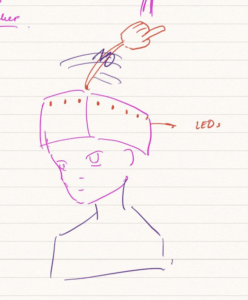
COVID Wearable Warning Hat

The hat will feature a sensor placed in the back of the hat that will trigger LEDs to flash, a finger to wave, and a speaker to create pitches at the intruder.  The pitches will be in an ascending pattern in an attempt to mimic someone saying “no, no, no” while wagging a finger.  We thought this would be a cute and humorous piece during this stressful time. 

Production Plan:
Since we are all in NYC, we  will be meeting this weekend/this coming week at 370 Jay Street to build this piece. 

We will use the following to produce the piece:
– Ultrasonic Ranger
– LED’s
– Several 220 Ohm resistors
– Servo motor
– 9V DC battery with snap connector
– Arduino
– Cardboard
– Copper tape
– plus other items we are missing…

Questions we will need to answer:
– How far can the ultrasonic ranger pickup distance from?  Hopefully 6ft?
– Will be have enough voltage with the 9V to power everything?
-If we are not all able to meet in person due to scheduling, how will we divide up the work?

Labs:

Lab: Tone Output Using An Arduino

When I started this lab, I had a few initial questions.  I wanted to add wires or headers to the ends of the FSR but I could not locate the videos Tom Igoe posted where he demonstrated how to do that.  I decided top ake a stab at it myself which was mostly successful.  Also, I did not have the necessary 100 Ohm resister or this project.  I’m not sure exactly how it effected the lab but I did have issues.  Since I didn’t have a 100 ohm resister I used the closest one i had, a 220 Ohm. 

I setup the boards and uploaded the program but was not able to get any reaction out o the 2nd FSR.  Is it supposed to have impact on the tone?
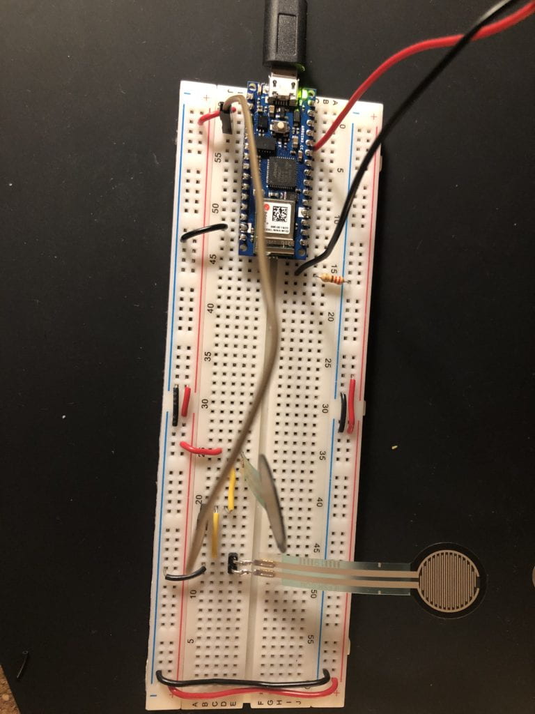
Tone Lab 1 Breadboard Setup

Musical Tones:
Got the music to play!

Last one:
Got the setup right but still with the 220 ohm resister instead of the 100 ohm connecting the speaker to ground.   I had a similar issue as with the first lab.  Only the second sensor was able to get a noise to play.Tone Lab with 3 FSR
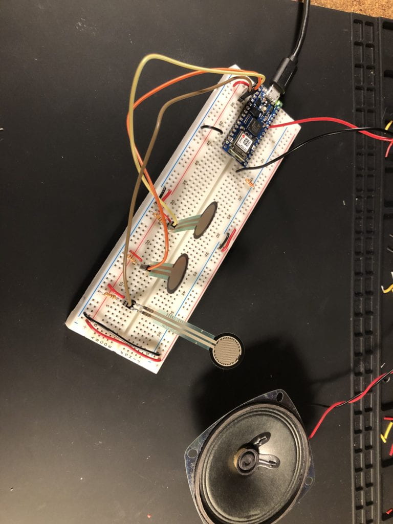

 
Lab: Servo Motor Control with an Arduino

To start, I pulled out the pieces I needed and noticed something odd with my servo motor, it had a 4th wire.  I have an Analog feedback Micro servo motor S1123 from Adafruit. Per their site, the additional wire is “the feedback (potentiometer wiper) line is brought out to a fourth white wire. You can read this wire with an analog input such as those on an Arduino, to get the servo’s position. “  That answer that question but how do I figure out which of the other 3 wires goes where.   The wires are Brown, orange and a yellow/orange.  None of which follow the color scheme I am familiar with.  in order to figure out which was ground and which was power, I watched the video on Adafruit’s site.  Unfortunately, I think my guess was incorrect as you will see in a moment. 

When I setup the breadboard originally, the FSR was not reading.  Instead o testing the wiring, I decided to try a different component as I was concerned the FSR was not working properly.  That switch created the same result, nothing.  Next I took a look at the wiring and there was the culprit; I  had the wire from GND of the FSR going into the wrong pin of the Nano.  Once corrected, I tested the output of both the potentioneter and the FSR successfully.  Next came programming for the motor and testing.
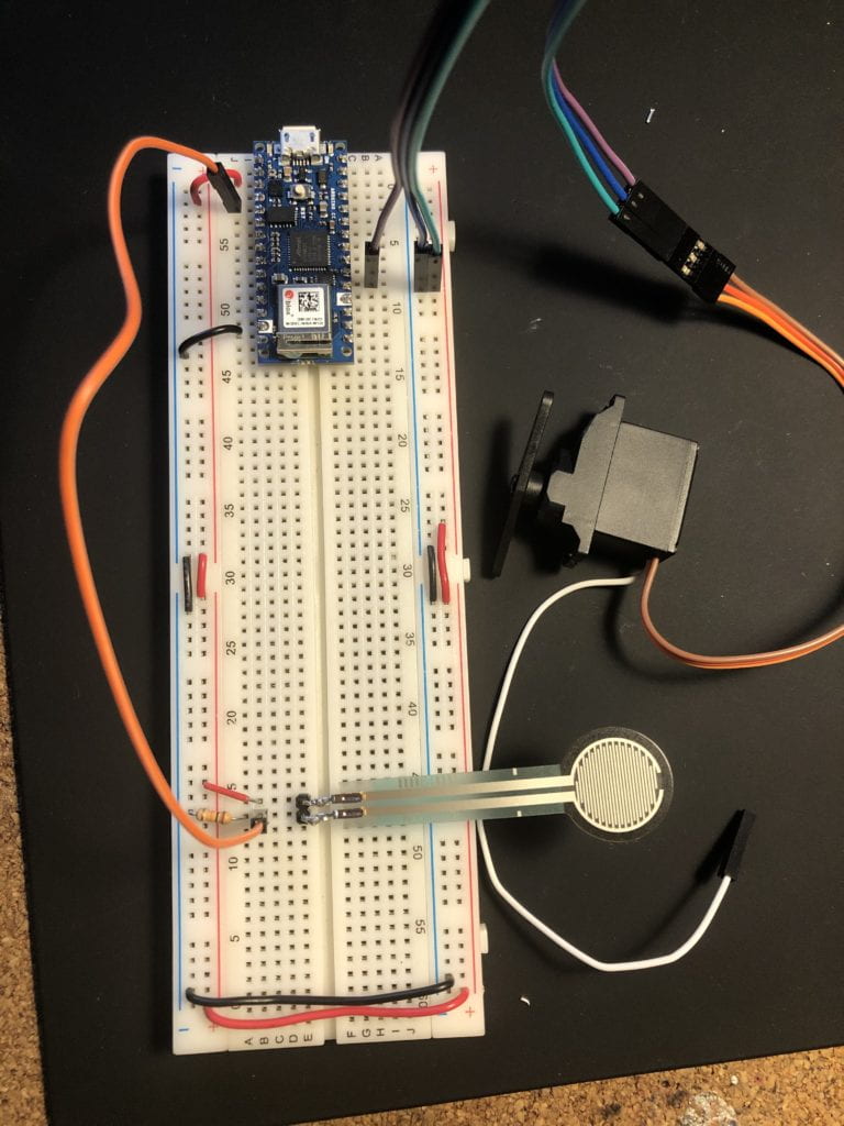
Servo Motor Breadboard Setup

I was able to get the code setup as needed with very little challenges.  The challenge I had was getting the motor to work.  I went with my initial wiring configuration guess, then tried a few others and still nothing.  I decided it was time to call is a night and schedule some time for additional help with these assignments. 
 

PComp Week 2: Digital and Analog Input/Output

Lab: Digital Input and Output with an Arduino

Having worked with Arduino before, I was sure I wouldn’t have any problems with the lab but I was wrong.

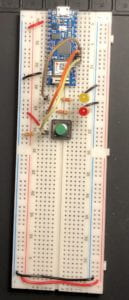
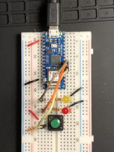
To start out, the setup of the breadboard was very clear from the schematics given. Arduino Nano 33 IoT was a new microcontroller to me but I was excited to work with something new. After getting the Nano setup on the board (see figs. 1 &2), it was time to input the code into the Arduino Integrated Development Environment (IDE). The code was provided so no major challenge there other than to make sure the correct ports (USB) and board (Nano) were selected. Besides switching the colors of the LEDs, I made no changes to the code provided. After verifying that I had no errors in the code, I press the button to upload the code to the Nano…

Closeup of Circuit
(Fig. 1)

Full view of circuit (large breadboard)
(Fig. 2)

Error 1

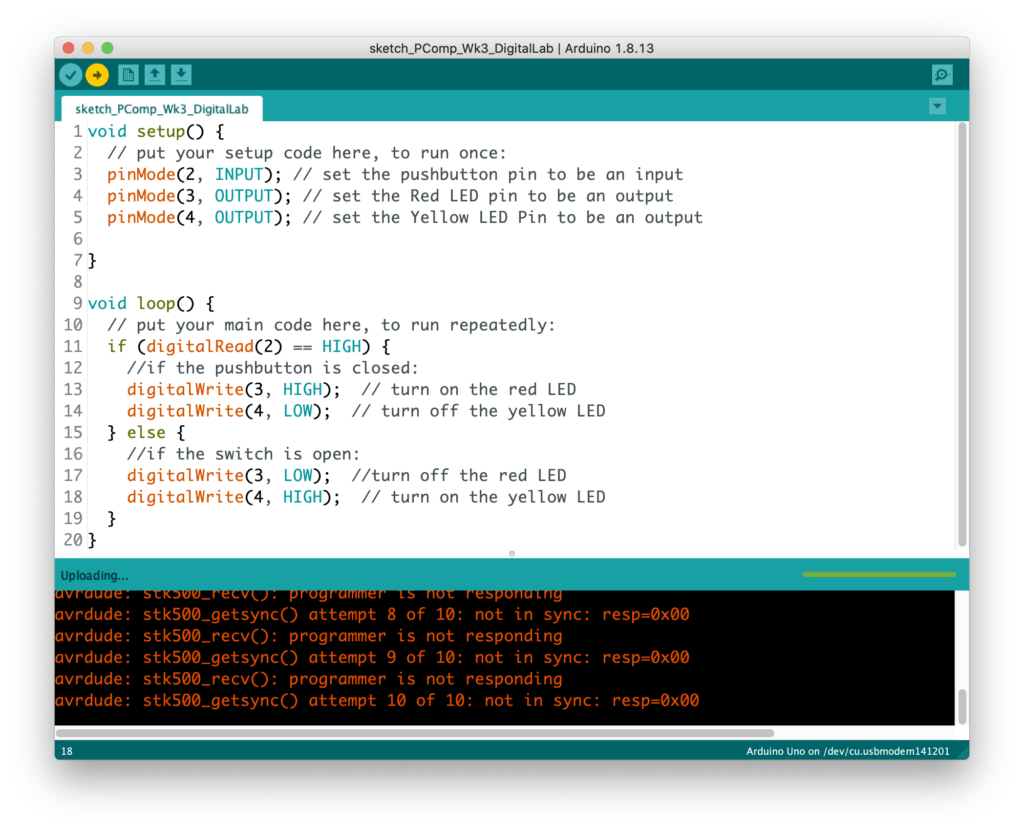
…Error #1

Nothing to worry about. I checked the Discord as others had similar errors. There was one person who received the same error message and it was a matter of a wiring issues. I checked my wiring, multiple times, with no luck. I ended up getting the same error. Someone on the chat also mentioned there being a possible connection issue with using a hub (multi-port adapter) to connect the Nano to the laptop. I did have a large hub with multiple USB-C, USB-A, SD card and HDMI ports so maybe that was the culprit. I was able to in my USB-C to USB-A Apple branded adapter; it couldn’t hurt to use the adapter that was designed by the same company as my
laptop…

Error 2 and 3

…Errors #2 and #3

This error occurred twice. First after switching out the hub or the new adapter and, second, after testing a new USB-C cable which connects the Nano to the adapter. Fingers crossed…

Error 4 Not port or board selected

…Error #4

I had overlooked resetting the board and the port which defaulted to their original settings after the few times I had changed the connection wires. I was able to reset those parameters and…

Error 5 - Done Uploading

…Done Uploading / Possible Error #5

I was thrilled to see that the code was able to be uploaded but was curious as to the text listed in the console, as it was in orange, which tends to be a warning color. Nothing in the message stuck out to me so I proceeded to check out the board….

…Nothing.

What was I doing wrong!?! I took a step back and decide it was time to break out the multimeter. I checked that there was voltage running through the LEDs. With the button unpressed, the Red LED had a voltage of -1.78 and the Yellow that o 0.14. When I pressed the button, the Red had 0.13V and the Yellow had -1.82V. I was stuck at how the LEDs had negative voltage as they were wired properly from power to ground and I was using the correct leads of the multimeter to take the measure. So I decided to pullout the wires and try again…

…Still nothing.

I then proceeded to check that the LEDs had not burnt out; they were working. I checked and rechecked the wiring. I wanted to be sure I had done all I could before reaching out for help. Looking back, I would have saved time had I reached out earlier to the group but now I have all this documentation!

By accident, I stumbled upon something that I puzzled me even more than the current situation. When I was testing the LEDs’ voltage, I shorted one of the LEDs by touching both legs of the LED with on of the multimeter’s leads…

…It worked!

The yellow light was lighting up when the Red LED was shorted and the button was not pressed. This wasn’t exactly what I wanted, and was concerning as I didn’t want the short circuit to damage the Nano, but I was making progress. I tested next if I could get the Red LED to light up by shorting the Yellow…

…It worked!

I had reached a point where I was not able to learn anymore from this lab so I reached out for help. I still don’t understand why shorting out the LEDs worked, but I will find out. Shortly after asking or help, Viola He had solved my problem. As I had never used the large breadboard before, I was unaware that the grand power conduits do not connect down the sides. Around row 30, there is a break in power and ground. All I needed to do was to connect the two halves and…

…Lab #1 complete.

Lab: Analog In with an Arduino

Next I setup the breadboard with the potentiometer which went smoothly. After the issues in the digital lab I felt I was better prepared for this lab.

Potentiometer Analog Circuit

Next, I setup the breadboard for the photo cell. I used originally the photo sensor but the range of input was so low (0-40) I was worried something was wrong. I decided to try out a photo resistor I had on hand which had a range of 0-400. I have previously worked with this component in a project so I was familiar with it’s serial output. In comparison, this was much more useful.

Photocell Full Circuit
Full Analog Photocell Circuit
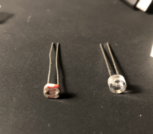
Photo Resister and Photo Sensor
Photo Resister (left) and Photo Sensor (right)


…additional exercises in progress..

Questions:

  • Why are there 2 GND pins on the Nano?
  • Why is the large bread board made with a vertical break between the ground and the power?
  • What is the difference between the photo resistor and the photo cell and the photo transistors? 
  • How do you slow the Serial Monitor down so that you can actually read the output?

PComp Week 1: Labs and more

I’d like to start out with the final project in this week’s selections of reading and labs: 

Creative Switches in Series

Inspiration:
Like the majority of the world, masks and sanitizer have become necessary additions to our daily routine.  What better everyday activity to use as inspiration than one we all wish wasn’t.   I decided to build this circuit around an instance of coming home from a walk. 

Process:

Initial Sketch
Initial sketch mapping out the three switches.

After I had the basic idea mapped out, I started building the ring switch.  I first had to make sure the ring was going to be able to carry a current, which luckily it did.  Then came the actual switch.  Initially, I was going to have the the action required for the switch be placing the ring on a flat surface with the two conductive contact points on either side (see picture below).  Unfortunately, the connection wasn’t strong enough so I decided to create a case to put the ring into which would close that switch. 

Ring switch attempt 1
Initial idea for the switch.
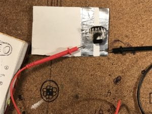
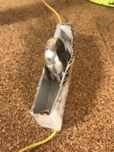
Final Ring Switch
Here is a closeup of the ring switch. The box is lined with aluminum foil and copper tape. When the ring is placed in the box, the switch is closed.

Next, I worked on the mask switch. 

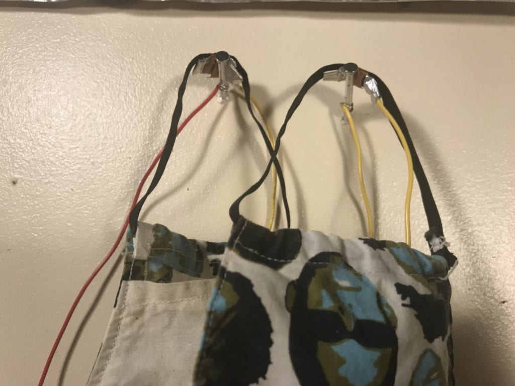
Since the nails used were not conductive, I needed to wrap them with aluminum foil so that they could be part of the switch.  Next I strung a wire in the pocket of the mask, connecting the two ear holds.  I used aluminum foil and copper tape to attach the wire to the elastic.  The copper tape was necessary as the aluminum duct tape was not conductive on its sticky side, unlike the copper tape.  Using the copper allowed me to wrap the connections without needing to use a separate glue. 

Closeup of mask switch
Here is a closeup of the closed mask switch.

With the two other switches working, I needed to figure out how best to create the cup pressure sensor.  I had created a fabric pressure sensor once before so I had a basic idea of how to proceed.  The challenge was be making sure the switch didn’t close before I poured the water into the cup.  I experimented with a few different cups and settled on a plastic one.  Ideally, I would have used a cup with a completely flat bottom but all the plastic cups I had on hand had curved bottoms.   

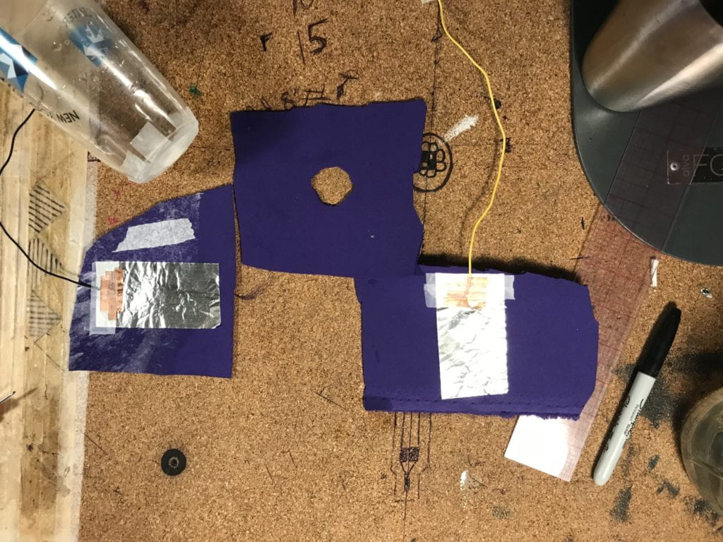
For the fabric switch, I initially made a 2 and 3/4 inch diameter circle in the neoprene which separated the two conductive sides of the switch.  Because the opening was so big, the switch closed before I could pour any water into the cup.  I then tired cutting a new piece of neoprene with a smaller opening, 7/8th of an inch across.  This size opening allowed the switch to stay open while waiting for the water to be poured, but did not close the switch once filled.  This was because the bottom of the cup was curved up which did not place enough pressure on the top layer of fabric even though the cup was full.  To fix this, I taped a small ball of paper onto the bottom of the cup which, once the cup was full, pressed down through the center hole closing the switch.   

Pressure switch
Here are the pieces of the neoprene pressure switch laid out.

Completing the Circuit

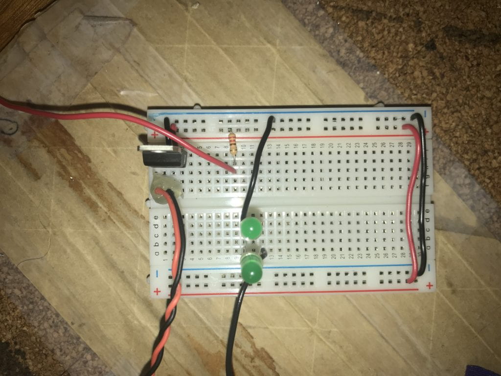
The final step was to connect the series of switches to the power via the breadboard.  I did not need to modify the setup much as I had just created a circuit with an LED and a potentiometer prior to working on this lab.  Here is a closer picture of my board layout. 

Breadboard View
 Just outside the picture is the 9V battery.
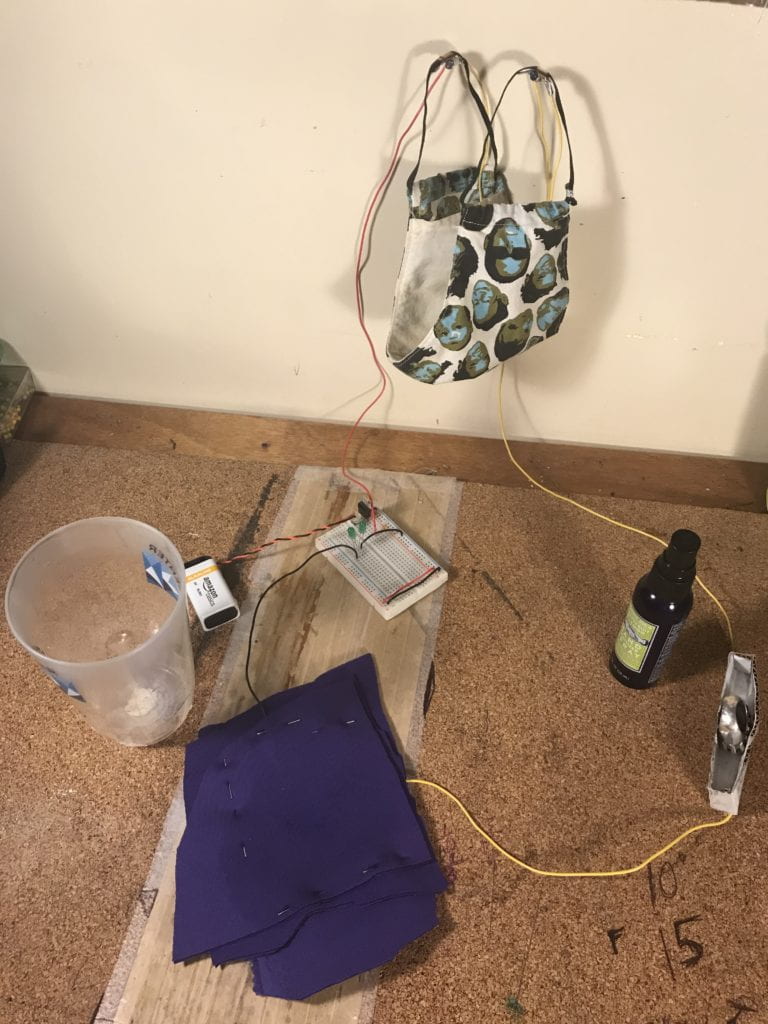
Final Circuit Setup
Full view of final circuit setup.

Switch Materials:

Switch #1: The Mask

  • Cotton mask with elastic
  • Aluminum foil
  • Copper tape
  • (2) Nails wrapped in aluminum foil
  • Wires

Switch #2: The Ring Box

  • Silver Ring
  • Cardboard
  • Aluminum Foil
  • Aluminum Duct Tape
  • Copper Tape
  • Scotch Tape
  • Wires

Switch #3: Glass of Water

  • (1) Plastic Cup
  • Neoprene
  • Aluminum Duct Tape
  • Copper Tape
  • Wire
  • Dress Pins
  • Water
  • Paper
  • Scotch Tape

Lab 1: Components

I found this lab to be very helpful as it allowed me to organize my supplies and equipment while getting a better handle on exaclty what I had on hand.   I now have a much better understanding of the components as well as confidence in being able to identify individual components. 

Here are a few pictures of my organizing progress:

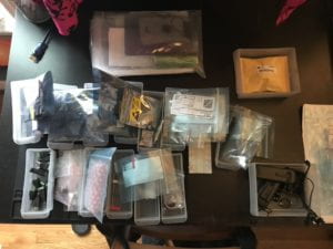
Components in Trays
Components out of the bags and into organizing trays.
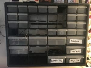
Organizer awaiting components
Organizer awaiting components and labels.


Lab 2: Breadboard

I decided to build the setup in this lab as I wasn’t entirely sure if this was a lab to report something or just an informative lab. I did, however, get to practice soldering headers to a 9V batter snap which came in handy for lab 3. 

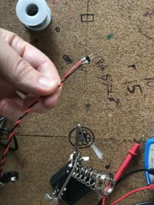
Pin Header
Close up of the my soldering work. I added pin heads to the ends of the 9V battery snap.  This image doesn’t show the layer of hot glue that was applied to the connection after to prevent a short circuit. 

Lab: Electronics

A few years back, I bought a DT-9205B Digital Mulitmeter but did not get too much use out of it.  I learned in the lab just how different multimeters can be.  Learning about my multimeter was insightful.  Unfortunately, the handbook for this particular meter was not entirely accurate when it came to identifying the icons on the front.  Through comparing the meetings shown in the lab and in the videos, I was able to figure out how my mulitmeter works and was able to take all the necessary readings for this lab. 

Lastly, here are a few questions I had from the readings:

  • When organizing electrical components, are there any precautions we need to take in regards to static?  And if so, which components do we need to be most concerned with?
  • Can we discuss more about pull-up and pull-down resistors and how they differ (type, location in circuit, etc.)?
  • Please explain relationship further the relationships happening in the equation Watts = Volts * Amps
  • When would we need to use the variable bench power supply ?
  • How does RC differ from DC/AC and what accommodations do we need to make in a circuit to use RC?
  • What is a voltage divider circuit?
  • With photocells going out of fashion due to their toxicity, are phototransistors equivalent?  Will these take the place completely of photocells and what do we need to know when using phototransistors in place of photocells?
  • Can you provide an example of when we would use a rotary encoder in a project?