Category Archives: Physical Computing

Physical Computing classwork

ICM/PCOMP Week 14: Speaker Matrix Installation Part 2

Final Project Documentation Part 1. 
Initial Project Blog

Part 2

Inspiration:

After my initial idea of utilizing retired sex toys for a game of Operation, I found inspiration in Daniel Rozin’s Mirror pieces as well as the following:

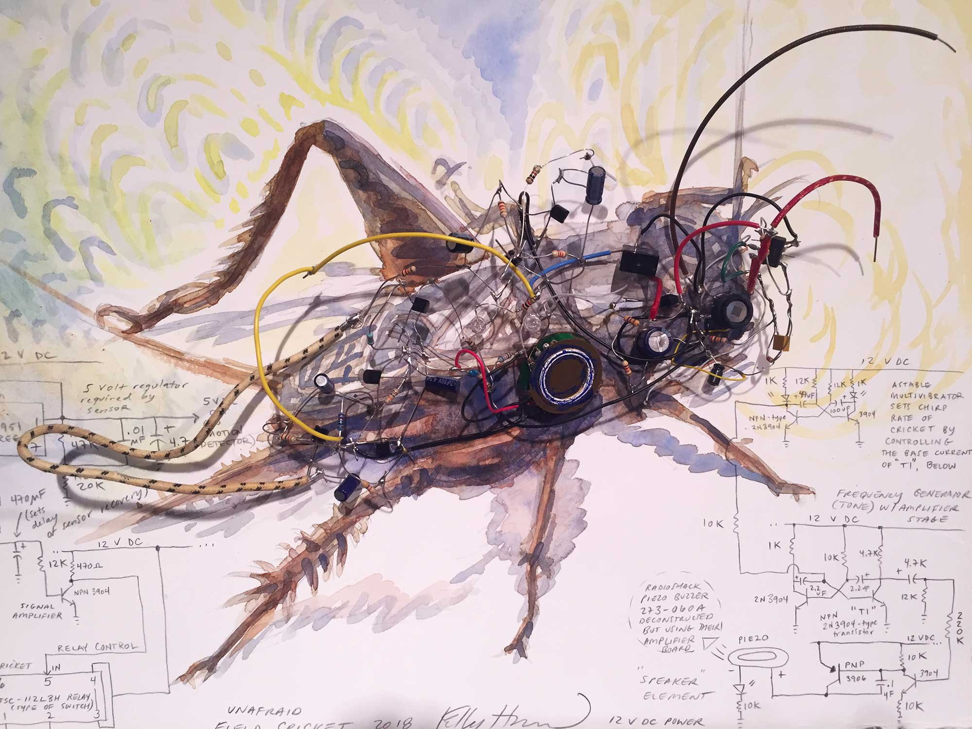
Thicket headphone installation
 Thicket (2016) by Maya Dunietz. Photo by Eldad Refaeli.
Cricket
Cricket by Kelly Heaton.
Iris Van Herpen Dress
Iris van Herpen, Voltage. 3D Print Collaboration with Neri Oxman


Music: Not Impossible

The SoundShirt

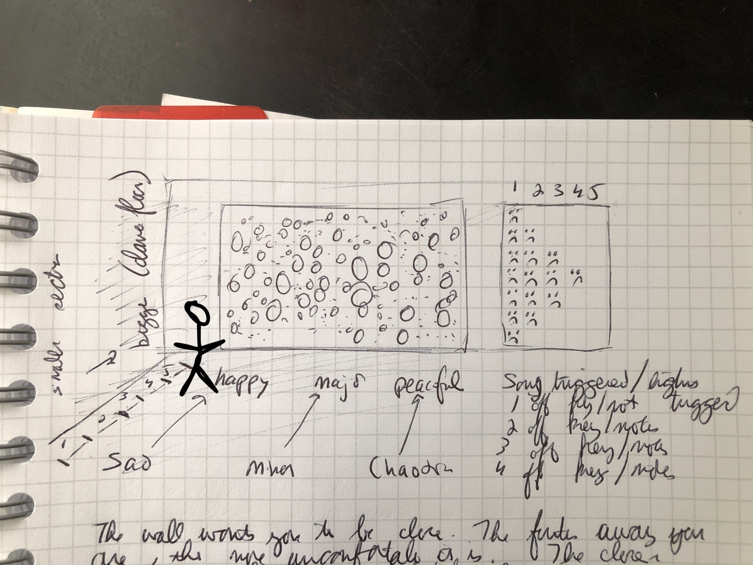
Design Sketch
Draft of Exhibition Interaction

Once I had a good sense of where I was going, I moved forward with experimentation.

Tear-down of  Headphones:

I used the following list of headphones.  The Apple earpods were old ones from my apartment and the others were found for free on the junk shelf at ITP. 

  • Headphones/Speakers:
    • 5 sets of Apple Headphones
    • 1 pair of metal headphone of unknown origin
    • 1 pair of Sony headphones
    • 1 pair of Panasonic XBS headphones
    • 1 pair of Insignia headphone

Referring to iFixit’s guide to Apple EarPods, I began but tearing down the sets I had on hand.  I used an Xacto knife to get the casing off, making sure not to cut the wires before I was able to test their connections. 

Working with Speakers:
Screenshot of iFixit reference page for teardown
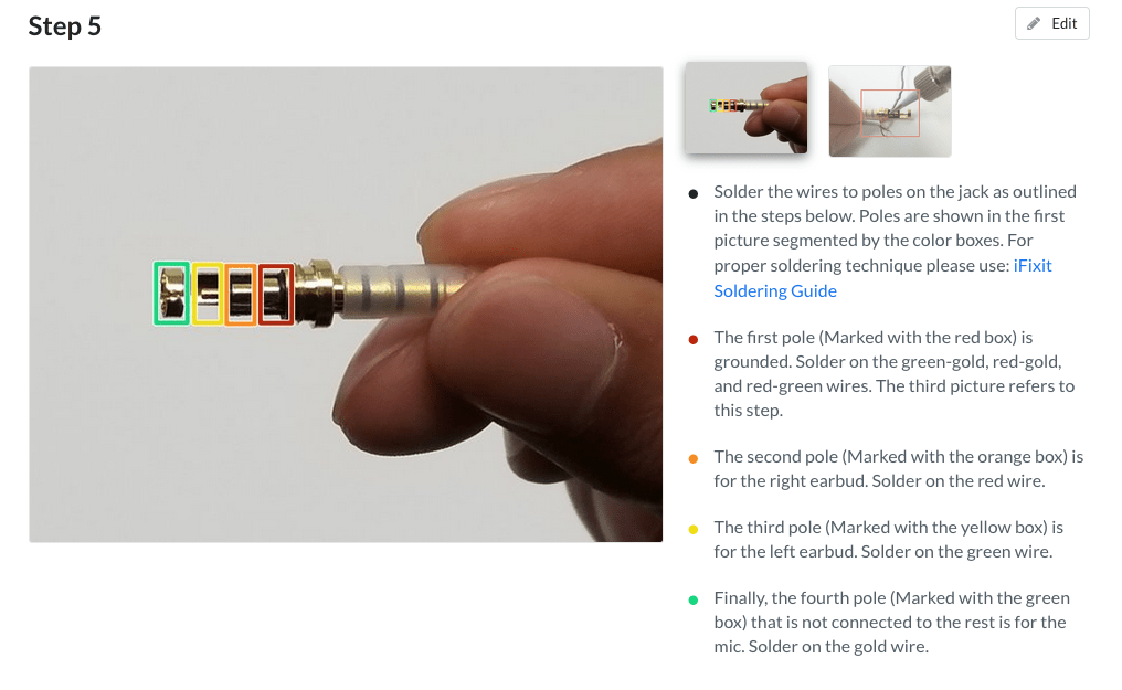
The above page was very helpful in figuring out the positive and negative wires for the speakers.  This is from iFixit’s site and can be found here.   All the speakers used a similar color coding for the wires.  The in wires were all either red or either with bronze wires.  The ground wires were all bronze.  In order to test that I was assigning the wires correctly, I used the following site along with a multi-meter.  This was specific to the Apple headphones but was transferable to the other sets as well. 

    • GND – Red-Gold and Green-Gold Wires
    • Connection labeled BB0 on the speakers
    • Voltage – Gold and Green
Non-Apple Ear Pods
Non-Apple Ear Pods Connects
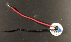
Speaker with new wires
Soldered wires onto speaker

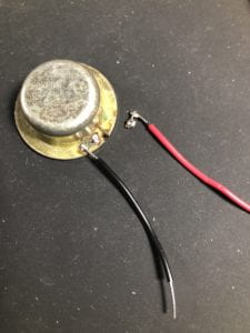
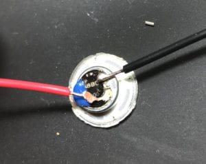
I did run into a challenge when soldering on the new wires (see below) where the soldering points would detach from the speaker casing.  I was able to reattach it using hot glue but only for the one speaker.  The second speaker shown below I have not been able to reattach that connection.  Later, when building the final piece, I covered the connections in hot glue in order to protect them. 
Detached Connection
Detached Connection Pad
Found Speaker Broken
Found Speaker with detached pad


In the end, tear-down went as expected.  Technology is not made to be taken apart.  I used a small knife and pliers in order to get the casings off.  I had to make sure not to tear a whole into the paper cones of the speakers when I was prying them apart.

Building the Circuit:

For all components, I started with one and scaled up.  At the very beginning, I started with 1 Nano 33 IoT, 1 LED and 1 Photo ResistorThis lab from class was helpful in beginning this project. 
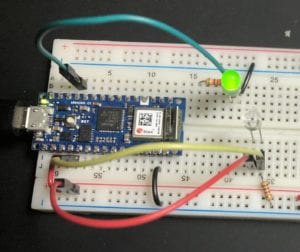
Circuit Photo Sensor and 1 LED

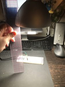
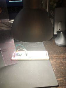
Next, I moved on to configuring the lighting rages in preparation for coding the interaction (varying distances from sensor would trigger different sounds and images).   Using a 40W LED light bulb, I measured the following

  • Sensor Range:
    • With a 40 W light bulb 12 inches away from the sensor
      • Bottom: 0-10
      • Top: 35-50
    •  40w bulb 12 inches away from sensor
      •  Bottom: 5-15
      • Top: 70-110
    • 40w bulb 6 inches away from sensor
      • Bottom: 40-60
      • Top: 430-510
Photo Testing Setup 6 Inches from light source
Photo Testing Setup 12 Inches from light source


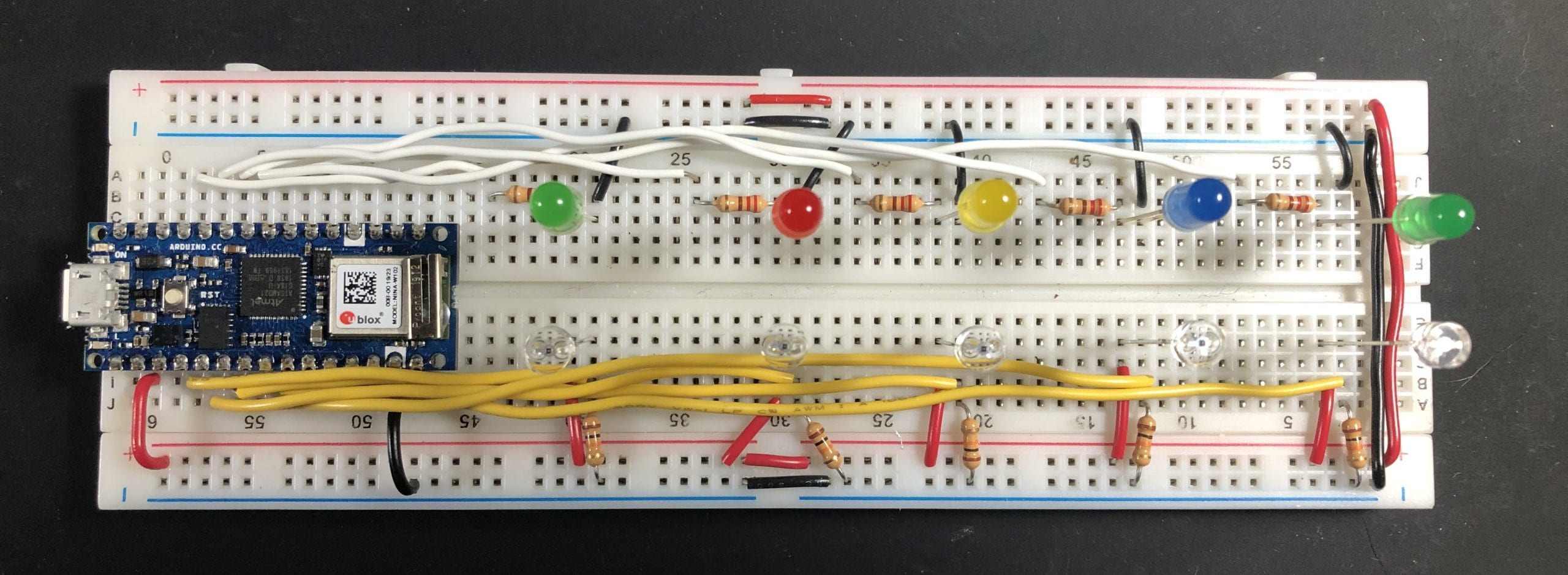
5 LEDs and 5 Photo Sensor:Breadboard 5 LEDS and 5 Photo Sensors

Breadboard Circuit 5 LEDS and 5 Photo Sensors 

Adding Speaker to Circuit:

Testing Speaker:
I think these have a resistor built in.
Resistance: .037
* Used multimeter on tone to see if there is a connection between the two
De-solder the connection then add new wires for testing
* With the new wires: .039
* Show picture of new wires
* Caution
* When soldering the new connections onto the speaker, I think the iron was too hot and the tracing lifted up on the rest of the case. I will have to encase the backing with hot glue to prevent it from coming apart.
* Research:
* Driver: https://www.quora.com/What-is-the-driver-specification-of-apple-earpods?share=1
* Patent:
* https://www.patentlyapple.com/patently-apple/2013/01/apples-patent-for-their-revolutionary-earpods-comes-to-light.html
* http://patft.uspto.gov/netacgi/nph-Parser?Sect1=PTO2&Sect2=HITOFF&p=1&u=%2Fnetahtml%2FPTO%2Fsearch-bool.html&r=4&f=G&l=50&co1=AND&d=PTXT&s1=175588&s2=apple&OS=175588+AND+apple&RS=175588+AND+apple

Once the LEDS and photo resisters worked well together, I added a speaker.  I used https://itp.nyu.edu/physcomp/labs/labs-arduino-digital-and-analog/tone-output-using-an-arduino/ for guidance setting up the circuit.  

Schematic:

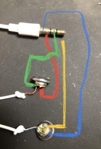
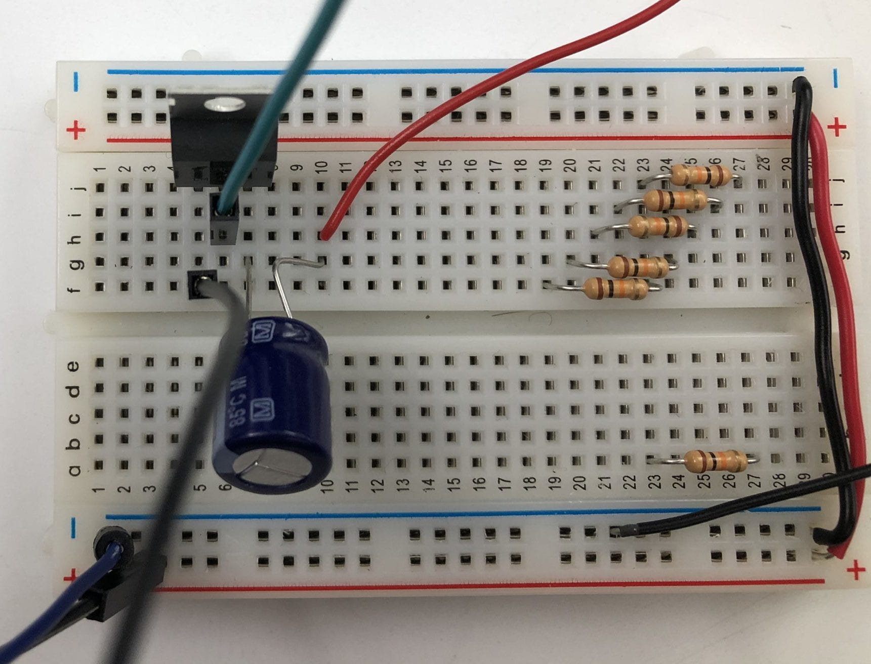
Arnab Chakravarty, ITP Resident, helped me to figure out the amiplification of the sound for the final installation.  We used the following schematic for guidance. 
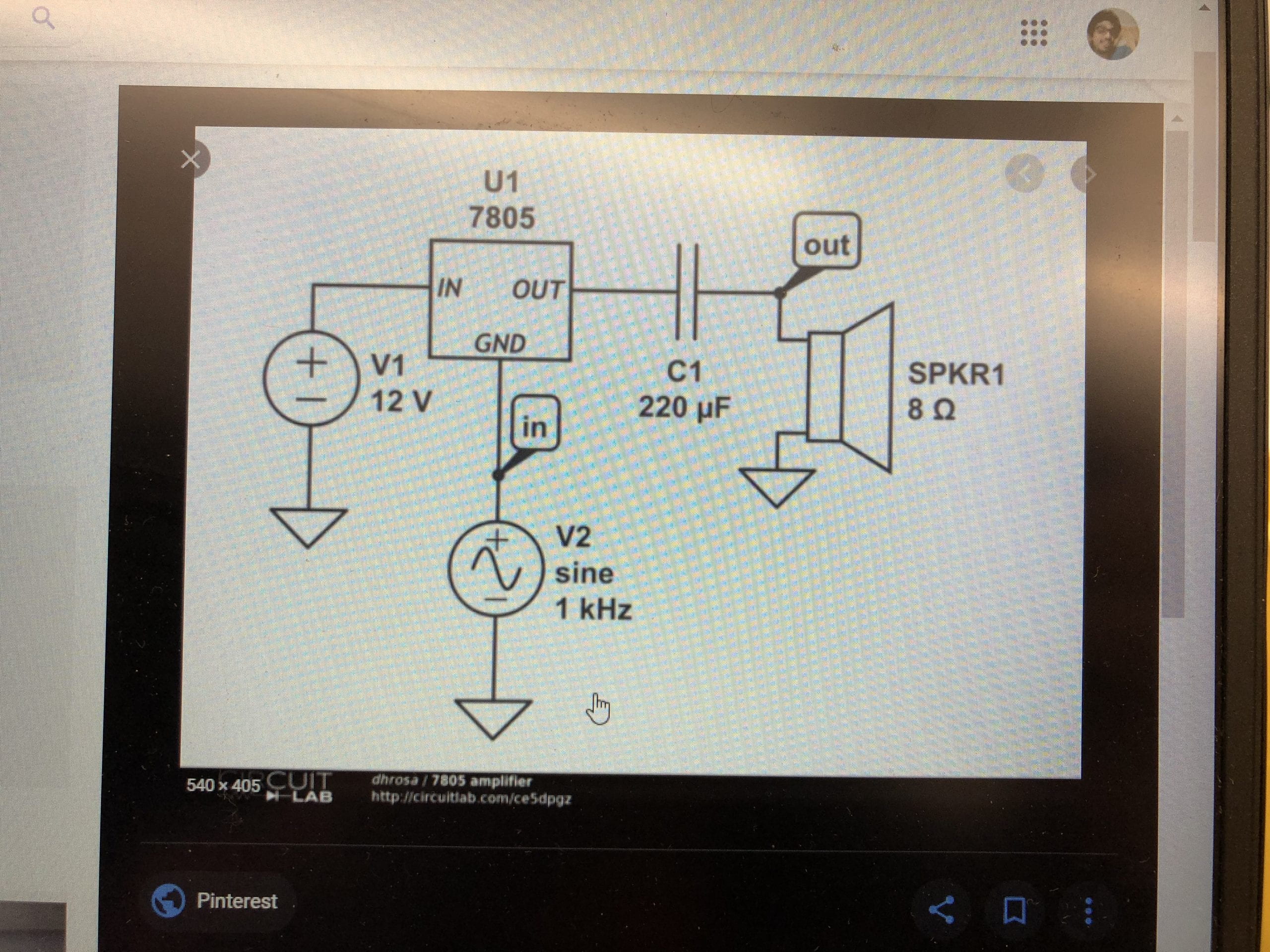
Draft Schematic

breadboard


Final Fabrications:

After measuring the diameters of the speakers, I created the layout in Illustrator then cut the mat board using the laser cutter.  The speakers were glued down with hot glue.  The bottom center speaker (small) was not connected to the circuit as the backing detached from the speaker. 

Code:

The p5.js code and sketch are located here


Next Iteration:

  • I will look into adding a 555 timer IC and will consider finding one from any item that has a blinking light on it.  (Recycle)
  • I’ve considered adding digital potentiometer in order to add another effect to the sound by controlling the volume with the digital pot.  
  • Experiment more with programming of external speakers to play with different programming
    • Look into having a different set-up of speakers 
      • Maybe on the sides while there is a screen at the end that has the P5 projections?

Questions: 

      • How do I test the speakers to find out their wattage and ohms required.  

PComp/ICM Week 14: Speaker Matrix (Final Project) Part 1.

Below is a brief introduction to my final Physical Computing and Intro to Computation Media final project.  There will be a full post coming in the next few days with detailed process documentation. 

Part 1.

This particular project started out relatively far from where it ended.  It started with using old sex toys to create a version of Operation followed by the first iteration of the speaker matrix.  Initially, I was hoping to create an interactive textile using the speakers from old and unused headphones, mainly Apple Earpods (corded).  I loved the idea of an interaction close to the body for the wearer and one for the audience, equally close to the wearer as well.  The textile would either have the speaker facing inward to inform the wearer of  how close someone thing or someone is to their body through use of the sound vibrations.   I realized that the vibrations were to subtle to accomplish this as it stands.  The other option of having the speakers face outward offered a different, yet close, interaction for those around.  The speaker were quite low and would require the some close encounters.  After experimenting with the speakers and continuing to think about the textile, I decided to go in a completely different direction. 

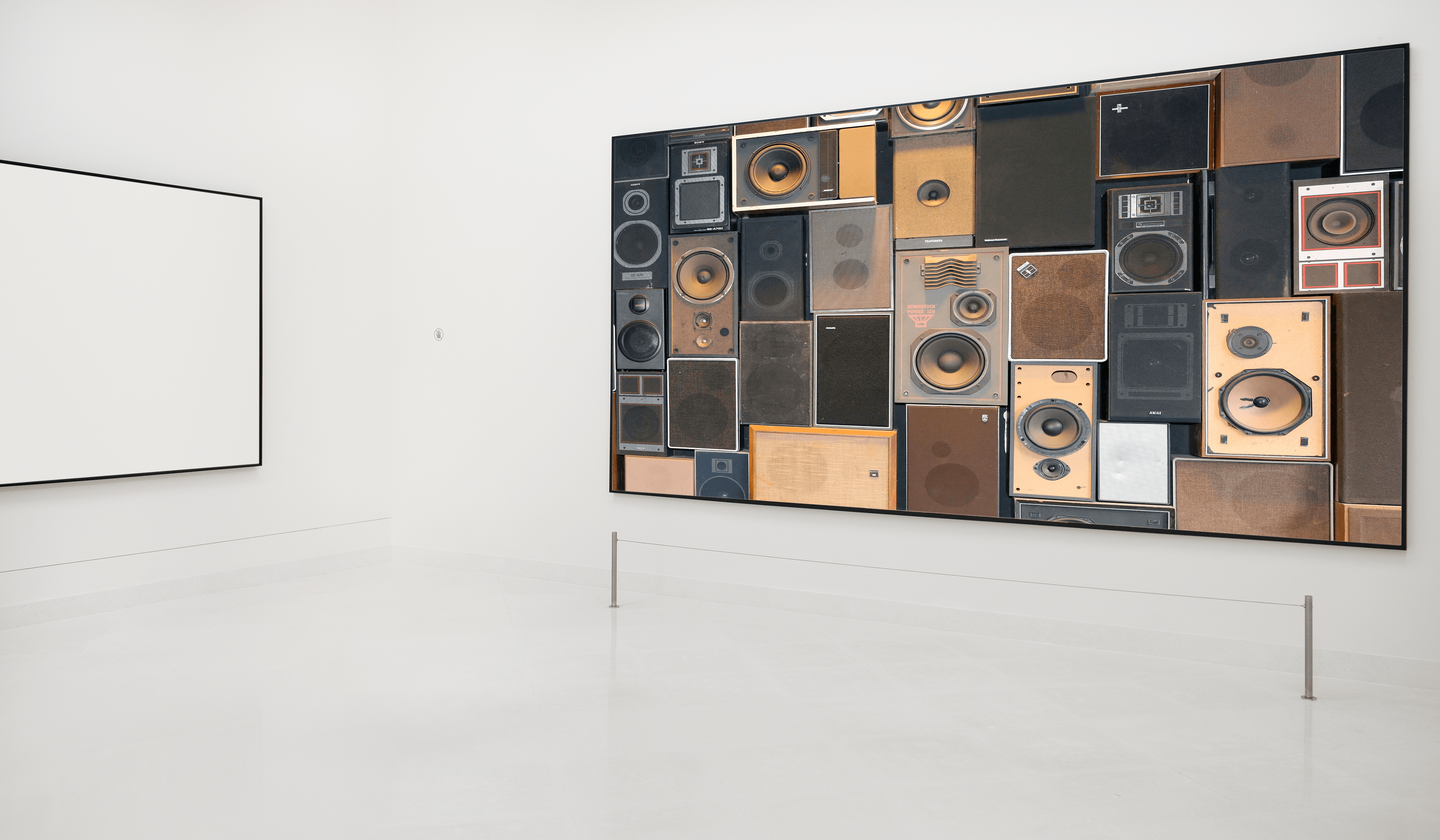
Speaker Matrix MockUp

I wanted to create something that brought joy to myself and others.  Above is an approximation of what I saw in my mind.   Here we have a wall full of salvaged speakers inside a white gallery space.  Upon encountering this room, one would hear the sound of a slow and barely recognizable song.  If the guest chose to continue into the room further, the playback speed would increase so that they might start to pick up on the name of the song.  My hope is that their intrigue into what was really happening would bring them to a few feet in front of the wall, initiating the piece’s dance party!

The dance party will feature club lighting, a disco ball and maybe some fun videos.  With this piece, I wanted to bring someone out of their current state and into joy.  Who doesn’t love a fun dance party?

There is opportunity for other interesting interactions between guests, besides dancing.  If someone enters the room while another guest is in the dance party area, would the piece revert to the bright white room and slowed down some?  How would that, supposed intruder feel and act?  Would they run to the front and join them or flee to another room?  

For this iteration, I have created a small scale mock-up to test the code and experiment with the components and have provided the following video. 

For a full view of the image and to play with controlling the playback rate yourself, here is a full-screen version.  The full p5.js code can be found here.  The Arduino code can be found here

In part 2 I will go through my process, inspiration and challenges as well as provide more technical details and resources.

12/15/2020 UPDATE:
I have successfully added PoseNet detection to the final code.  Now you are able to control the playback rate of the song, trigger the dance part and move the speaker output between speakers with your body.  The code will calculate the distance between your shoulder points to tell how far you are from the screen.   The code can be found here.

PComp Week 11: Project 3 (Operation and Sound Matrix)

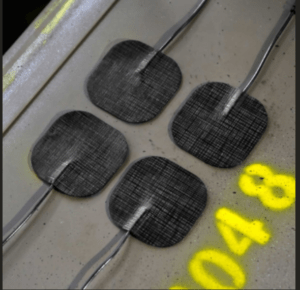
For the third and final project, I am going to focus on utilizing discarded tech.  My original proposal (seen below), ties together  final projects for both ICM and Cybernetics of Sex.  For this project, I proposed taking a set of electro-stimulation toys that I had and re-purposing them into a version of the game Operation.  After testing out the feeling of the electronic current on my hands, I have decided to go in a different direction.  I will, however, breakdown my initial proposal below.  Instead of re-purposing old sex toys, I will focus on re-purposing something I am sure we all either have on hand or have thrown away: headphones. 

I propose creating a swatch of fabric where the speakers from headphone will be attached.  I will use a sensor (most likely a photo sensor) to send a message to the Arduino which will then produce a sound in the speaker.  I envision a garment covered in these speakers and sensors where, as someone passes by, the speakers will emit a sound out of the speaker closest to the passerby.  This idea was  influenced by Daniel Rozin’s mechanical mirror work.  What if instead of a mechanical reaction, there was a sound reaction as someone moved in front of the sensor?  This is what I want to explore.   

Recycled Operation:

Operation

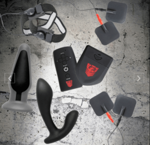
This project will utilize retired sex toys from my own collection to create an interactive game of Operation.  I will use the mechanisms from these toys to create a wearable device (glove, bracelet or rings) that will shock the wearer as they try to harvest the organs without touching the perimeter of the cavity.  The game will be built in p5.js using the Handpose library (ML5), as well as a laptop camera, to detect the parts of the hand.  The user will wearer this device while playing the game.  When the hand reaches the boundary of the cavity, a signal will be sent to from the Arduino to the device which will shot the wearer in the area designated by the p5 sketch. 

E-Stim pads

E-Stim Sex Toy Kit Photo

In addition to the fabrication and safety concerns that are present when working with shocking someone, there are also sanitary concerns due to the use of previously used sex toys.   For this mock up, there is less concern as I will be the only user.  However, this is a concern if I was to involve others in the process.  In my project for Cybernetics of Sex, I do plan on researching ways of sanitizing these toys for reuse as well as any regulations that might pose an issue in scaling this project. 

During the project presentation, there were concerns with safety, as noted above, as well as use.  Would someone want to get shocked?  How would the user gauge if the shock will be tolerable enough to continue to play?  It was also suggested to look at using other actuators (servo motor perhaps) instead of shocking someone.   Also, there is the challenge of building a 3D game within a 2D program.  This idea lends itself more to virtual reality. 

As noted above, I have decided to develop this project o paper for my Cybernetics of Sex class and to, instead, build the following sound project. 

Wearable Sound Matrix:

Currently, I have 5 pairs of Apple ear-pods that are no longer useful in their current state.  I will be disassembling them to make a wearable sound array. 

While doing research for this project, I found iFixIt to be very helpful in tearing down the ear pods.

This project will require researching how to take headphones apart without damaging the components, what are they made of and how to reuse them.  As I am interested in the reuse of all components of the headphones, I will also research the use of not just the speakers but of the other components that make of the headphones.  My goal is to use all the parts in some fashion.  If not, I will figure out how to best recycle the items as well. 

I am excited by the research and experimentation that this project requires and look forward to seeing it come to fruition. 


Week 10 PComp: Motor Labs

Lab 1: Using a Transistor to Control High Current Loads with an Arduino

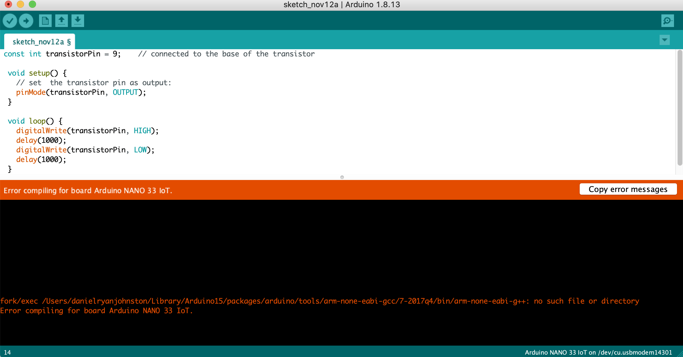
Since I had to wipe my palmtop earlier in the week, I had to reinstall the Arduino IDE as well as the Nano 33 IoT board.
I was receiving the following error: 

Arduino Error

After downloading the drivers and making sure everything I could do was done, I witched to Adafruit Metro and was able to get it to work.


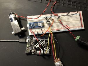
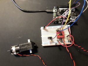
Motor Lab 1 Breadboard Setup

I   was able to get the motor up and running successfully along with the use of the potentiometer.

Lab 2: DC Motor Control Using an H-Bridge
That was also successful. 

Motor Lab 2 Breadboard Setup

Might explore using a motor in 3rd project depending on what I can figure out and/or find on the floor for free.

Lab 3: Controlling a Stepper Motor With an H-Bridge

Stepper Datasheet

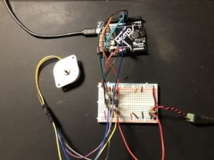
Motor Lab 3 Breadboard Setup

I was able to get the stepper motor to work using the code in the example. Unfortunately, my motor’s data sheet does not have a listing for steps per revolution. I believe this caused some issues as the stepping was not consistent and stopped several times.


Project 2: Soft Game Controller

This post combines week 8’s project update along with week 9’s final project posting. 

For preliminary documentation, please see week 7’s post here
All the code, both P5 and Arduino, are located here in the P5.js sketch. 

As a refresher, the goal of my project was to create a plush game controller utilizing a button and 2 variable resistors.  In the last update, I showed the game (P5.js) sketch which was mostly complete.  I did fix a few items but it mostly stayed that same; get the ball in the box then a new ball and box appear for you to try again.  I next began with testing combinations of steel and sheep’s wool.

Variable Resistor Tests:

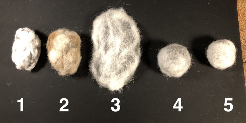
I created 5 different versions of the resistor which all had varying results.  The first was a combination of cotton and steel wool as I had not yet received the sheep’s wool.  This particular combination had very little connectivity when tested.  I was not able to felt it properly either which could have had a effect.

The next 4 were all steel and natural wool.  Each offered promising qualities but ultimately they did not offer enough of a variable in regards to their resistance.  The final two (felted balls) had 0 resistance but they were nicely felted and I do hope use them for something in the future.  

Display of 5 Variable Resistor tests

All 5 tests use Homax Extra Fine #000.

  1. Cotton and steel wool.
    1. Ratio: 4-1 Cotton to Steel Wool
    2. Process: hand felted (compacted and worked by hand). 
    3. Resistance Range: 0 or 1.  Depending on where the alligator clips were placed I received either no resistance or 100% resistance. 
  2. Sheep’s wool and steel wool.
    1. Ratio: 4-1 Sheep’s Wool to Steel Wool
    2. Process: hand felted (compacted and worked by hand). 
    3. Resistance Range: 0-500
    4. Comments: See video below for resister demo.  Since this one was washed, it did rust.  This caused the rust to come off as you squeezed it.
  3. Sheep’s wool and steel wool (Flat)
    1. Ratio: 8 thin layers of Sheep’s wool to 7 layers of thin steel wool.  
    2. Process: Started with very thin layers of each.  Felted each layer to the other to create the shape. 
    3. Resistance Range:  0 resistance
    4. Comments: I might try washing/drying this test to see how that might change it. 
  4. Sheep’s wool and steel wool. (Loose Ball)
    1. Ratio: 1 to 1 (3 layers of each)
    2. Process: started with ball of steel wool in the middle then added layer of sheep’s wool followed by steel wool, etc.  Felting each time. 
    3. Resistance Range: 0 resistance
  5. Sheep’s wool and steel wool. (Denser Ball)
    1. Ratio: 2 to 1 Sheep’s to steel wool
    2. Process: started with ball of steel wool in the middle then added layer of sheep’s wool followed by steel wool, etc.  
    3. Resistance Range: 0 Resistance
    4. Comments:  I used thicker layers of sheep’s wool to steel wool but did a tighter felting. 

Here is a video of my second test which did provide the variable resistance but it was not consistent throughout the ball. 

Before switching to a different sensor, I was able to test this same  wool resister with the P5.js sketch.  I found that there was no resistance;  x of ball stayed stable but once added resistance the input of the x was extreme.

At the recommendation of ITP Resident August Luhrs, I was able to get some advise from former ITP graduate Hannah Tardie.  Hannah offered a wealth of recommendations and resources for creating soft interfaces.  I am grateful to both August and Hannah for their help. 

After a few more test with the steel and natural wool, I decided to switch to a different material.  I decided that this method was the most sustainably in regards to it’s fiber content.  In order to cut down on any unnecessary waste, I chose to utilize a recommendation of Hannah, neoprene fabric pressure sensor.   The new pressure sensors were based on this tutorial from KOBAKANT. I will find a use for those items at a later date though. 

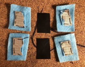
I used scrap fabrics (felt, conductive fabric, neoprene and Velostat) that  I had on hand. 

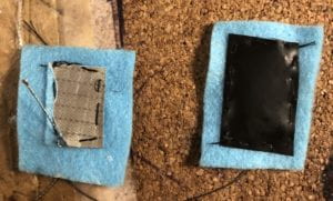
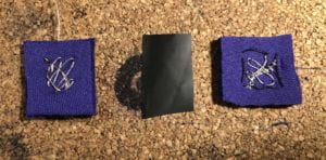
Fabric Pressure Sensor 1 Open
Felt with conductive fabric plus Velostat.

Fabric Pressure Sensor 1 Open 2

Fabric Pressure Sensor 2 Open
Neoprene, Velostat, Adafruit Medium conductive thread.


I created two versions of these sensors:

1 – Conductive fabric bonded to felt (left over from ITP Camp 2018 workshop),  Adafruit medium conductive 3 ply thread and Kelostat.  This combination kept getting reading on the Arduino of 1019-1023.  (It took me awhile to figure out but these readings were incorrect.  There was an error with the construction as well as with the Gemma that effected the readings.  In the end I used this set.)

2 – neoprene (bonded to leather), steel thread (confirm exact type) and Velostat.  Meter readings from 0-150.  This set was successful in combination with the P5 sketch. 

Code: Nano to Gemma

Since the Nano 33 IoT needed to be in a breadboard, I chose to switch to one of the Adafruit Gemma MO’s that I had around.   August was able to offer assistance figuring out the necessary code changes for setup for Adafruit GemmaMO.  In the end all I needed to add was pinMode(buttonPin, INPUT) in order for the Gemma to read the digital pin.  In the code for the Nano, this wasn’t needed. 

Schematic (Nano 33 IoT and Adafruit Gemmo MO)

INSERT
Schematic of circuit
Nano and Gemma MO

Finish Line:

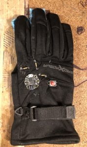
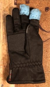
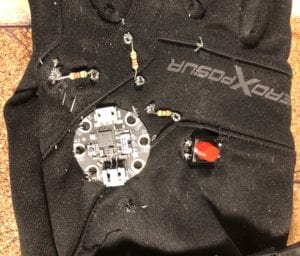
Once the components were all attached to the glove, it was time to test it with P5.js.   The first test resulted in a few errors.  There were a few short circuits happening due to the ends of the conductive threads touching in a few spots.  Resolving those issues took some time but I finally got them worked out. 

Glove Front Glove Back Closeup of Components

How to play:

  • Goal: Get the ball into the box.
  • Controls:
    • Press your pointer finger on the table to control the the ball along the X-axis.
    • Press your middle finger on the table to control the ball along the Y-axis. 
    • After the ball has disappeared and the box is red, press the button to try again. 

Challenge:

The biggest challenge that I had and did not plan on, was figuring out the path tracing for the conductive threads.  Since I was not using wires, I needed to make sure that I did not short circuit any of my connections.  Unfortunately, this was a problem for a bit but I was able to figure it out eventually.

Reflection:

I would like to fix/upgrade the following when I chose to take this project further:

  • The game needs to be developed more to include a score keeper as well as a redesign of the look. 
  • I would still like to try creating the plushy variable resistor as originally planned.
  • If P5 can support this, utilizing Blu-tooth, as well as a compatible micro controller, I would like to be able to have the device be remote.