Final Project Documentation Part 1.
Initial Project Blog
Part 2
Inspiration:
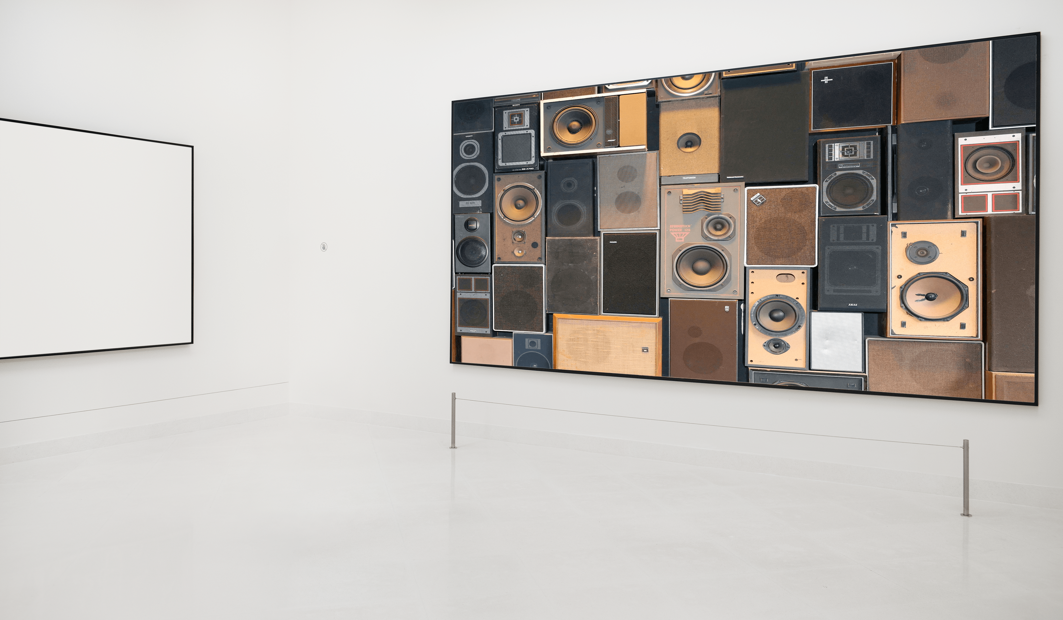
After my initial idea of utilizing retired sex toys for a game of Operation, I found inspiration in Daniel Rozin’s Mirror pieces as well as the following:
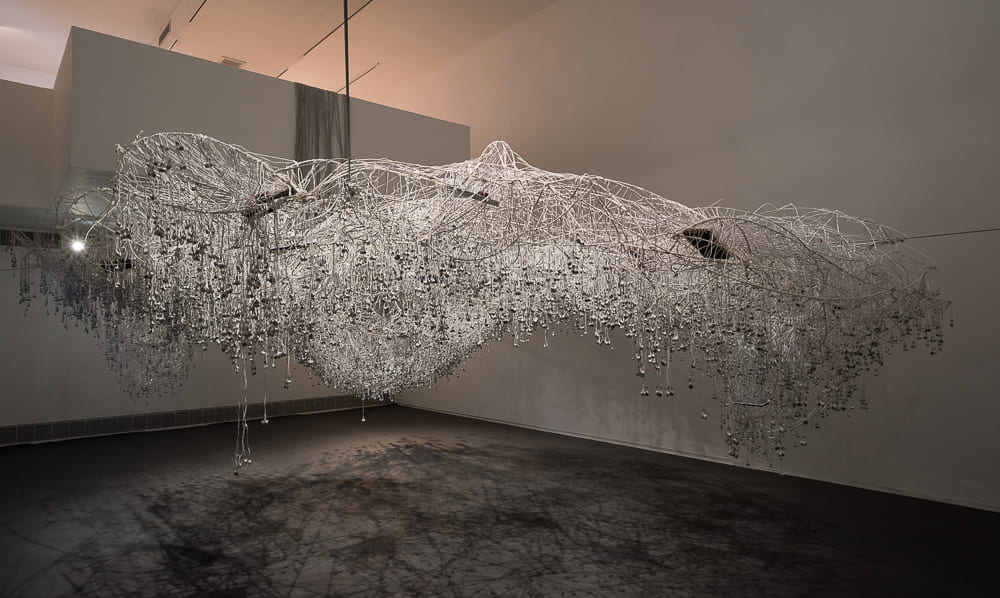
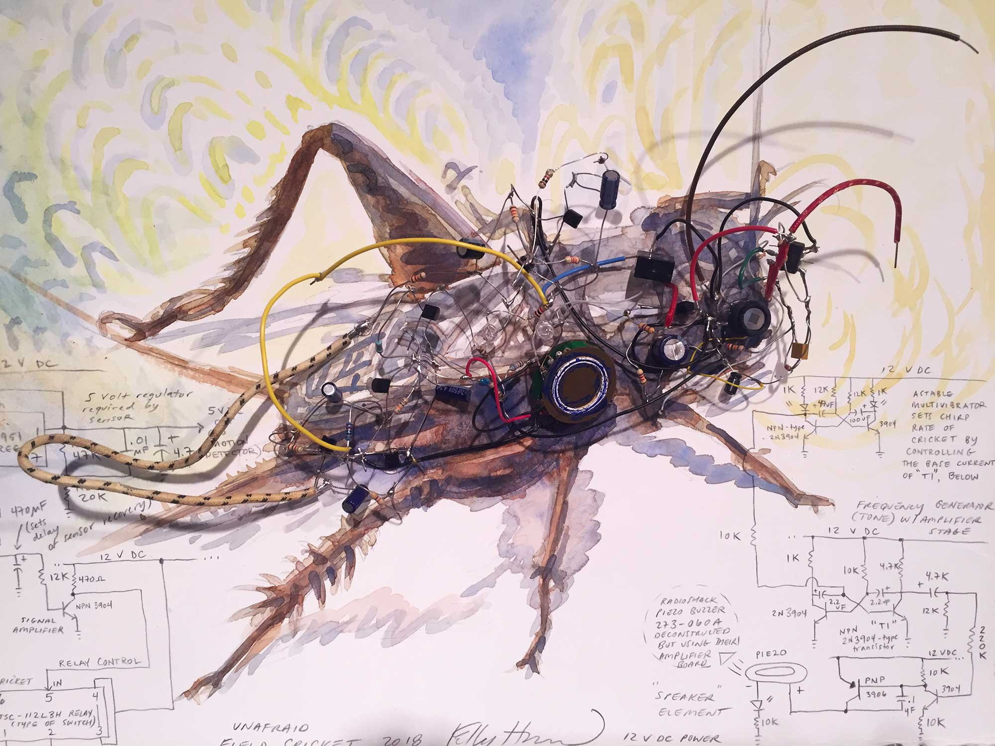

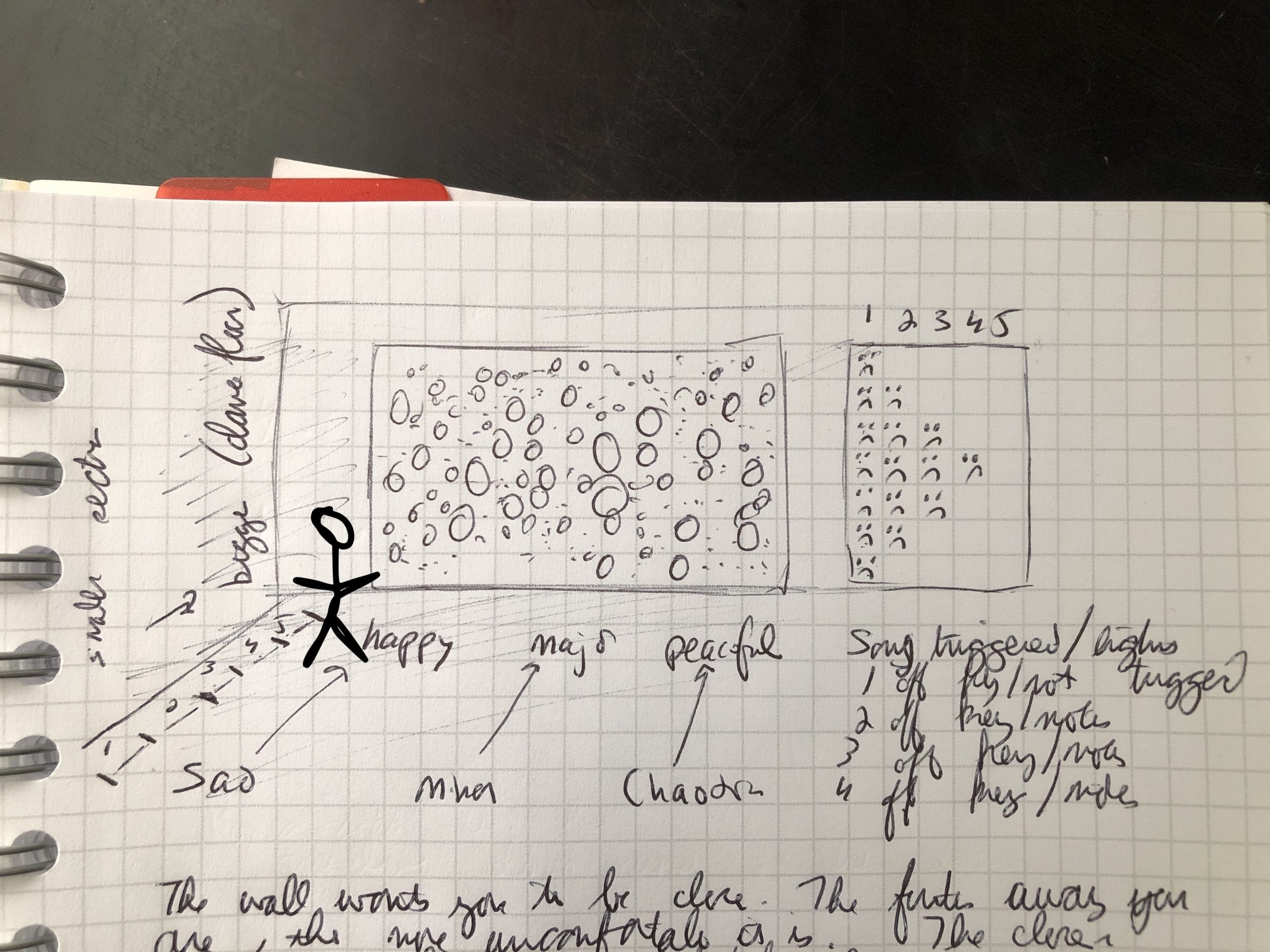
Once I had a good sense of where I was going, I moved forward with experimentation.
Tear-down of Headphones:
I used the following list of headphones. The Apple earpods were old ones from my apartment and the others were found for free on the junk shelf at ITP.
- Headphones/Speakers:
- 5 sets of Apple Headphones
- 1 pair of metal headphone of unknown origin
- 1 pair of Sony headphones
- 1 pair of Panasonic XBS headphones
- 1 pair of Insignia headphone
Referring to iFixit’s guide to Apple EarPods, I began but tearing down the sets I had on hand. I used an Xacto knife to get the casing off, making sure not to cut the wires before I was able to test their connections.
Working with Speakers:
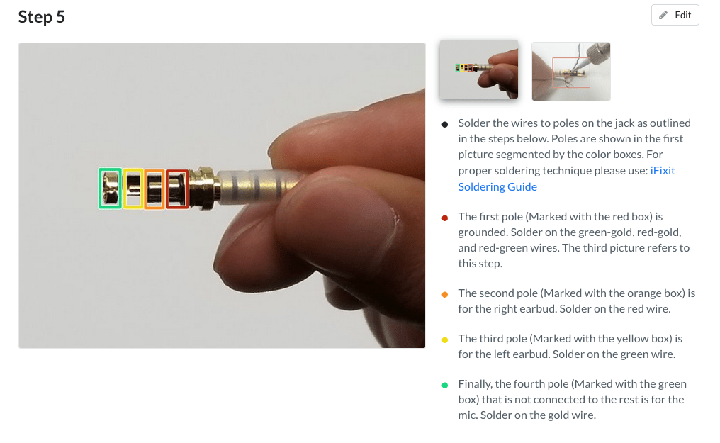
The above page was very helpful in figuring out the positive and negative wires for the speakers. This is from iFixit’s site and can be found here. All the speakers used a similar color coding for the wires. The in wires were all either red or either with bronze wires. The ground wires were all bronze. In order to test that I was assigning the wires correctly, I used the following site along with a multi-meter. This was specific to the Apple headphones but was transferable to the other sets as well.
-
- GND – Red-Gold and Green-Gold Wires
- Connection labeled BB0 on the speakers
- Voltage – Gold and Green
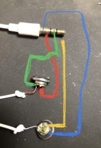
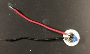
I did run into a challenge when soldering on the new wires (see below) where the soldering points would detach from the speaker casing. I was able to reattach it using hot glue but only for the one speaker. The second speaker shown below I have not been able to reattach that connection. Later, when building the final piece, I covered the connections in hot glue in order to protect them.
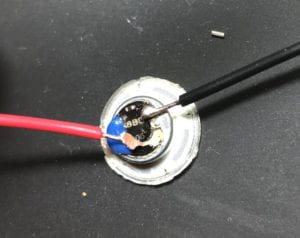
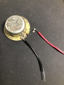
In the end, tear-down went as expected. Technology is not made to be taken apart. I used a small knife and pliers in order to get the casings off. I had to make sure not to tear a whole into the paper cones of the speakers when I was prying them apart.
Building the Circuit:
For all components, I started with one and scaled up. At the very beginning, I started with 1 Nano 33 IoT, 1 LED and 1 Photo Resistor. This lab from class was helpful in beginning this project.
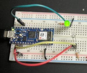
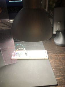
Next, I moved on to configuring the lighting rages in preparation for coding the interaction (varying distances from sensor would trigger different sounds and images). Using a 40W LED light bulb, I measured the following
- Sensor Range:
- With a 40 W light bulb 12 inches away from the sensor
- Bottom: 0-10
- Top: 35-50
- 40w bulb 12 inches away from sensor
- Bottom: 5-15
- Top: 70-110
- 40w bulb 6 inches away from sensor
- Bottom: 40-60
- Top: 430-510
- With a 40 W light bulb 12 inches away from the sensor
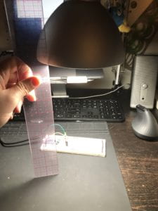
5 LEDs and 5 Photo Sensor: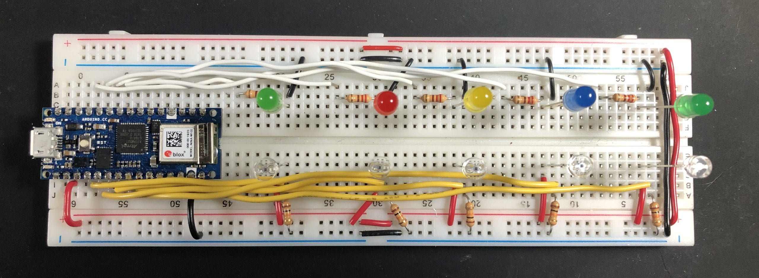
Breadboard Circuit 5 LEDS and 5 Photo Sensors
Adding Speaker to Circuit:
Testing Speaker:
I think these have a resistor built in.
Resistance: .037
* Used multimeter on tone to see if there is a connection between the two
De-solder the connection then add new wires for testing
* With the new wires: .039
* Show picture of new wires
* Caution
* When soldering the new connections onto the speaker, I think the iron was too hot and the tracing lifted up on the rest of the case. I will have to encase the backing with hot glue to prevent it from coming apart.
* Research:
* Driver: https://www.quora.com/What-is-the-driver-specification-of-apple-earpods?share=1
* Patent:
* https://www.patentlyapple.com/patently-apple/2013/01/apples-patent-for-their-revolutionary-earpods-comes-to-light.html
* http://patft.uspto.gov/netacgi/nph-Parser?Sect1=PTO2&Sect2=HITOFF&p=1&u=%2Fnetahtml%2FPTO%2Fsearch-bool.html&r=4&f=G&l=50&co1=AND&d=PTXT&s1=175588&s2=apple&OS=175588+AND+apple&RS=175588+AND+apple
Once the LEDS and photo resisters worked well together, I added a speaker. I used https://itp.nyu.edu/physcomp/labs/labs-arduino-digital-and-analog/tone-output-using-an-arduino/ for guidance setting up the circuit.
-
- 4 ohm 3 W speaker (adafruit)
- INSERT MEDIA
- Resources for Sound:
- Adding more Speakers
- Once I had the code set for one speaker, I moved up to include additional ones. Ultimately having 12 speakers in total.
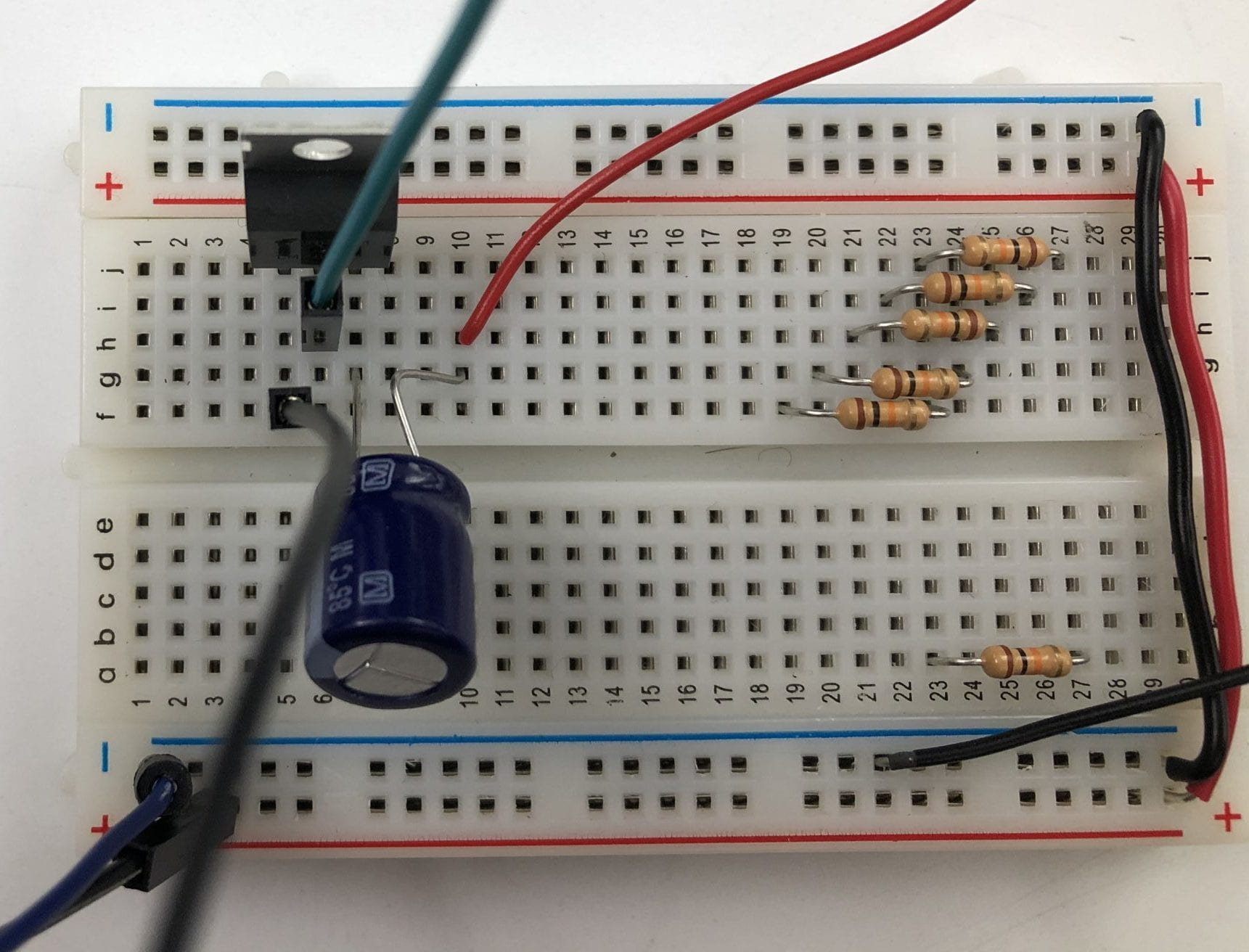
- Arnab, a resident, helped me with adding the 220µƒ capacitors to the circuit.
Schematic:
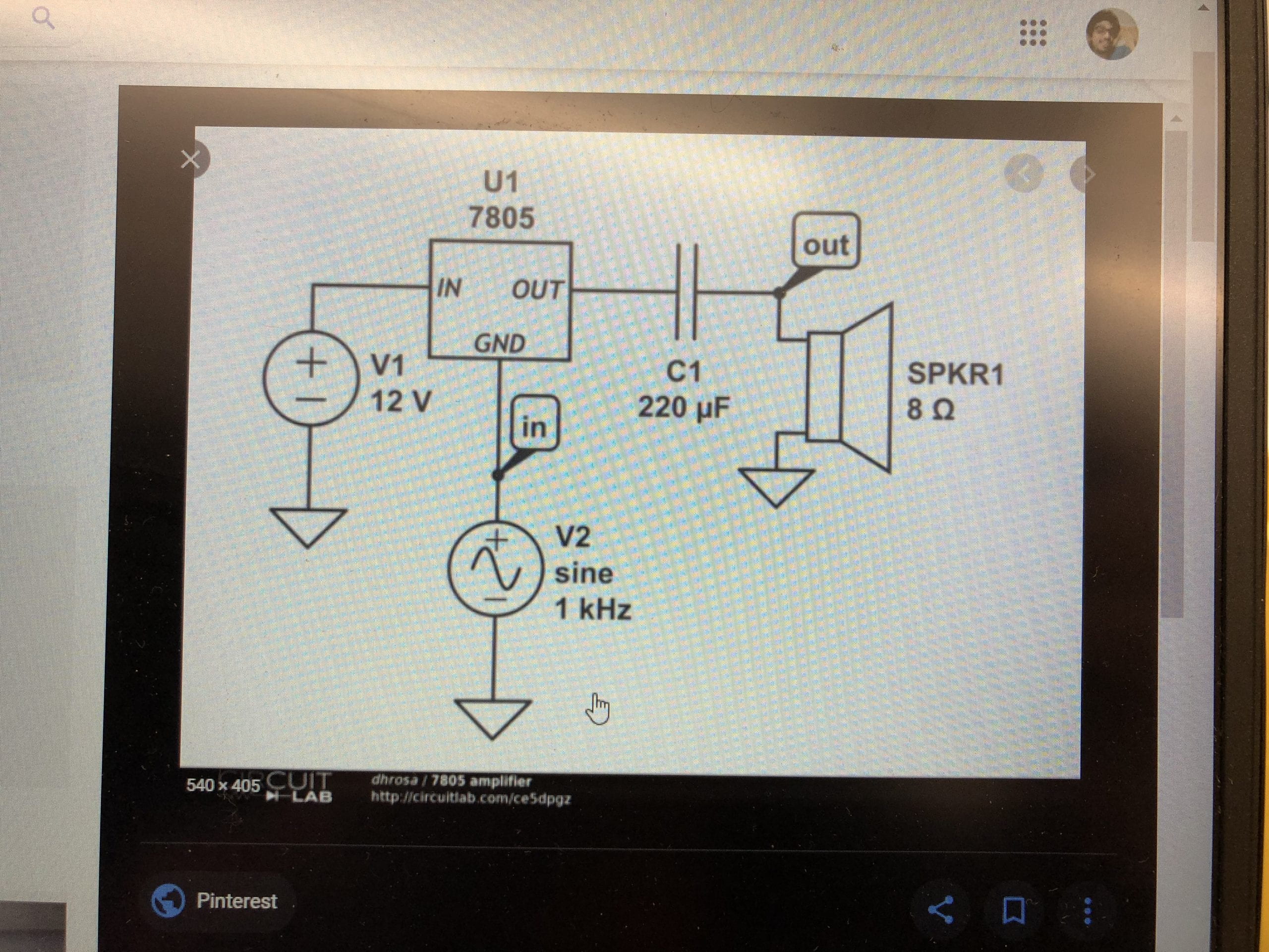
Arnab Chakravarty, ITP Resident, helped me to figure out the amiplification of the sound for the final installation. We used the following schematic for guidance.
Final Fabrications:
After measuring the diameters of the speakers, I created the layout in Illustrator then cut the mat board using the laser cutter. The speakers were glued down with hot glue. The bottom center speaker (small) was not connected to the circuit as the backing detached from the speaker.
Code:
The p5.js code and sketch are located here.
Next Iteration:
- I will look into adding a 555 timer IC and will consider finding one from any item that has a blinking light on it. (Recycle)
- I’ve considered adding digital potentiometer in order to add another effect to the sound by controlling the volume with the digital pot.
- Experiment more with programming of external speakers to play with different programming
- Look into having a different set-up of speakers
- Maybe on the sides while there is a screen at the end that has the P5 projections?
- Look into having a different set-up of speakers
Questions:
-
-
- How do I test the speakers to find out their wattage and ohms required.
-


