I’d like to start out with the final project in this week’s selections of reading and labs:
Creative Switches in Series
Inspiration:
Like the majority of the world, masks and sanitizer have become necessary additions to our daily routine. What better everyday activity to use as inspiration than one we all wish wasn’t. I decided to build this circuit around an instance of coming home from a walk.
Process:

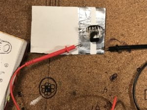
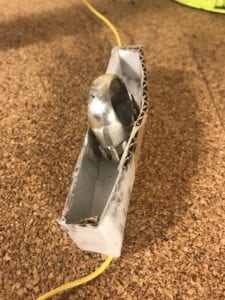
After I had the basic idea mapped out, I started building the ring switch. I first had to make sure the ring was going to be able to carry a current, which luckily it did. Then came the actual switch. Initially, I was going to have the the action required for the switch be placing the ring on a flat surface with the two conductive contact points on either side (see picture below). Unfortunately, the connection wasn’t strong enough so I decided to create a case to put the ring into which would close that switch.
Next, I worked on the mask switch.
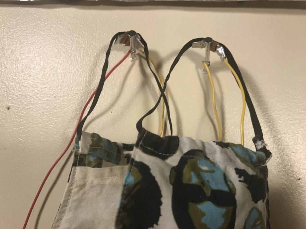
Since the nails used were not conductive, I needed to wrap them with aluminum foil so that they could be part of the switch. Next I strung a wire in the pocket of the mask, connecting the two ear holds. I used aluminum foil and copper tape to attach the wire to the elastic. The copper tape was necessary as the aluminum duct tape was not conductive on its sticky side, unlike the copper tape. Using the copper allowed me to wrap the connections without needing to use a separate glue.
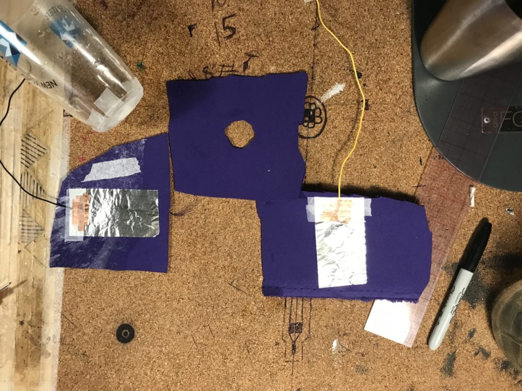
With the two other switches working, I needed to figure out how best to create the cup pressure sensor. I had created a fabric pressure sensor once before so I had a basic idea of how to proceed. The challenge was be making sure the switch didn’t close before I poured the water into the cup. I experimented with a few different cups and settled on a plastic one. Ideally, I would have used a cup with a completely flat bottom but all the plastic cups I had on hand had curved bottoms.
For the fabric switch, I initially made a 2 and 3/4 inch diameter circle in the neoprene which separated the two conductive sides of the switch. Because the opening was so big, the switch closed before I could pour any water into the cup. I then tired cutting a new piece of neoprene with a smaller opening, 7/8th of an inch across. This size opening allowed the switch to stay open while waiting for the water to be poured, but did not close the switch once filled. This was because the bottom of the cup was curved up which did not place enough pressure on the top layer of fabric even though the cup was full. To fix this, I taped a small ball of paper onto the bottom of the cup which, once the cup was full, pressed down through the center hole closing the switch.
Completing the Circuit
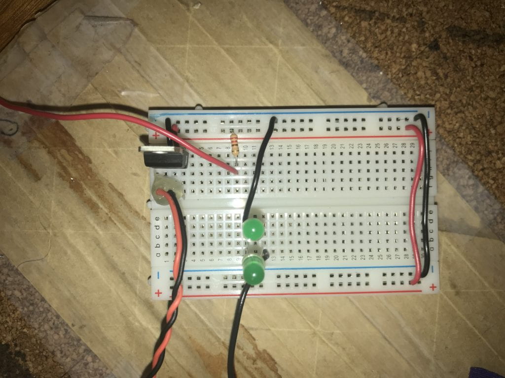
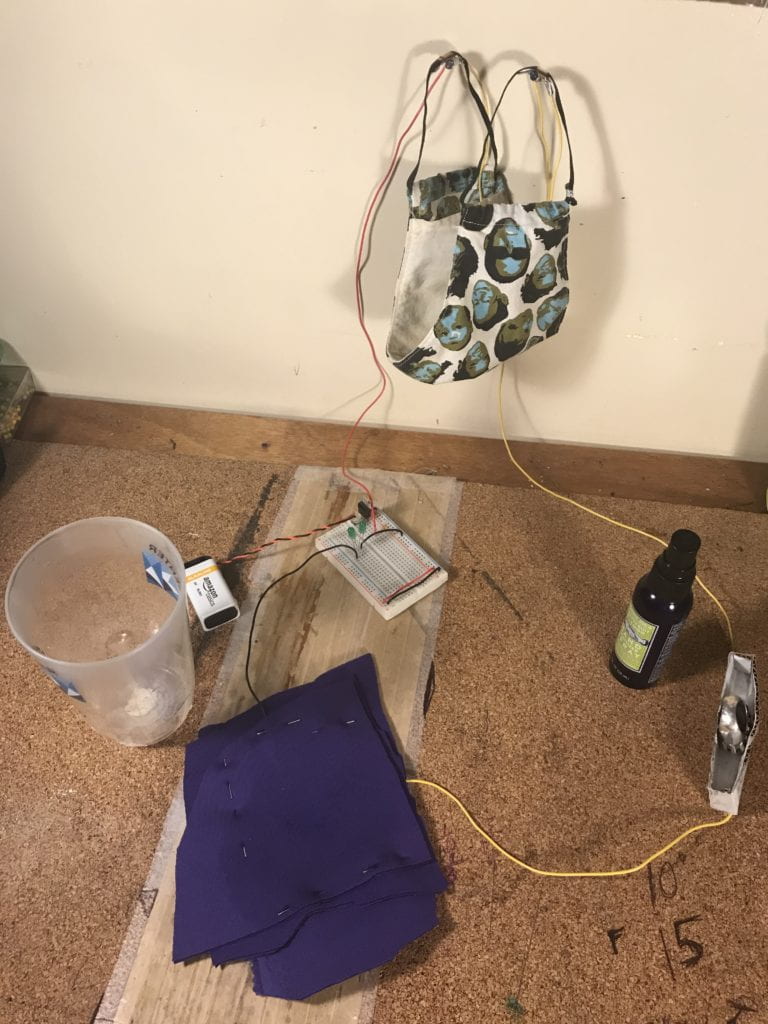
The final step was to connect the series of switches to the power via the breadboard. I did not need to modify the setup much as I had just created a circuit with an LED and a potentiometer prior to working on this lab. Here is a closer picture of my board layout.
Switch Materials:
Switch #1: The Mask
- Cotton mask with elastic
- Aluminum foil
- Copper tape
- (2) Nails wrapped in aluminum foil
- Wires
Switch #2: The Ring Box
- Silver Ring
- Cardboard
- Aluminum Foil
- Aluminum Duct Tape
- Copper Tape
- Scotch Tape
- Wires
Switch #3: Glass of Water
- (1) Plastic Cup
- Neoprene
- Aluminum Duct Tape
- Copper Tape
- Wire
- Dress Pins
- Water
- Paper
- Scotch Tape
Lab 1: Components
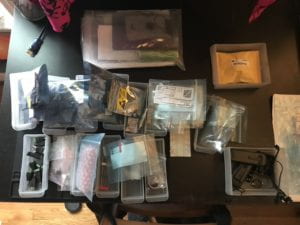
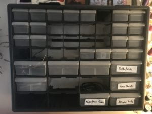
I found this lab to be very helpful as it allowed me to organize my supplies and equipment while getting a better handle on exaclty what I had on hand. I now have a much better understanding of the components as well as confidence in being able to identify individual components.
Here are a few pictures of my organizing progress:
Lab 2: Breadboard
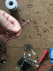
I decided to build the setup in this lab as I wasn’t entirely sure if this was a lab to report something or just an informative lab. I did, however, get to practice soldering headers to a 9V batter snap which came in handy for lab 3.
Lab: Electronics
A few years back, I bought a DT-9205B Digital Mulitmeter but did not get too much use out of it. I learned in the lab just how different multimeters can be. Learning about my multimeter was insightful. Unfortunately, the handbook for this particular meter was not entirely accurate when it came to identifying the icons on the front. Through comparing the meetings shown in the lab and in the videos, I was able to figure out how my mulitmeter works and was able to take all the necessary readings for this lab.
Lastly, here are a few questions I had from the readings:
- When organizing electrical components, are there any precautions we need to take in regards to static? And if so, which components do we need to be most concerned with?
- Can we discuss more about pull-up and pull-down resistors and how they differ (type, location in circuit, etc.)?
- Please explain relationship further the relationships happening in the equation Watts = Volts * Amps
- When would we need to use the variable bench power supply ?
- How does RC differ from DC/AC and what accommodations do we need to make in a circuit to use RC?
- What is a voltage divider circuit?
- With photocells going out of fashion due to their toxicity, are phototransistors equivalent? Will these take the place completely of photocells and what do we need to know when using phototransistors in place of photocells?
- Can you provide an example of when we would use a rotary encoder in a project?