In our second recitation, we received our own Arduino and soldering tool kit; then, we had an individual hands-on exploration with Arduino. We had our first experience connecting some relatively more complex circuits and had a glimpse of the joy of working with electricity and Arduino.
Circuit 1: Fade
In this circuit, the Arduino coding controls the LED to fade on and off with a certain rhythm. AnalogWrite ( ) is used in the coding part. Along with pulse width modulation (PWM), this circuit created the fading effect with LED.
Components:
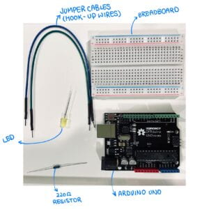
- Arduino UNO board: It creates a platform to merge the hardware and software in electronic prototyping easily;
- Breadboard: It has many holes that allow inserting circuits easily;
- Jumper cables: It is a pathway to allow normal flow of electricity;
- LED: It lights when there is electric current flow through it;
- 220-ohm resistor: it resists the electric flow and controls the flow of current. Here, it prevents the LED from burning because the 5 volts of power exceeds the maximum voltage of the LED.
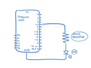
Schematic:
My Work:
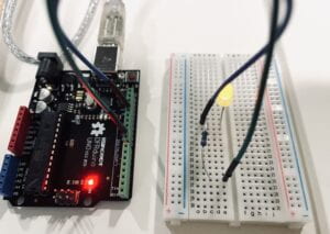
This is my Arduino hardware circuit connection:
Here is my code:
int ledPin = 9;    // LED connected to digital pin 9

void setup() {
  // nothing happens in setup
}

void loop() {
  // fade in from min to max in increments of 5 points:
  for (int fadeValue = 0 ; fadeValue <= 255; fadeValue += 5) {
    // sets the value (range from 0 to 255):
    analogWrite(ledPin, fadeValue);
    // wait for 30 milliseconds to see the dimming effect
    delay(30);
  }

  // fade out from max to min in increments of 5 points:
  for (int fadeValue = 255 ; fadeValue >= 0; fadeValue -= 5) {
    // sets the value (range from 0 to 255):
    analogWrite(ledPin, fadeValue);
    // wait for 30 milliseconds to see the dimming effect
    delay(30);
  }
}
Here is my final work of Circuit 1:
Reflection:
The working process of Circuit 1 went on very well. With the help of the experience connecting circuits from the previous class, it was relatively simple to connect LED and 220-ohm resistor to the Arduino board correctly. The only problem I encountered was I did not understand the coding part as the code was the existed example from the Arduino app. I spent some time making sense of the coding language, but I was stuck with the part controlling the fading effect. I asked one of the fellows, and he suggested I change some of the values in the code to see the purposes of each. As shown in the second video, the LED turned on and off more quickly than the first one as I decreased the “delay” values.
Circuit 2: Tone Melody
This circuit used the tone( ) to play a short melody with the buzzer.
Components:
- Arduino UNO board: It creates a platform to merge the hardware and software in electronic prototyping easily;
- Breadboard: It has many holes that allow inserting circuits easily;
- Jumper cables: It is a pathway to allow normal flow of electricity;
- Buzzer/speaker: It makes noise or toned sounds when electricity flows through.
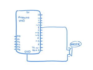
Schematic:
My Work:
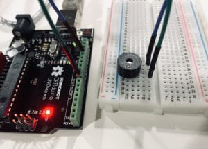
Here is my code:
#include "pitches.h"

// notes in the melody:
int melody[] = {
  NOTE_C4, NOTE_G3, NOTE_G3, NOTE_A3, NOTE_G3, 0, NOTE_B3, NOTE_C4
};

// note durations: 4 = quarter note, 8 = eighth note, etc.:
int noteDurations[] = {
  4, 8, 8, 4, 4, 4, 4, 4
};

void setup() {
  // iterate over the notes of the melody:
  for (int thisNote = 0; thisNote < 8; thisNote++) {

    // to calculate the note duration, take one second divided by the note type.
    //e.g. quarter note = 1000 / 4, eighth note = 1000/8, etc.
    int noteDuration = 1000 / noteDurations[thisNote];
    tone(8, melody[thisNote], noteDuration);

    // to distinguish the notes, set a minimum time between them.
    // the note's duration + 30% seems to work well:
    int pauseBetweenNotes = noteDuration * 1.30;
    delay(pauseBetweenNotes);
    // stop the tone playing:
    noTone(8);
  }
}

void loop() {
  // no need to repeat the melody.
}
Here is my final work of Circuit 2:
Reflection:
Similar to the first circuit, the connection of the second circuit went on very well. I did not encounter any problems with connecting the components and forwarding the code to the Arduino Board. The same issue still existed that I did not understand the code at all. In my experience of coding a melody, I used the series of numbers to represent audio-frequency instead of using this set of fixed tones. I hope we can explain these codes soon in class.
Circuit 3: Speed Game
This circuit aims to create a game that can involve two players. When the game starts, the two players each start clicking on one push-button switch. The serial monitor will record each click, and the one player reaches ten clicks first wins. The corresponding LED will light up when the player wins and make a toned melody with the buzzer in the middle.
Components:
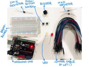
- Arduino UNO board: It creates a platform to merge the hardware and software in electronic prototyping easily;
- Breadboard: It has many holes that allow inserting circuits easily;
- Jumper cables: It is a pathway to allow normal flow of electricity;
- Buzzer/speaker: It makes noise or toned sounds when electricity flows through;
- LED: It lights when there is electric current flow through it;
- 220-ohm resistor: it resists the electric flow and controls the flow of current. Here, it prevents the LED from burning because the 5 volts of power exceeds the maximum voltage of the LED.
- Push-button switch: it interrupts the flow of current within the circuit so that the circuit is reconnected when pushing the button;
- 10-k ohm resistor: it resists the electric flow and controls the flow of current. In this circuit, this resistor is connected to the push-button switch to prevent it from burning.
Schematic:
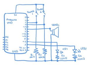
My Work:
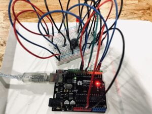
Here is my code:
int buzzerPin = 8;
int button1 = 11;
int button2 = 10;
int led1 = 3;
int led2 = 2;

int goal = 10;
int buttonState1 = LOW;
int previousState1 = LOW;
int buttonState2 = LOW;
int previousState2 = LOW;

int counter1 = 0;
int counter2 = 0;
boolean winner1 = false;
boolean winner2 = false;

// the follow variables are long's because the time, measured in miliseconds,
// will quickly become a bigger number than can be stored in an int.
long time = 0;         // the last time the output pin was toggled
long debounce = 200;   // the debounce time, increase if the output flickers

void setup() {
  // put your setup code here, to run once:
  Serial.begin(9600);
  pinMode(buzzerPin, OUTPUT);
  pinMode(button1, INPUT);
  pinMode(button2, INPUT);
  pinMode(led1, OUTPUT);
  pinMode(led2, OUTPUT);
  Serial.println("******************* RACE THE LED *******************");
  delay(1000);
  Serial.println("READY");
  delay(1000);
  Serial.println("SET");
  delay(1500);
  Serial.println("GO!!!!!!!!!!!!!!!!");

}

void loop() {
  // put your main code here, to run repeatedly:
  buttonState1 = digitalRead(button1);
  buttonState2 = digitalRead(button2);
  //Serial.println(buttonState1);

  //this checks the times player 01 has pressed the button
  if (counter1 < goal && winner2 == false) {
    if (buttonState1 != previousState1 && millis() - time > debounce) {
      if (buttonState1 == HIGH) {
        counter1++;
        Serial.print("player 01:  ");
        Serial.println(counter1);
        time = millis();
      }
    }
    previousState1 = buttonState1;
    if (counter1 == goal && winner2 == false) {
      winner1 = true;
      digitalWrite(led1, HIGH);
      Serial.println("PLAYER 01 WINS");
      playMelody();
    }
  }

  //this checks the times player 02 has pressed the button

  if (counter2 < goal && winner1 == false) {
    if (buttonState2 != previousState2 && millis() - time > debounce) {
      if (buttonState2 == HIGH) {
        counter2++;
        Serial.print("player 02:  ");
        Serial.println(counter2);
        time = millis();
      }
    }
    previousState2 = buttonState2;
    if (counter2 == goal && winner2 == false) {
      winner2 = true;
      digitalWrite(led2, HIGH);
      Serial.println("PLAYER 02 WINS");
      playMelody();
    }
  }

}

void playFreq(double freqHz, int durationMs) {
  //Calculate the period in microseconds
  int periodMicro = int((1 / freqHz) * 1000000);
  int halfPeriod = periodMicro / 2;

  //store start time
  long startTime = millis();

  //(millis() - startTime) is elapsed play time
  while ((millis() - startTime) < durationMs) {
    digitalWrite(buzzerPin, HIGH);
    delayMicroseconds(halfPeriod);
    digitalWrite(buzzerPin, LOW);
    delayMicroseconds(halfPeriod);
  }
}

void playMelody() {

  playFreq(262, 100);
  playFreq(294, 100);
  playFreq(349, 100);
  playFreq(294, 100);
  playFreq(440, 200);
  delay(100);
  playFreq(440, 400);
  playFreq(392, 400);
  delay(300);
  playFreq(262, 100);
  playFreq(294, 100);
  playFreq(349, 100);
  playFreq(294, 100);
  playFreq(392, 200);
  delay(100);
  playFreq(392, 400);
  playFreq(349, 400);

}
Here is the first attempt of connecting Circuit 3:
Here is my final work of Circuit 3:
Reflection:
The third circuit was the most challenging of all. At first, plugging the components onto the breadboard and Arduino UNO went on smoothly. A few things that I paid extra attention to were distinguishing the 220-ohm for the LED and the 10k-ohm resistor for the push-button switch because they look very similar at first glance.
After I tried to upload the codes into Arduino Board, the problems started to occur. When my friend and I were playing the game, not every click on the push-button switch is not read and shown on the serial monitor (Shown in Vid. 4 & 5). So even though the number of clicks had exceeded the 10-click-winning line, it took a long time that LED lit up and made the toned melody. I went through the connection and the code a few more times, but I did not find a problem. Then, I asked Eric for help. He told me that my pulled-down resistor was not connected to the Ground so that there is a short circuit. That means the resistors that are connected to the buttons are not connected to the Ground. I added a jumper cable to connect the rails connecting the Ground on the two sides of the breadboard. As shown in Vid. 6 and 7, the circuit ran normally after this minor amendment.
Questions:
- Propose another kind of creative button you could use in Circuit 3 to make the game more interactive. Read and use some material from the Introduction Chapter (pages xvii to xxix) of Physical Computing to explain why this button would make this game more interactive.
To make the game more interactive, I want to replace the push-button switch with a heart rate sensor as the input in Circuit 3. The heart rate sensor will monitor the heart rate of the two players. According to the data, the player who first reaches the heart rate of 180 wins. In this iterated version of the game, the players will probably dance, run, jump or do multiple physical exercises to raise their heart rate. The participants are purposefully and actively engaging in the process of interaction, which, defined by Chris Crawford, can “break down into input, output, and process” (Igoe, XX). The actions of dancing or doing the physical exercise that activates the heart rate sensor as input. In response, the computer provides the output of celebrating the winning by lighting the LED and playing the toned melody. This cyclic process is “like a good conversation” between “the physical and virtual world.” Thus, this circuit successfully “creates interactions that balance them in a satisfying way” (Igoe, XX).
- Why did we use a 10K resistor with each push button? (Read the short explanation about pull-down resistors here)
The 10K resistors connected with each push button in Circuit 3 work as the “pull-down resistor.” It helps to prevent short circuits and fluctuations of electric flows.
In Circuit 3, the push-button switches are connected to the Arduino as inputs and LED s as an output. Unlike the previous circuits in which we directly connected the push-button switch to the LED, the push-buttons are directly connected to the pins, which are very susceptible to fluctuation and electrical noise due to the tiny amount of current flown from input to output. When we did not push the button, we did not know the state of the pins because of the susceptible nature of pins. This situation leads into a state of “floating” or “undefined.” That is also why while I was working on my Circuit 3, the serial monitor could not detect whether the state of the pin was high or low.
We can get around this problem by adding the 10K resistor as the pull-down resistor, which is a resistor from the pin to the Ground. Since connecting to the Ground means 0V, it ensures no current through the resistor. Instead of an “undefined” state, the pin is then also in 0V. When we push the button again, there is a direct connection from the pin to the push button up to 5V with no other electronic fluctuations.
Citations:
Froehlich, Jon E. “L1: Using Buttons.” Physical Computing, makeabilitylab.github.io/physcomp/arduino/buttons.html#pull-down-resistors.
O’Sullivan, Dan, and Tom Igoe. “Interaction: Input, Output, and Processing.” Physical Computing, Course, 2004, pp. xx-xxii.
“This Pocket-Sized Uses TINYML to Analyze A COVID-19 Patient’s Health Conditions.” Edited by ARDUINO TEAM, Arduino Blog, 22 June 2021, blog.arduino.cc/2021/06/21/this-pocket-sized-uses-tinyml-to-analyze-a-covid-19-patients-health-conditions/?queryID=undefined.
