Materials: Arduino UNO, breadboard, button, 10k resistor, assorted wire.
Arduino boards are useful to get information from sensors and control devices and to send information to actuators. If the device we are getting information from is digital (on/off) like a button, a switch, a hall effect sensor, and so on, then we use a digital pin.
In the picture of the Arduino board below, Digital pins are located at the top. We will use one of these pins to receive information from the button. You can also see ground connections labeled GND and two power connections +5V and 3.3V. We will use the 5V pin in these examples.

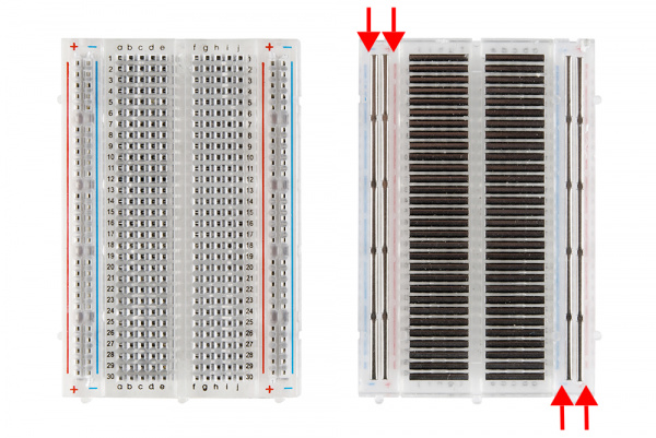
In this example we will use a breadboard to work with our electronics. If you have not worked with a breadboard before check out a page like this one. In short, breadboards allow you to connect different holes to each other if they are in the same “rail”. In the picture below you can see how different holes are interconnected:

- Making the connections
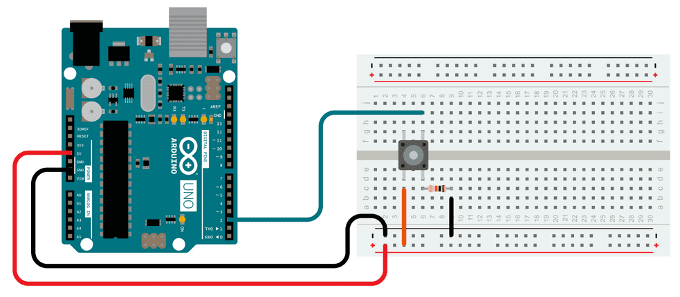
In this example, our button goes in the breadboard. These buttons work by letting electricity through if pressed and are do not make a connection when they are pressed. Make the connections as follows:

This way, 5v flows into the button so that when it is pressed, electricity flows into digital pin number 2 and when it isn’t nothing is received in pin 2. Thus the aim of the code is set pin 2 to output mode, so we can read whether there is a voltage being received (button pressed) or not (button not pressed).
- The code
The code we will use is located in the example File/Examples/02.Digital/Button as follows:
// constants won’t change. They’re used here to set pin numbers:
const int buttonPin = 2; // the number of the pushbutton pin
const int ledPin = 13; // the number of the LED pin
// variables will change:
int buttonState = 0; // variable for reading the pushbutton status
void setup() {
// initialize the LED pin as an output:
pinMode(ledPin, OUTPUT);
// initialize the pushbutton pin as an input:
pinMode(buttonPin, INPUT);
}
void loop() {
// read the state of the pushbutton value:
buttonState = digitalRead(buttonPin);
// check if the pushbutton is pressed. If it is, the buttonState is HIGH:
if (buttonState == HIGH) {
digitalWrite(ledPin, HIGH); // turn LED on:
}
else {
digitalWrite(ledPin, LOW); // turn LED off:
}
}
Let’s go over the code. Now before the setup routine, we have a few global constants and variables.
For example, const int buttonPin = 2; means that whenever we write buttonPin this will stand for its stored value: “2”. const means that the value is a constant while int means that the value is an integer.
We also have int buttonState = 0; which means that the variable buttonState is an integer and it has an initial value of 0, but we can use it as a placeholder to store numbers.
In the setup routine we use pinMode to state that the LED pin is an output and the button pin is an input.
We then go into the loop routine. The first line, buttonState = digitalRead(buttonPin); uses the digitalRead function to find out whether the button is pressed or not, and the variable buttonState we create earlier to store the state of our button. After storing the state, we can use the variable buttonState to turn the built-in LED on and off depending on the button state.
If you need more info on the code, go the example’s webpage here.
- Variations
You should attempt a few variations to understand how to repurpose examples and bits of code for your own purposes. Here are a few ideas:
- What happens if you move the wire going into pin 2 to pin 3. What changes do you need to make to the code to make it work again?
- Put an actual LED, a speaker, or anything else that will react to +5V, out of pin 13 or any other empty digital pin. Note that physical LEDs need a resistor (220 Ohms should do) when using a +5v supply.
- Add a second button, how do you modify the code to do this?