 7.1 Spectra
Although we have referred specifically to the idea of a spectrum, we haven’t really talked about it at length. Progressively, we’ll complicate this term, but in the meantime, here is a brief introduction to spectr
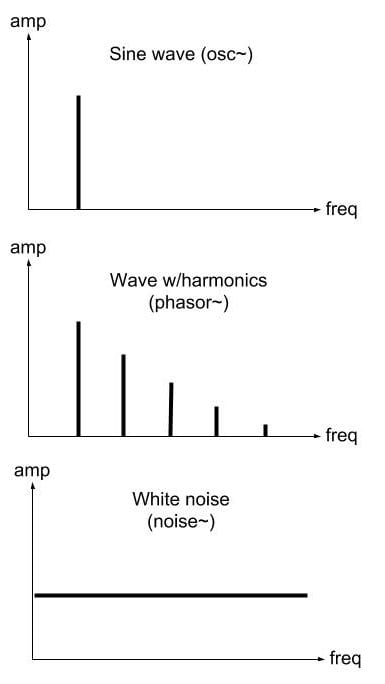
The graphs we have on the right are spectrographs. They plot the amount of energy a sound wave has at a given frequency over a specific window of time. The term amplitude is somewhat misleading as power, magnitude, or energy might be more appropriate, but I leave “amp” there to stress the change in the horizontal axis.
As mentioned earlier, the reason we use sine waves is that their waveform changes smoothly from positive to negative peaks. As shown in the graphs on the right, the smoothness of sine waves produces a waveform with only one harmonic. That is, if the frequency is 200Hz, then there is energy only at 200Hz.
Thus in additive synthesis we add multiples of a fundamental frequency to produce harmonics (i.e. 200, 400, 600, 800, and so on). However, we can produce various periodic waveforms that generate harmonics among which we find the classic square, triangle, sawtooth, and pulse waveforms. We’ll work on these waveforms in the next session.
In this session we’ll focus on the “opposite” of a sine wave, which is a white noise generator. The [noise~] generator produces a random number for every sample and the spectral result is that there is energy in the whole spectrum. Thus, the spectrum is represented with a horizontal line.
Since [noise~] has energy in all frequencies it is a great signal with which to test spectral operations.
7.2 Filters
One way to operate on spectra is by using filters. Filters take energy out from certain parts of the spectrum and let it through in other parts of the spectrum. In this class we’re going to look at the most common filters and we’re going to look at how they are used to modify spectra. We will study three basic filters and their associated objects: Low Pass Filter ([lop~]), High Pass Filter ([hip~]), and Band PAss Filters ([bp~] and [vcf~]).
 7.2.1 Low Pass Filter
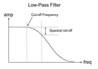
A Low Pass filter lets the spectral elements below a frequency called the “cut-off frequency” unchanged and dampens the spectral elements above this frequency. The energy of the frequencies above the cut-off frequency drop at a rate of -3dB per octave. We refer to this rate as spectral roll-off.
 In pd, we use [lop~] to achieve a low pass filter. The left inlet and only outlet, receive and output an audio signal respectively, while the right inlet and creation argument determine the cutoff frequency.
 7.2.2 High Pass Filter
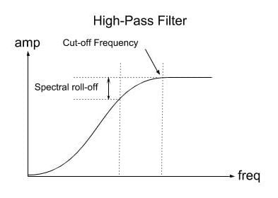
A High Pass Filter does exactly the opposite from a Low Pass Filter. A High Pass filter lets the spectral elements above a a cut-off frequency unchanged and dampens the spectral elements below this frequency. The spectral roll-off is the same.
 High Pass Filters are a great way to eliminate direct current or DC, so I always include a [hip~ 5] before going to the [dac~].
In pd, we use [hip~] to achieve a high pass filter. As with [lop~], the left inlet and only outlet, receive and output an audio signal respectively, while the right inlet and creation argument determine the cutoff frequency.
 7.2.3 Band Pass Filter
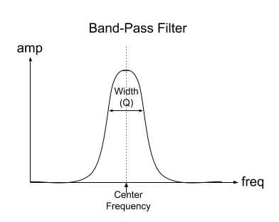
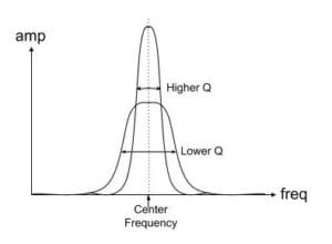
In contrast to high and low pass filters, and is its name suggests, band pass filters let through a band of spectral energy around a “center frequency”. The width of this band is controlled by a variable often referred to as “Q” and which refers to deviation from the center frequency, which is also referred to as the “width” of the filter. If a filter has a Q of 0, the default, then the filter lets through all frequencies.
 The higher the Q, the narrower the band, but also, the more resonant. In fact, band pass filters are what we often refer to as resonant filters when they have enough Q. That means that given an input signal with energy at the center frequency of the filter, this will make the filter sound at that frequency for a while.
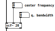
 The two objects we use to implement a band pass filter in Pd, are [bp~] and [vcf~]. [vcf~] is a little bit more expensive computationally, but some argue it sounds better, but more importantly, it allows you to control the center frequency with an audio signal as well as a constant. Again, the left inlet receives the input signal, and the left outlet outputs the filtered signal. The center inlet controls the center frequency either by sending a number or by sending an audio signal. Finally, the right inlet and creation argument, control the filter’s “Q”.
.
 7.3 Filters in Series
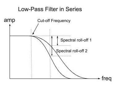
 When we place filters in series, that is, connecting the outlet of one to the inlet of another one, we are in fact filtering a signal that has already been filtered. In the example on the right we use two low pass filters [lop~] with the same cutoff frequency. By placing them in series, their spectral roll-off becomes more pronounced as we are in fact filtering the filter. In this sense, we are multiplying their frequency responses.
.
 7.4 Filters in Parallel
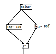
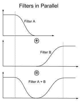
In contrast, when we use filters in parallel, that is, by filtering the same signal and adding their outputs, we also add their frequency responses.