This week we dove into digital input/output and analog input. For most of the assignments, I decided to cut and strip my wire instead of using jumper cables. I found that the jumper cables were too long and made the board turn into a nest of wires. It also looks much nicer!
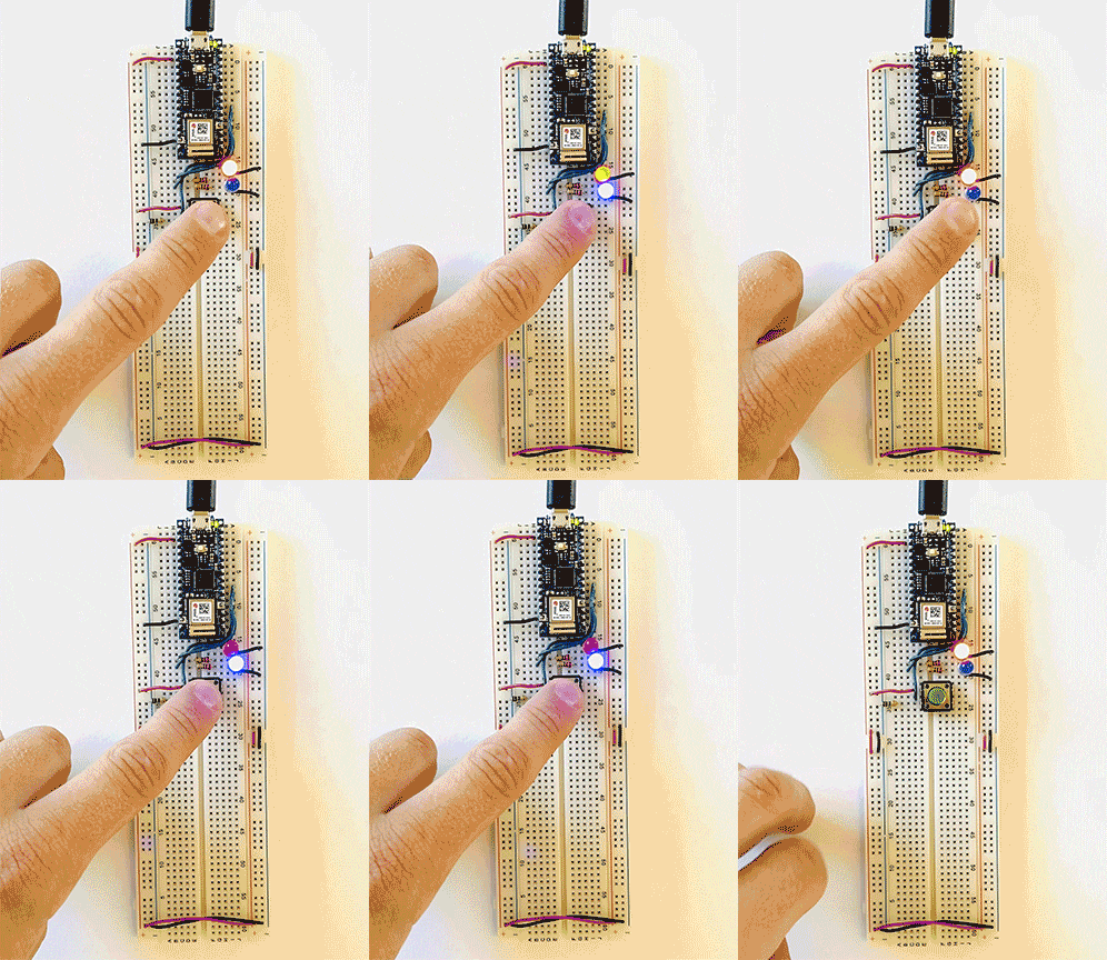
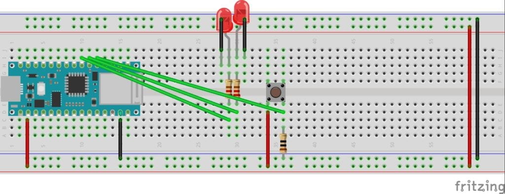
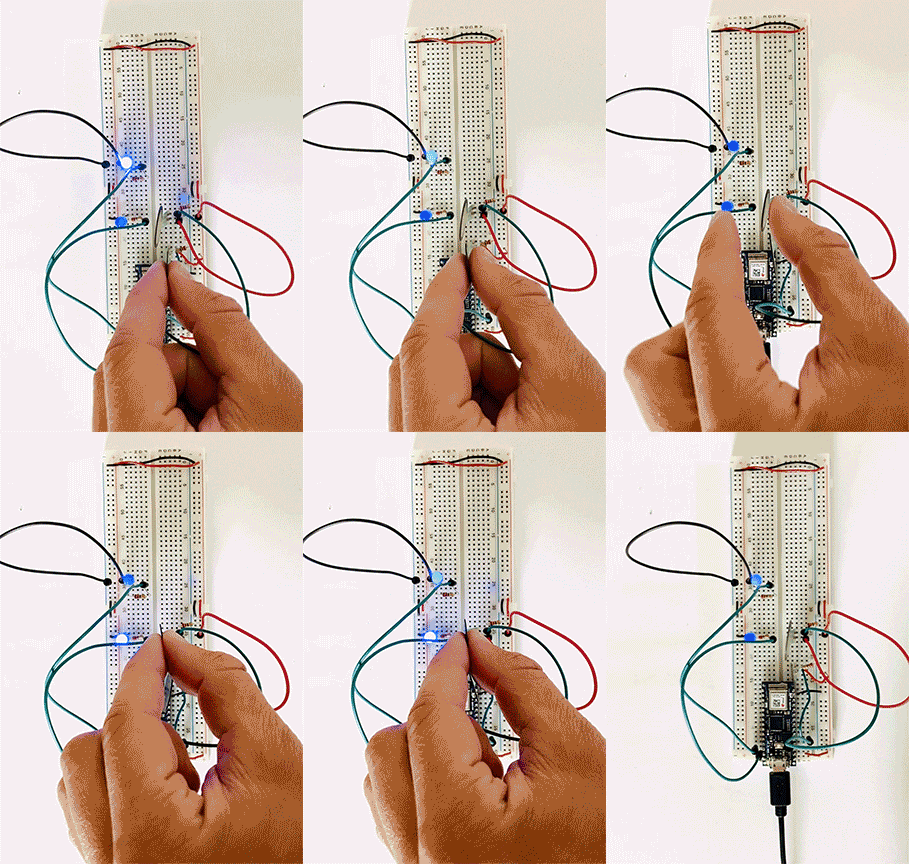
For the first lab, I connected two LEDs to a switch. This lab didn’t give me much trouble.
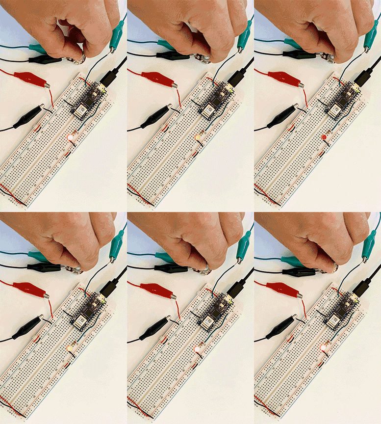
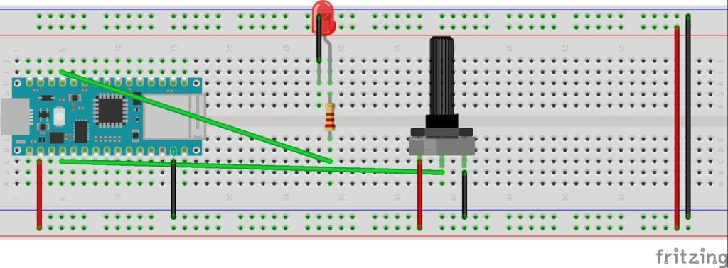
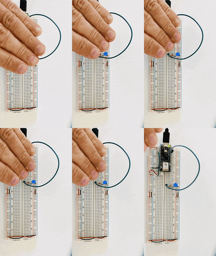
Next, I removed one LED and wired a potentiometer into my breadboard. After putting the new code on the Arduino, everything worked perfectly.
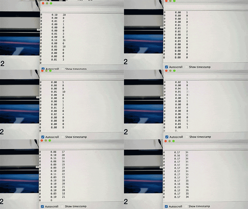
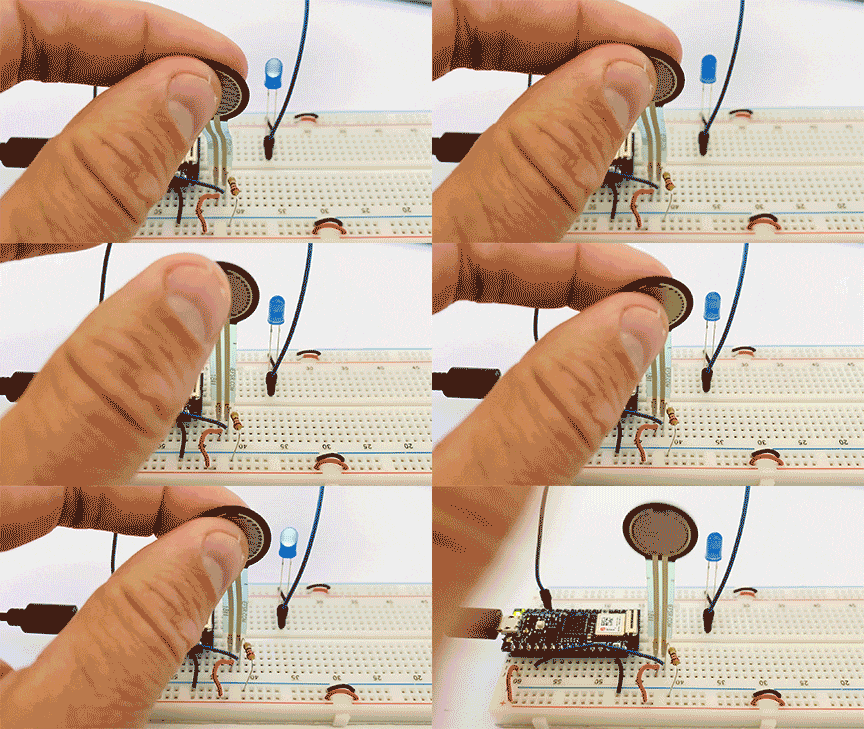
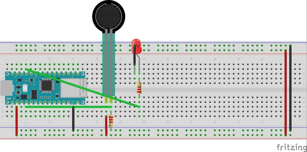
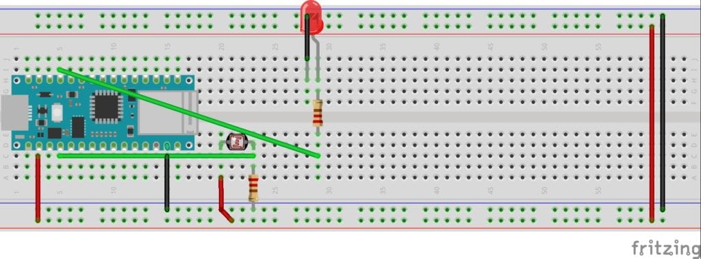
Everything started so well until I moved to the sensors. After wiring the breadboard, I ran the serial monitor in the Arduino software. I was surprised to see a very low reading when I pushed really hard on the pressure sensor or completely blocked the light on the phototransistor. I wire and re-wired the board, tried new sensors, and saw no change. To get the LED to light-up properly, I mapped the sensors and changed their settings based on my low readings. The mapping worked, but I wanted to figure out what was going wrong. In a group office hour, the residents told me to check my resistor. They were correct. I was using a 10 Ω resistor when I should be using a 220. After swapping out the resistor, my sensors worked as expected. I had to remap them with the new readings. I read the color-coding wrong when picking my resistor, a simple error that provided hours of confusion.
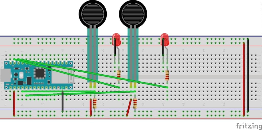
For the final build, I decided to use two pressure sensors and two LEDs. This wiring got fun! And with my new appreciation of testing and measuring my resistors, I was able to get this circuit up and running quickly. I reached out to Danny regarding the blinking of my LED’s when I wasn’t activating the sensor, and he suggested using the constraint command to limit the circuit. I tried coding this, but I couldn’t get it to run. This is my main question for next week’s class. I can see how this extra power could play havoc on a circuit in the future.

