Light Sculpture Prototype

Assignment 1: Light Sculpture Prototype

For this piece, Jingyao, Nick, and I wanted to make a sculpture that relied on the light projected on it as much as the shadow is produced. 

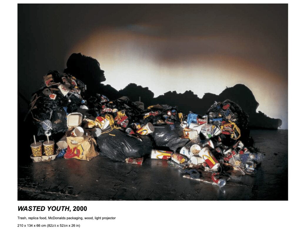
We were influenced by Tim Noble and Sue Webster’s work below. 

Image of trash projecting a perfect shadow of a couple lounging.

Image from the artist website: Timnobleandsuewebster.com

Conceptually we were interested in exploring the theme of designed obsolescence and e-waste. 

“About 6.9 million metric tons of e-waste was produced in the US alone in 2019, according to Global E-Waste Monitor, a research group that tracks electronic waste. That’s about the same weight as 19 Empire State Buildings. Of that, only about 15% was collected for recycling. And some of the minerals and metals being thrown away with our e-waste aren’t just valuable; they’re toxic.” –CNBC.

The article above points out the global scale of this problem, but we face the same issue on a smaller scale here at ITP, with projects being discarded after presentations. Recycling programs exist, for example, the ITP Junk Pile, but we believe this problem needs to be more seriously addressed. 

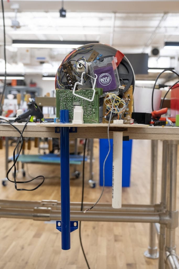
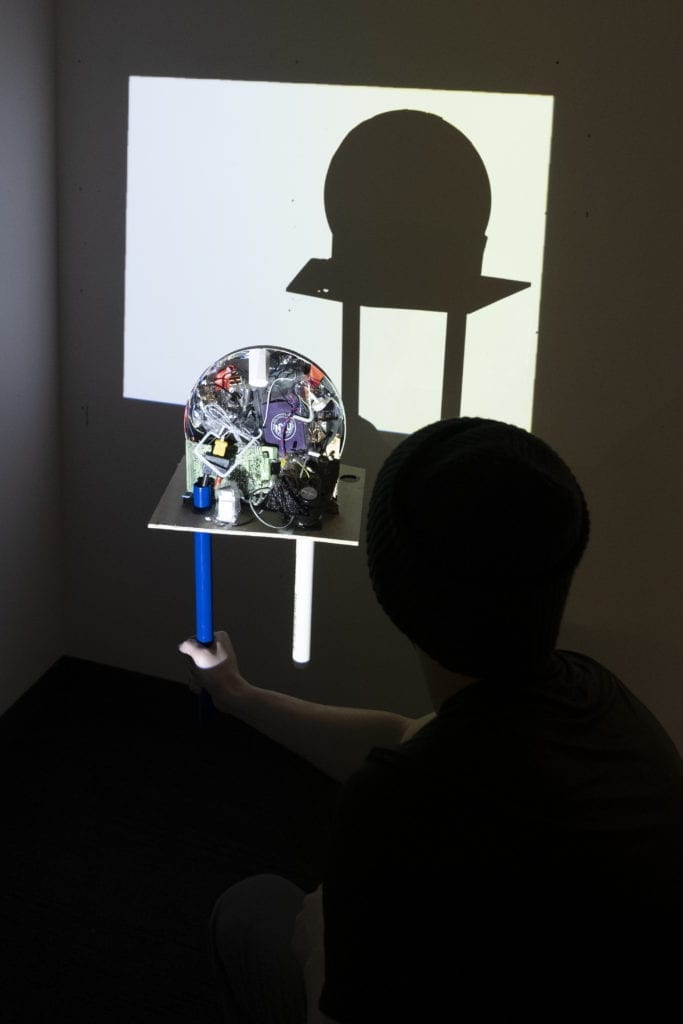
For our piece, we decided to make a LED, an object that came to all our minds when we thought of ITP, using trash from the Junk Pile and a projector.  Below is our process. 

The Build: We wanted to create depth and clutter without losing the shape of the LED.

Building of trash sculpture

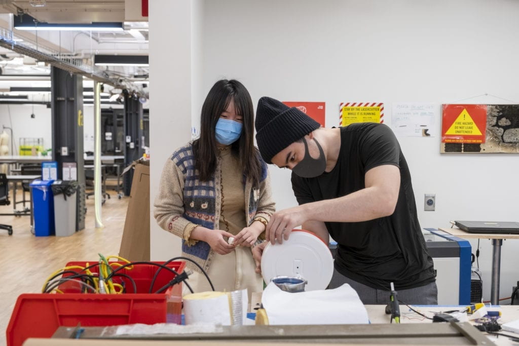
Jingyao and Nick building

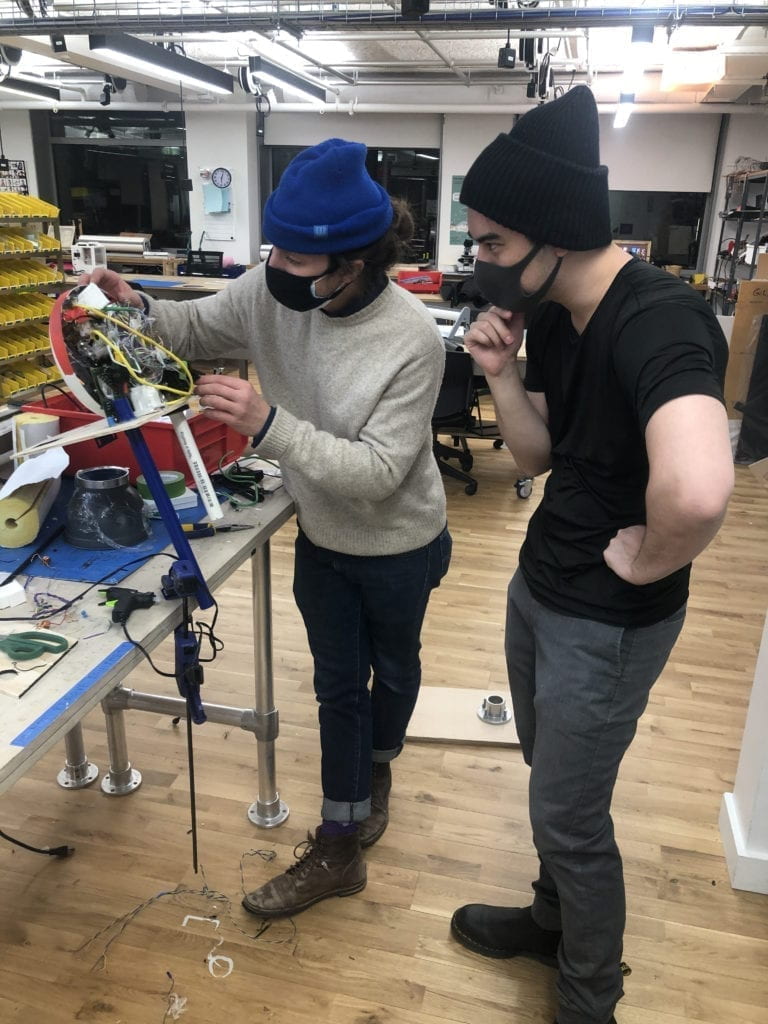
Alan and Nick building a sculpture

Testing: As we added layers, we needed to test the sculpture with a projector to make sure it was maintaining the silhouette.

Testing the sculpture shadow

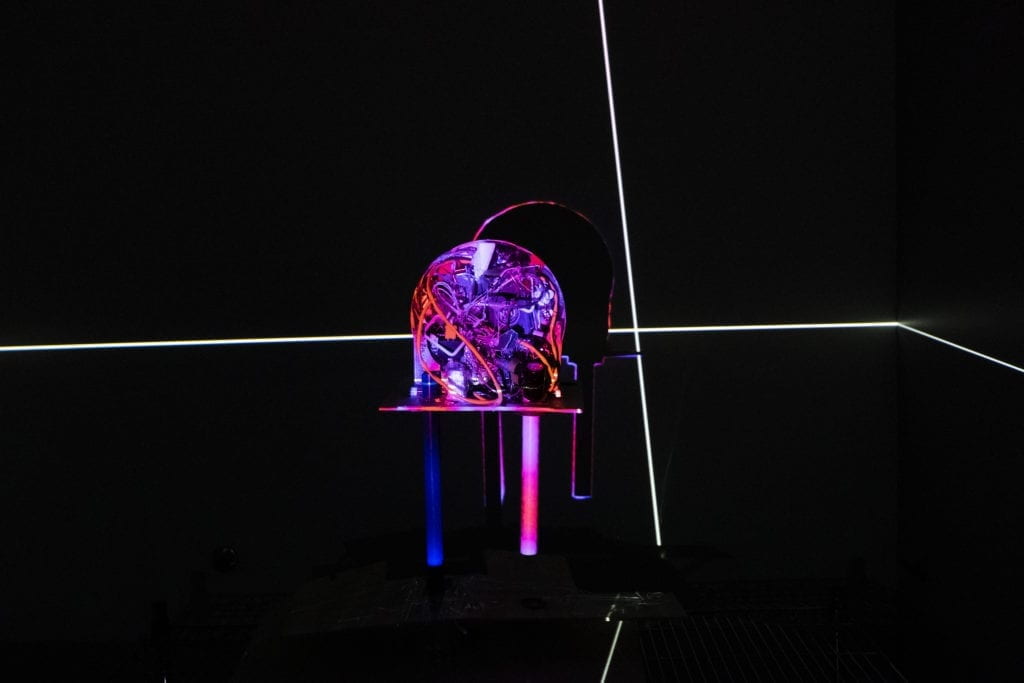
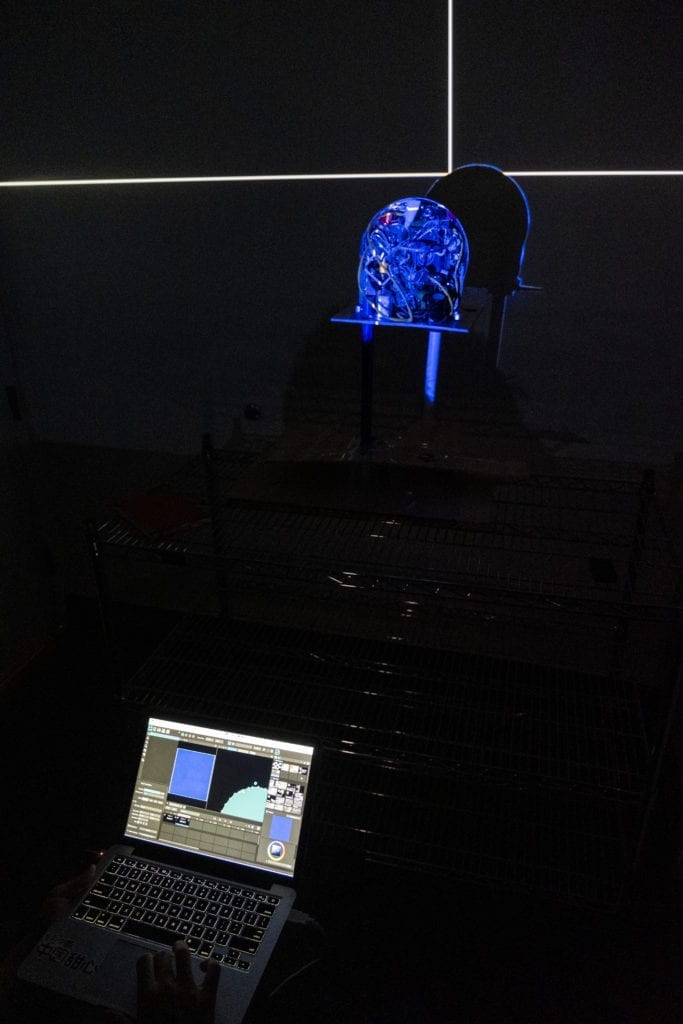
Masking: We used Madmapper to mask the sculpture when the colored light was projected on it. 

Masking a projection

Testing the sculpture

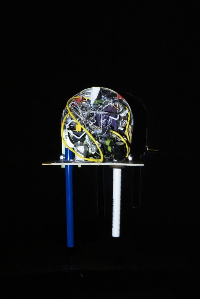
Mask Test: White light test to make sure the masking was working. 

white light falling on sculpture

Presentation: When the piece is up and running, the projector cycles between a red light and white light. The red portion uses the mask to only shine on the sculpture while the white light washes over the entire wall revealing the LED shape behind. 


To wrap up, we experimented with alternating patterns and colors. 

Components – Breadboards – Switches

The first set of labs for Physical Computing was all about the basics of electricity, including measuring it, understanding components, terminology, and making simple circuits like lighting an LED and using switches. I was eager to jump into the building after reading and watching all the necessary materials. 

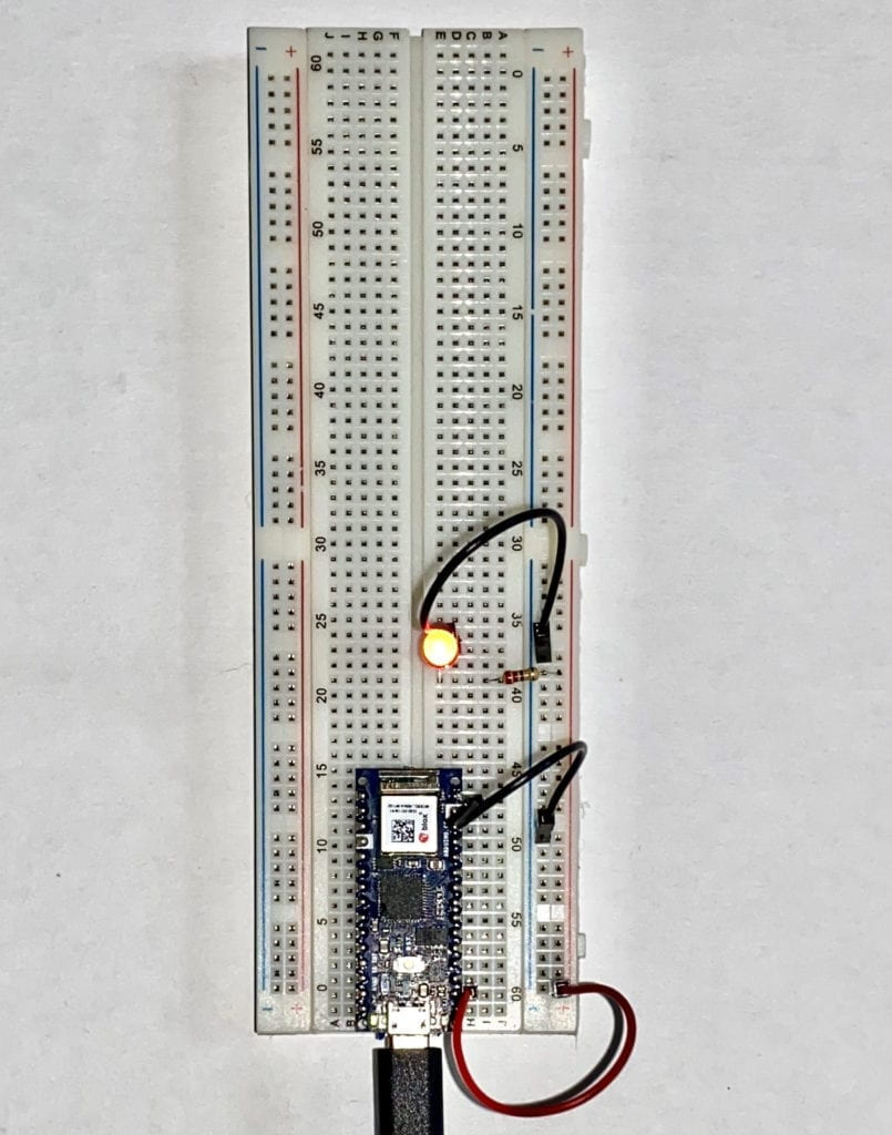
My first simple circuit was a huge success. 

A simple circuit lighting up one LED.

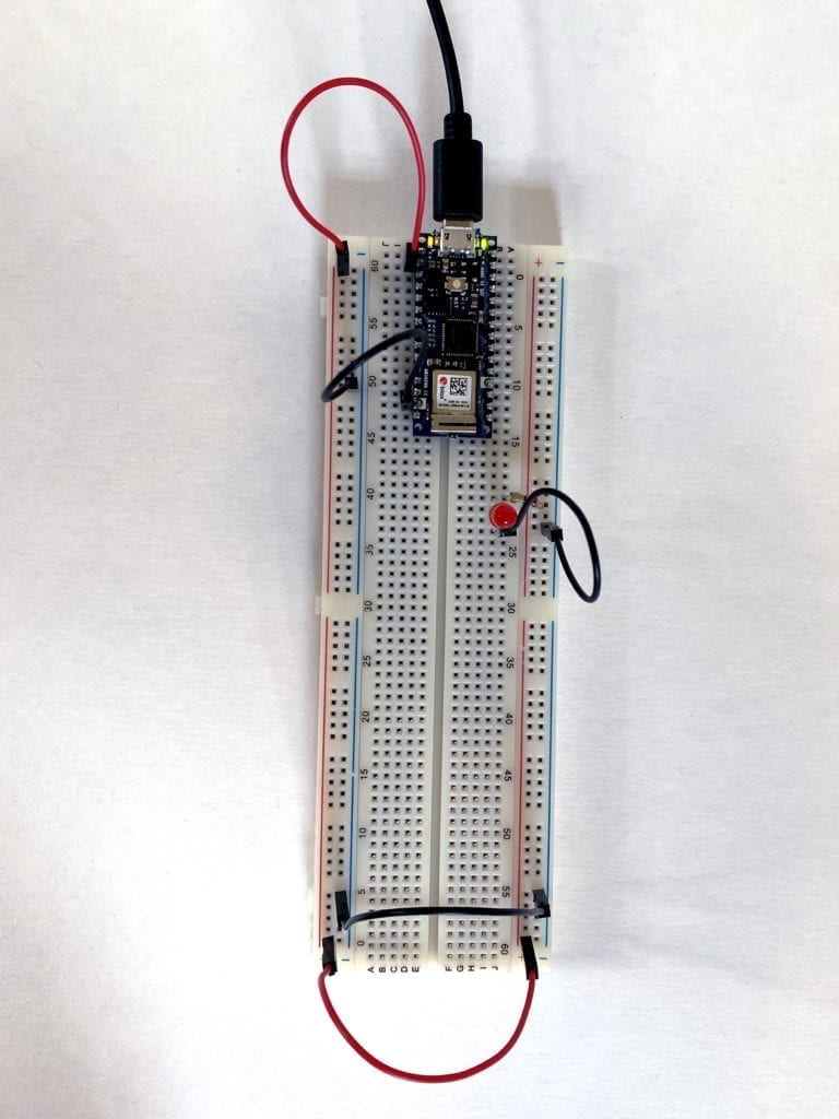
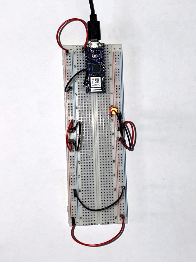
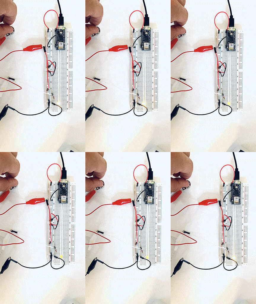
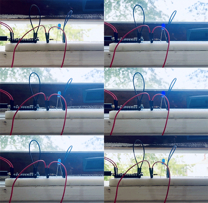
I soon ran into a problem with my second circuit. I attempted to move the LED to the other side of the Breadboard. I thought if I connected jumper wires at the bottom from the left side to the right, it would work correctly. It didn’t.

A failed circuit with the LED not lit up.

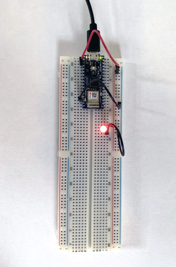
I started to experiment by removing the lower jumper cables and plugging the power and ground to the same side as the LED. Success! I now knew the Breadboard worked, and I was doing something wrong. 

A simple circuit lighting up one LED.

After looking at the Breadboard a little longer, I noticed a larger gap at hole 30 on both the left and right sides. I had a feeling that the + and – columns were not connected all the way. To test this, I moved the power and ground back to the left side and used jumper cables at hole 29, connecting the sides. Success again!

A simple circuit lighting up one LED.

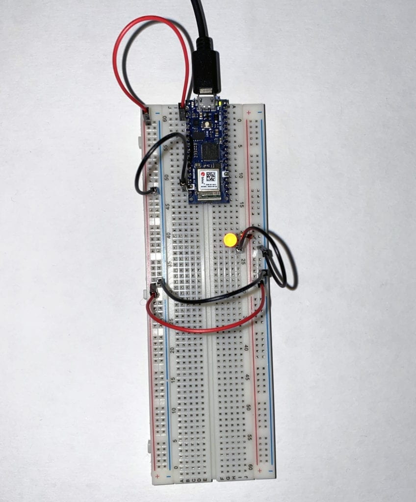
Armed with this new insight, I tried to connect the Breadboard entirely around. Success! 

A simple circuit lighting up one LED.

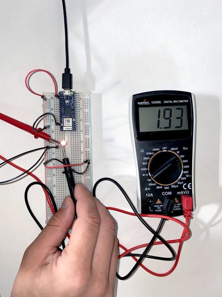
Feeling more confident, I moved on to the next section of the Lab that had to do with measuring currents. 

An image of a multimeter measuring the current running to and LED on a breadboard.

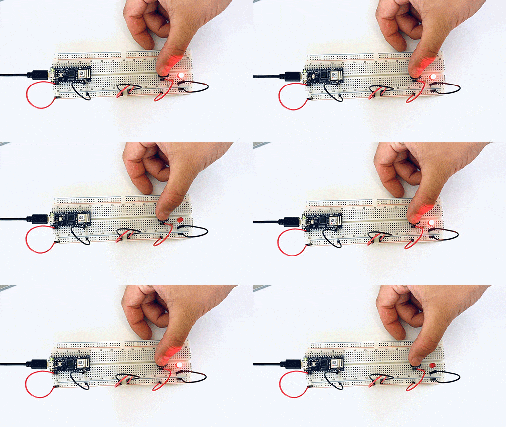
Then to switches and adding components in a series to see how the power would or would not be diminished. 

A gif of a breadboard wired with one switch and one LED.

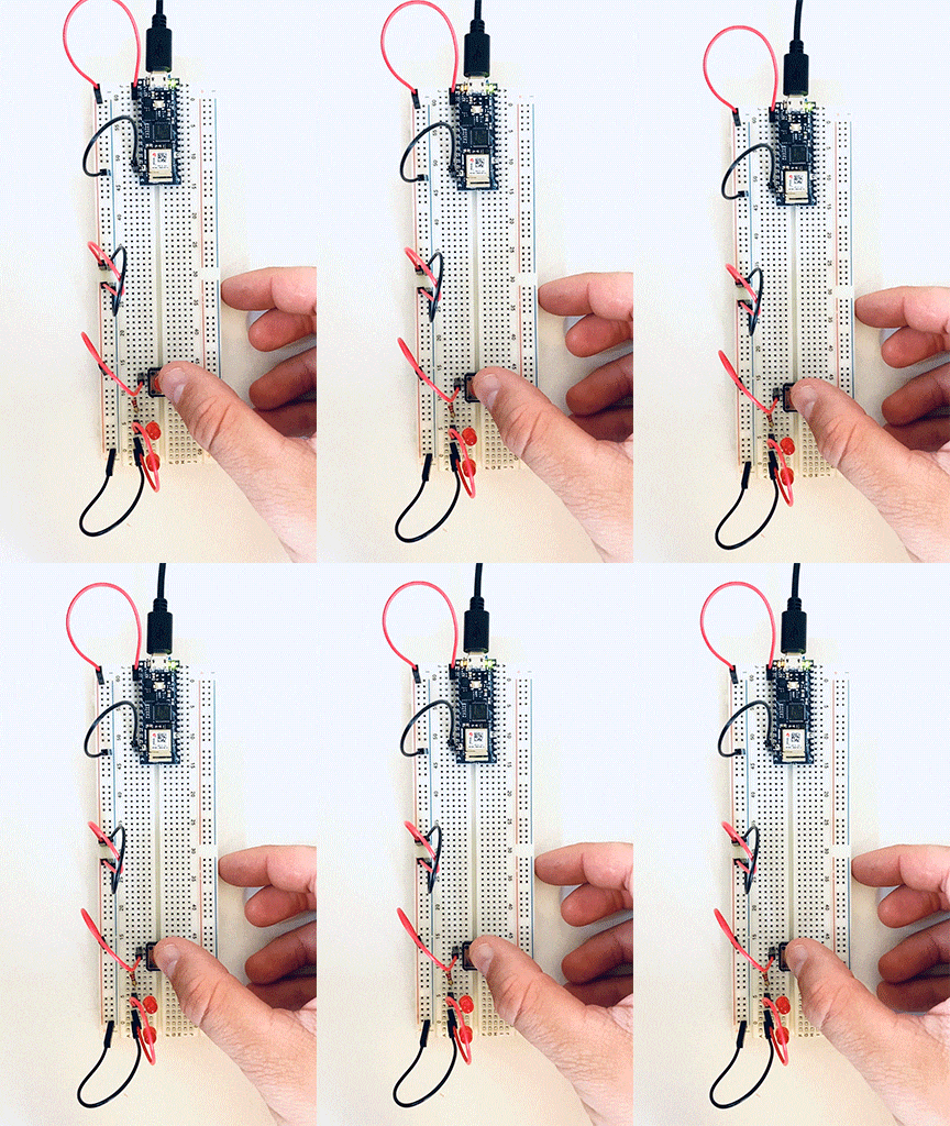
As I continued to add components in a series, I noticed a voltage a luminance drop throughout the circuit. 

A breadboard wired with a switch and two LEDs in a series.However, when I place the LEDs in parallel, I didn’t see the drop in power or luminance. 
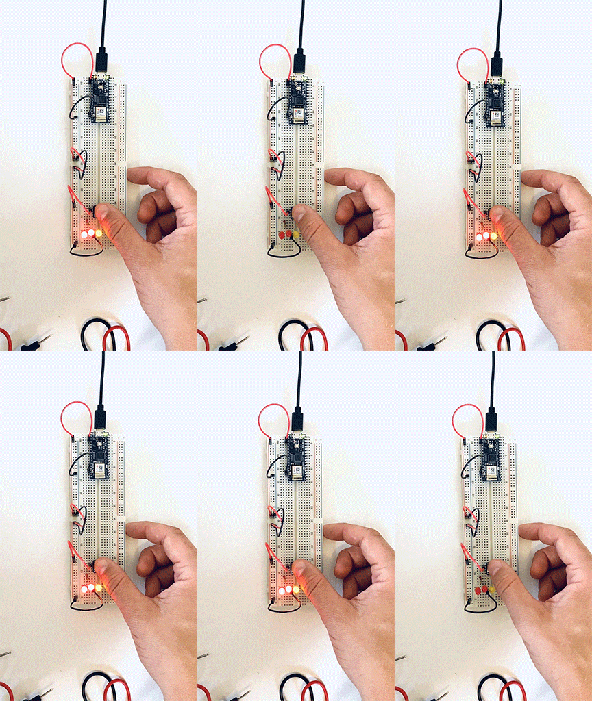
A gif of a breadboard with a switch and three LEDs wired parallel.

Next, I moved on to measuring variable voltage by using a potentiometer. There was a constant power reading between the two side points, but when I measured between a side point and the middle point, there was a change depending on how much I turned the wiper.

A gif of a breadboard wired to a potentiometer and a LED.

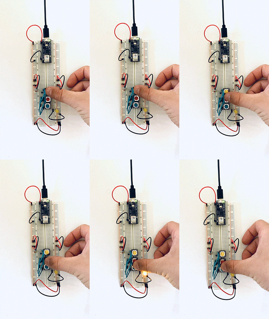
I then moved on to working with switches first in parallel than in a series. This first switch, I had to wire three times before I got the circuit correct. 

A gif of breadboard with three buttons and two LEDs. The switches are wired in parallel.

Another example of three switches in parallel, but this time, I added a second LED. 

A gif of breadboard with three buttons and two LEDs. The switches are wired in parallel.

Three switches in a series. The user needs to activate all three switches to complete the circuit. 

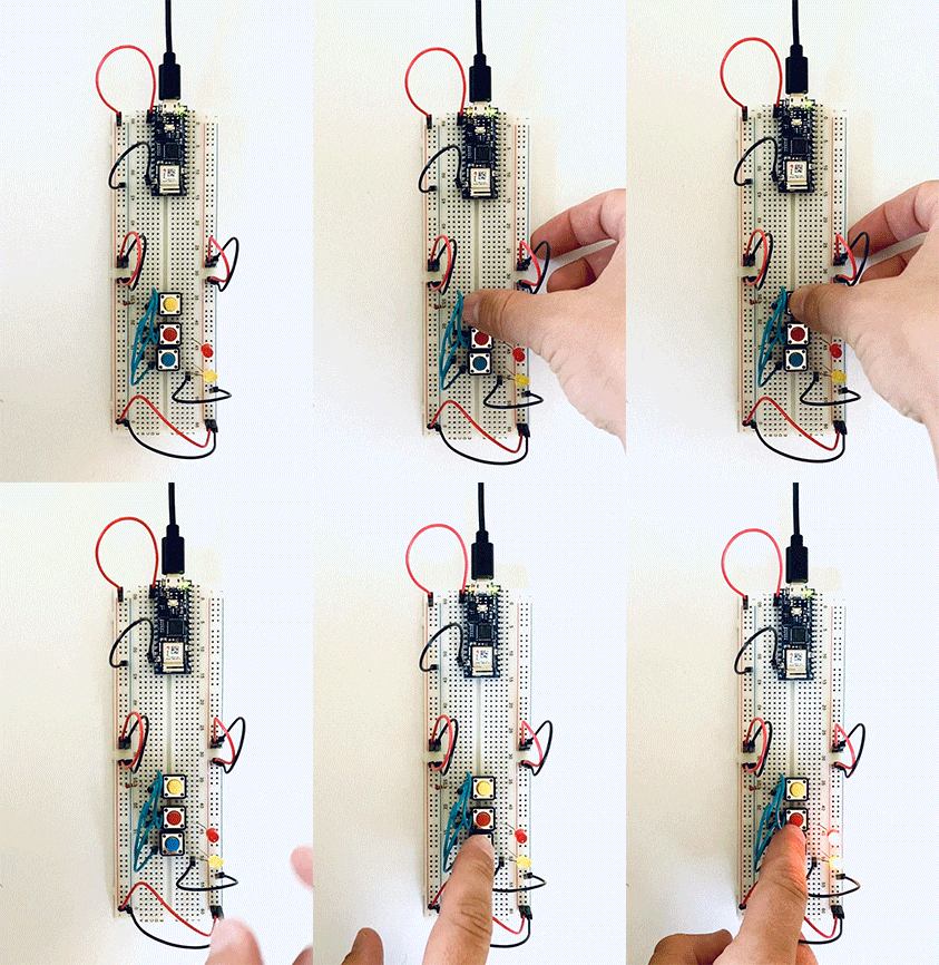
A gif of a breadboard wired with three buttons in a series with one LEDHere I placed one independent switch and two in a series on the same circuit. 
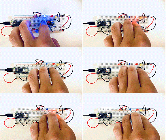
A gif of a breadboard wired with three buttons and three LED's, two buttons are in a series one is independent.

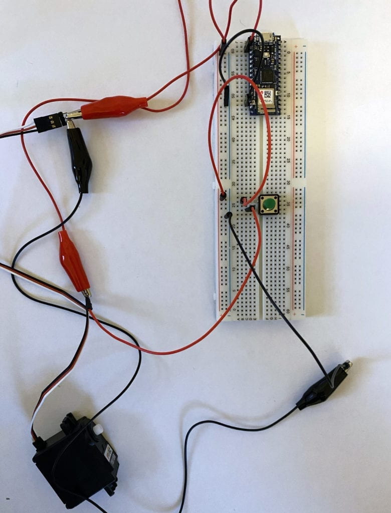
My attempt to add a motor failed. I don’t fully grasp the signal wire and believe that it needs to be coded into the Arduino. I spoke to some of my classmates, and they confirmed this.

I’m looking forward to investigating this more to get it up and running. 

Failed attempt to wire motor into a breadboard with a switch.

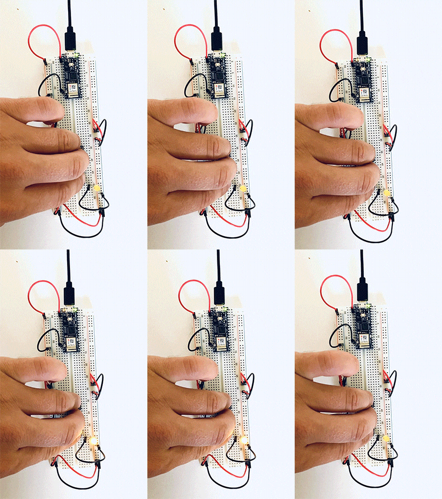
To wrap up the labs, I made a custom switch – The Window Switch; when the window is closed, the LED lights up. 

A gif of a breadboard and an LED wired to a window.