Time Final

I’m tossing around two ideas for my final project. 

The first idea is a solar-powered television, set to a static channel. I find it fascinating that 1% of the static on old television screens is the leftover glow from the big bang. To power, the display with the sun seems to be fitting. I would build a custom housing to place the television in and leave it permanently on a static channel playing the most incredible show on earth. 

Reference article here

My second idea is to carve a globe on the lathe. I’m thinking of creating two bowls that can fit together inside the bowls will be the circuit to power a light. The light will rotate around the globe like the sun. 

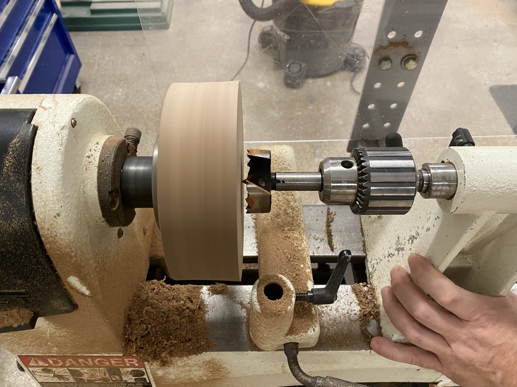
I started testing my lathe skills today and like the results.

turning wood on a lathe

Pixel by Pixel Final – Experiments with perlin noise

For my final, I wanted to experiment with Perlin Noise in a live video feed. 

First, a little on Perlin Noise and why it’s so beautiful. From WikipediaPerlin noise is a procedural texture primitive, a type of gradient noise used by visual effects artists to increase the appearance of realism in computer graphics. The function has a pseudo-random appearance, yet all of its visual details are the same size.

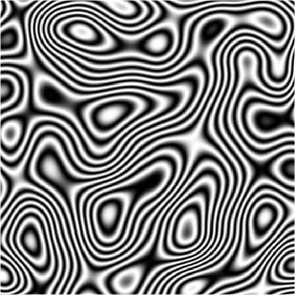
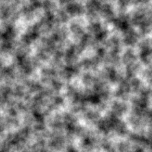
Examples: I’m drawn to the smooth-flowing randomization of the texture. 

Example of Perlin Noise

Example of Perlin NOise

For my piece, I wanted to work with the motion of Perlin Noise but isolate it to a single point that distorts and eventually destroys the original video feed. I didn’t realize it until I built it, but it appears to be a virus methodically taking over the screen. 

Code:

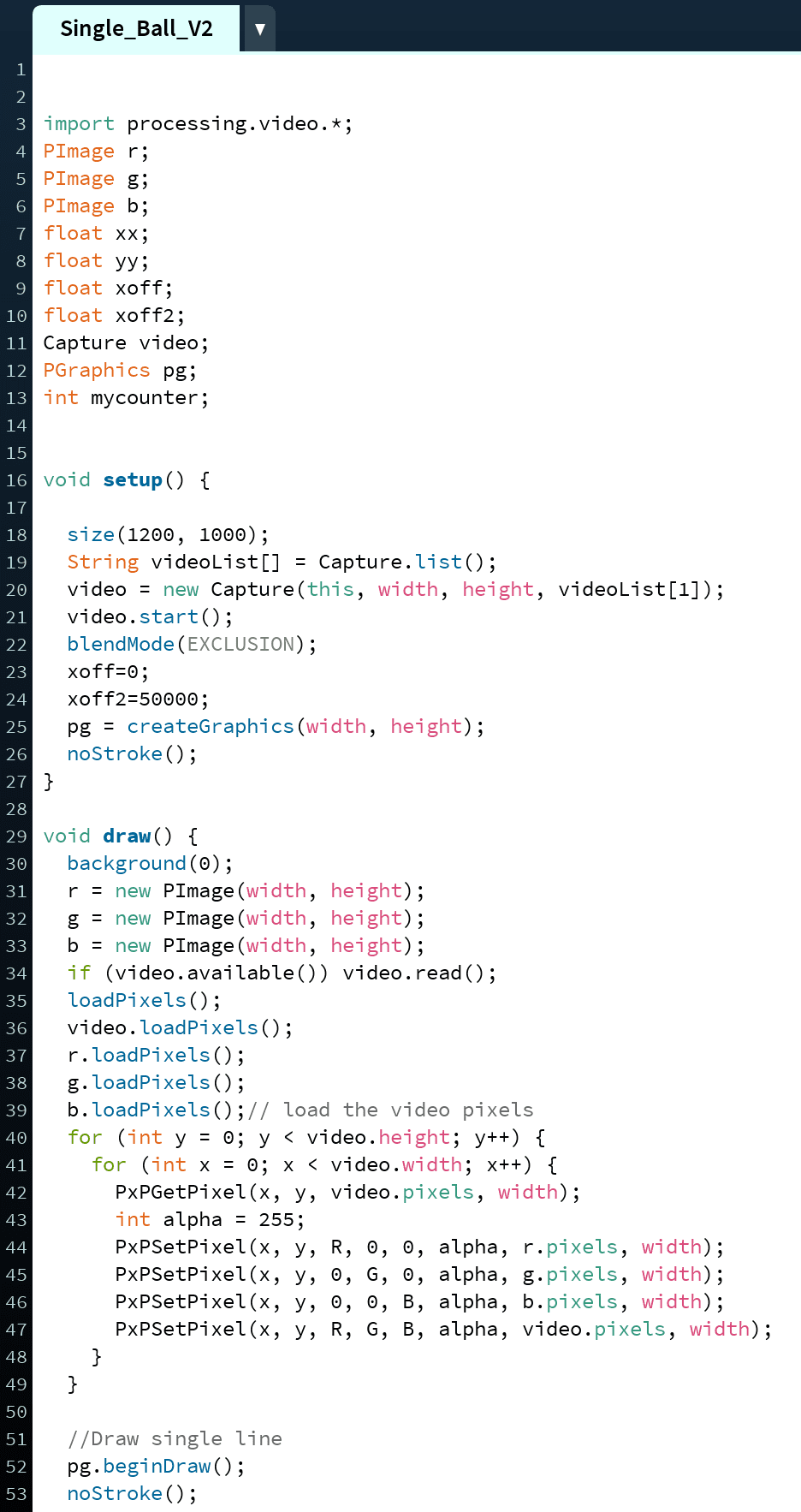
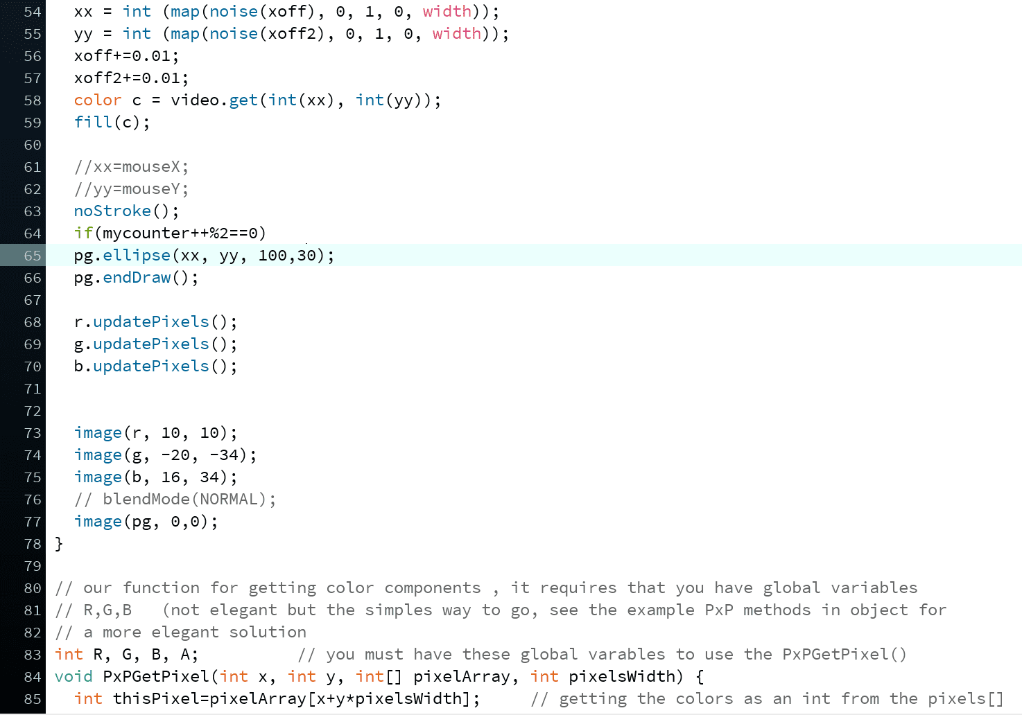
To achieve this sketch, I needed to learn how to produce the noise and deconstruct it into a single point. For the “noise walker,” I called the noise function and played around with the math to get it moving in a pattern I enjoyed. 

For the live video feed to continue to work, I needed to call a background, but the “walker” doesn’t work with a background to achieve a printing effect. I needed to call the PGraphics function to print the ball.

Finally, the ball was printing too often. I originally worked with frame count to slow it down, but that seemed to affect the video feed drastically. Instead, I isolated the printing to every two frames with an if statement. 

Thank you to Danny Rozin for walking me through several coding blocks throughout this process during office hours. 


Example 1
Example Code 2

Finals Piece: 


Fitting In – Version 2

For our Video Sculpture final, Noah and I decided to re-work our 2nd project Fitting In. 

Description:

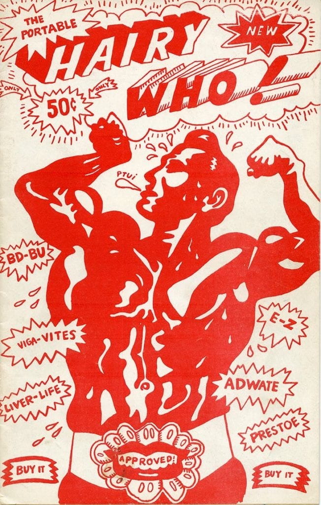
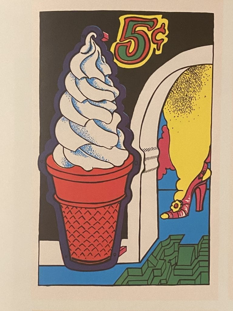
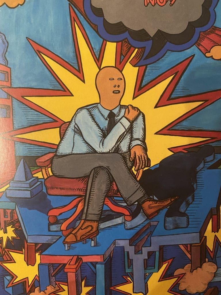
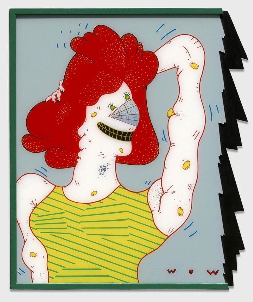
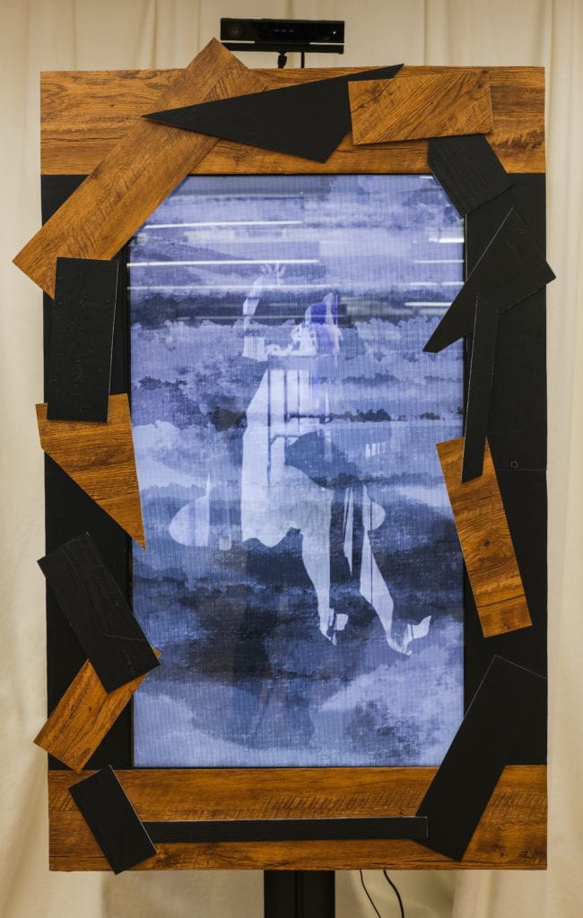
Using the 1960’s artists collective, the Chicago Imagists, as a reference Fitting In explores the notion of accumulating to our surroundings. The viewer distorts their own body to fit within the exaggerated silhouettes. After performing for the frame, the viewer is then presented a six-second video clip of their actions.

Fitting In allows the viewer to confront their own experience of fitting into societal “traditions,” “practices,” and “norms.” The silhouettes are intentionally floating, distorted, or exaggerated, making them impossible to replicate, further emphasizing the endless struggle to keep up that many face. We believe that the impact of seeing one’s self will be more significant than presenting abstracted characters.

Inspiration: 

Harry Who – Six Chicago-based artists from the School of the Art Institute – Jim Falconer, Art Green, Gladys Nilsson, Jim Nutt, Karl Wirsum, and Suellen Rocca.

Harry Who

Harry Who

Harry Who


Production: 

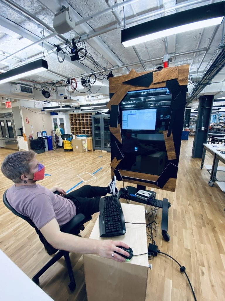
For this version, we decided to scale the entire project up, and instead of using a projector, we opted to build the entire piece around a 48-inch monitor.

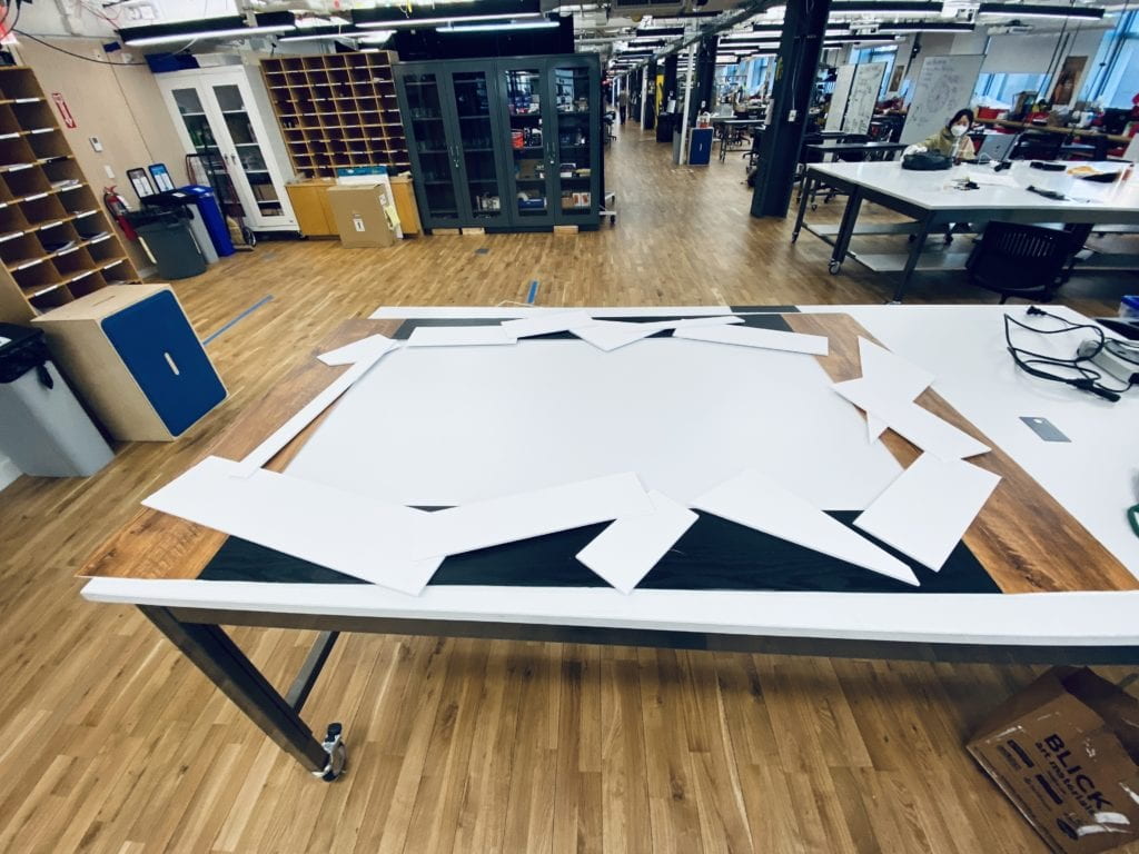
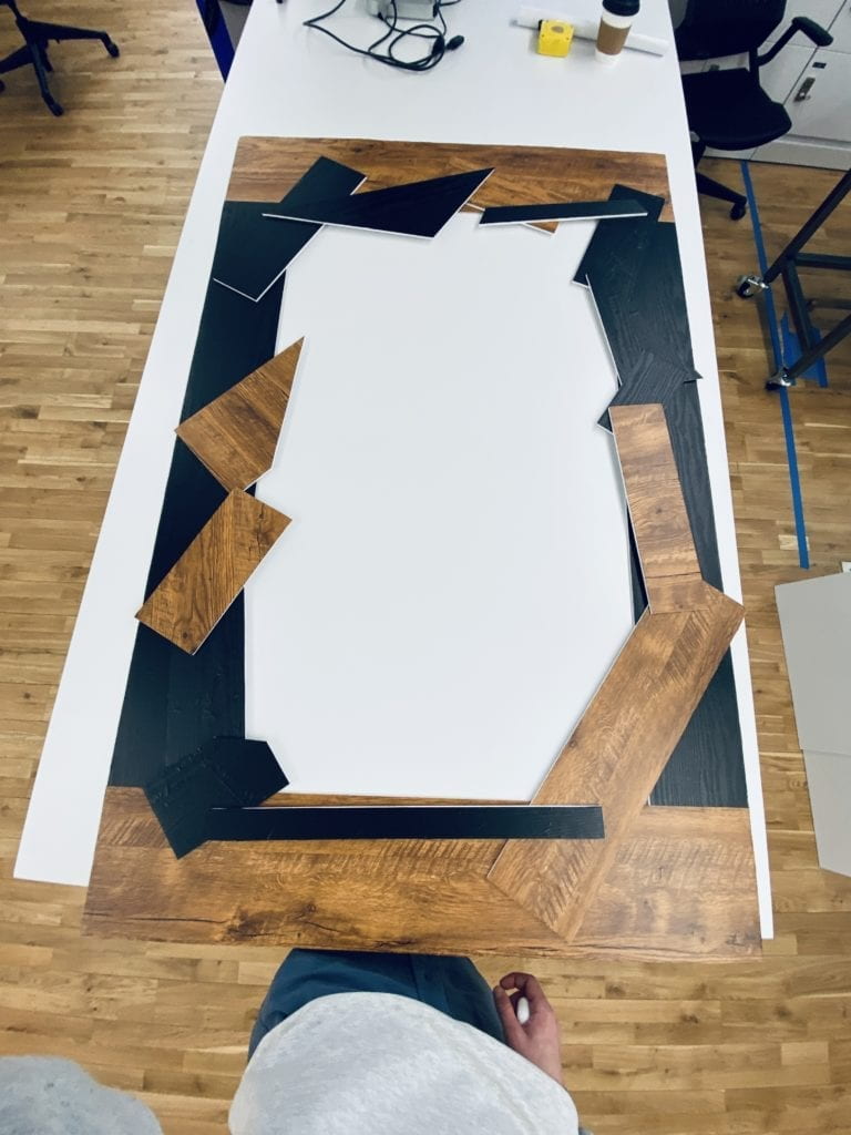
Harry Who often used alternative framing for their pieces. We decided to build our frame out of foam core and wrap it in fake wood paneling to stick with that style. 


Production

After completing the frame production, our Isadora sketch was re-worked to fit the new aspect ratios of the monitor. 

Final Piece:

In our original piece, we projected on hand-painted acrylic sheets. To keep that aesthetic, we made painted layers in photoshop to layer over the video feeds. This broke up the glare and rich color of the monitor. 

Interaction: 

Output: 


Going Forward:

Both Noah and I want to push this piece further and bring the interaction into Unity. We believe that the user triggers and mapping will be much cleaner and the overall software will be much more stable. 


PCOMP Final


For my PCOMP final, I decided to combine a few of my favorite things, data visualization, and surfing. My goal was to measure my acceleration on a wave, graph the data, and present it in a physical form. 

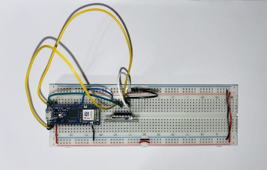
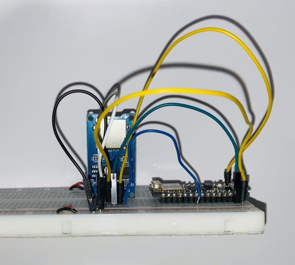
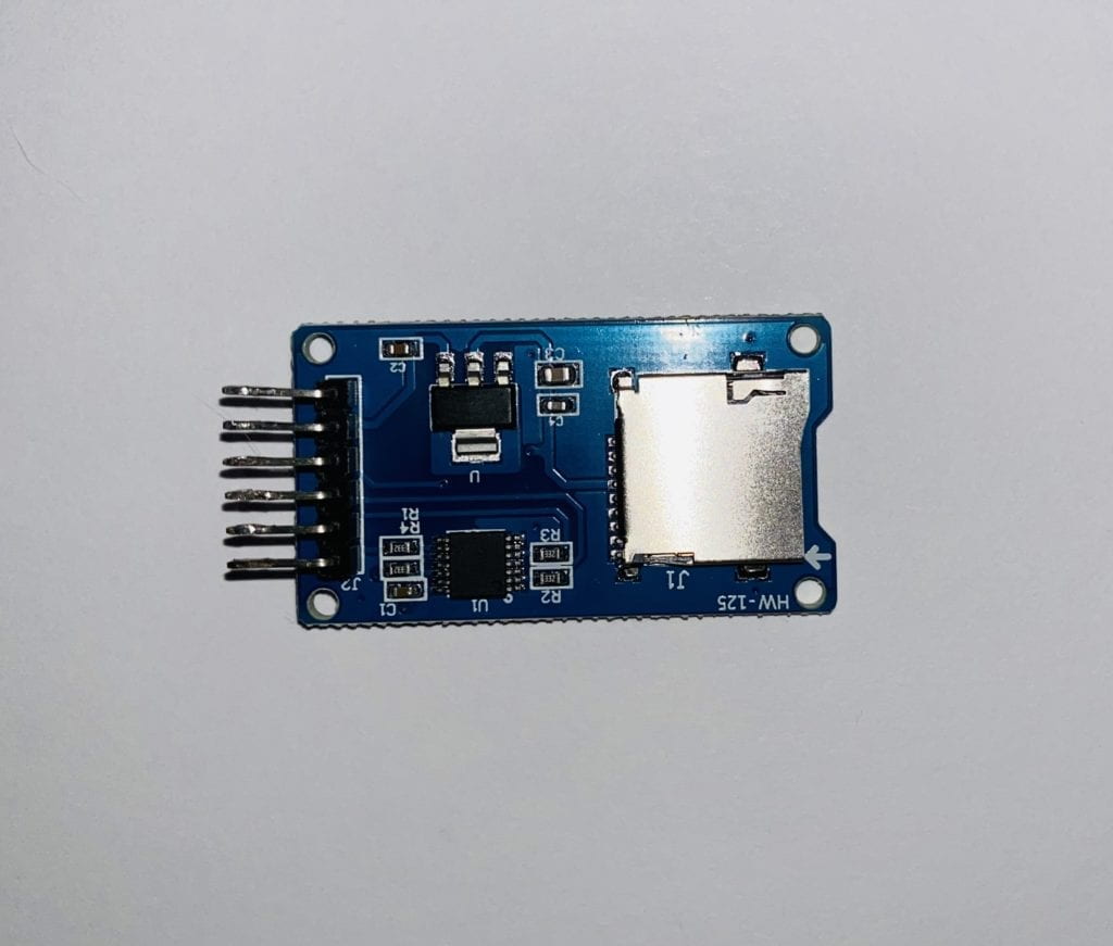
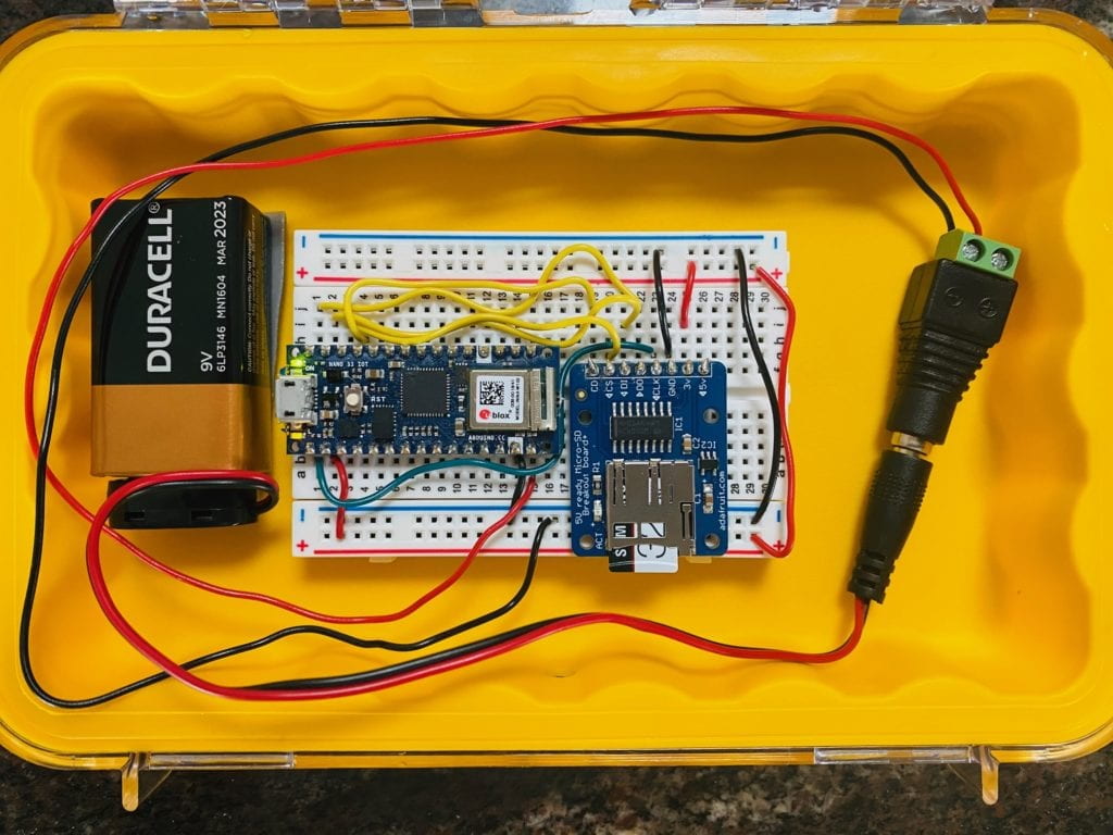
The first step was to get the circuitry up and running on dry land before taking it out in the water. This didn’t prove easy because I couldn’t get the SD card reader to link up with my Arduino Nano 33 IoT. After spending just under a week working on the problem and going to office hours, I decided to try a new board—Sarah Ro to the rescue with a board that worked immediately with the same wiring. I still have no idea if the original boards were faulty or I was doing something wrong, but that’s a problem to figure out over break. With the board up and running, I put my setup in a waterproof housing and got it down to the beach. 
It was a cold December afternoon, but I was determined to get out in the water and test it out. I couldn’t find a way to mount the device to my board successfully, so I decided to put it inside my wetsuit. With everything all set, I paddled out, hoping that the case was waterproof, the circuit would keep working in the rough water, and it was recording data. 

*I got a lot of weird looks with a rectangle shape on my back. 
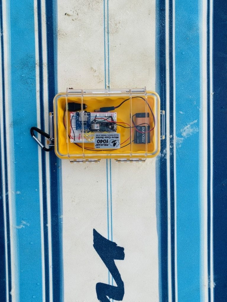
Surfboard and Arduino

Just under an hour, I paddled back in the cold and hoping for the best. To my surprise, everything was still working. The glue came undone, and the board was rattling around, so I need to address that later. 
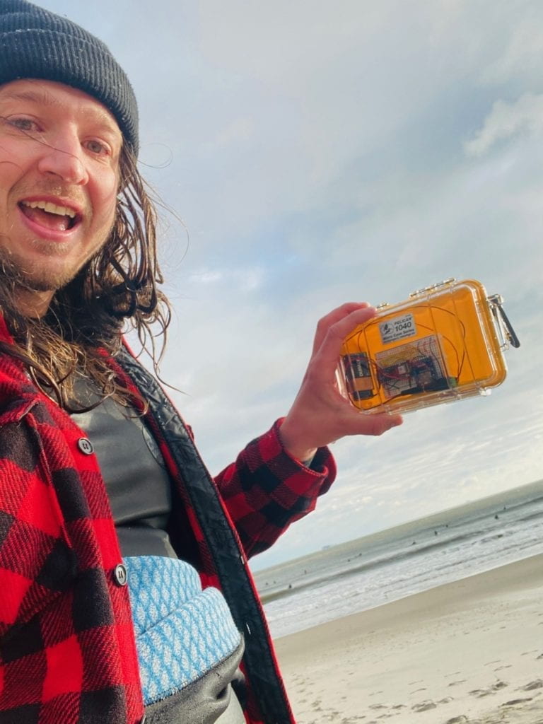
Surf Board Installation

My excitement caught the attention of some strangers on the beach who took my photo after explaining what I was doing. 
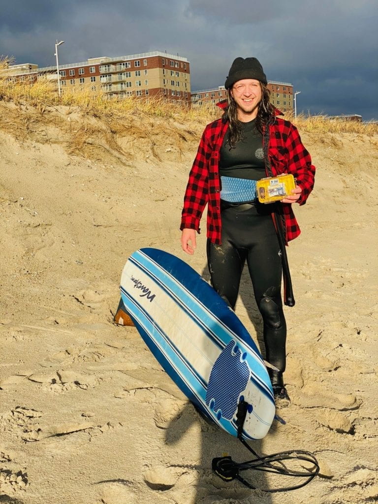

Surf Board Installation

Back home, I was able to upload and explore the data, which all came through!
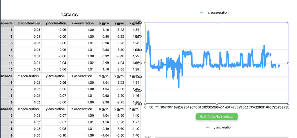
Data Sheet 1

Data Sheet 2

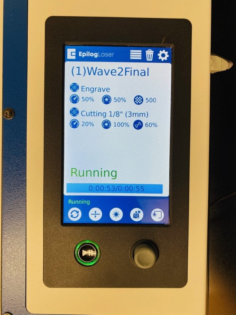
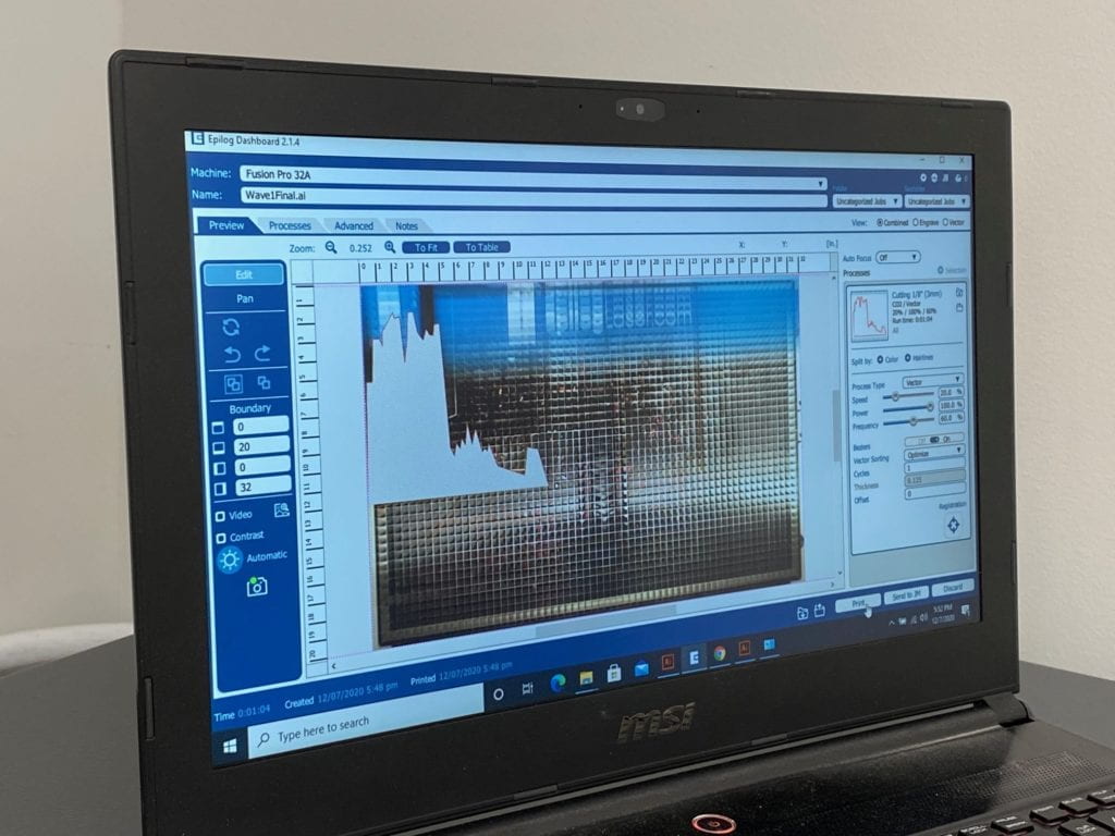
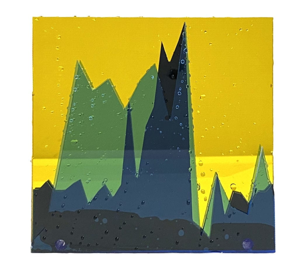
The next step was to make a physical product of the data. In illustrator, I used the Pen Tool to make a path of three waves that I rode in the session. I then put each wave on its own blue acrylic plastic piece and cut them in the laser cutter. 
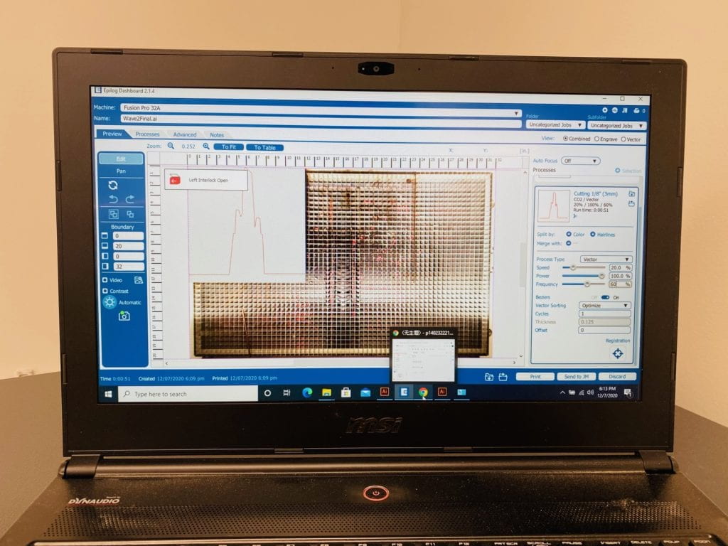

Laser Cutter Screen

Laser Cutter Screen

Laser Cutter Screen

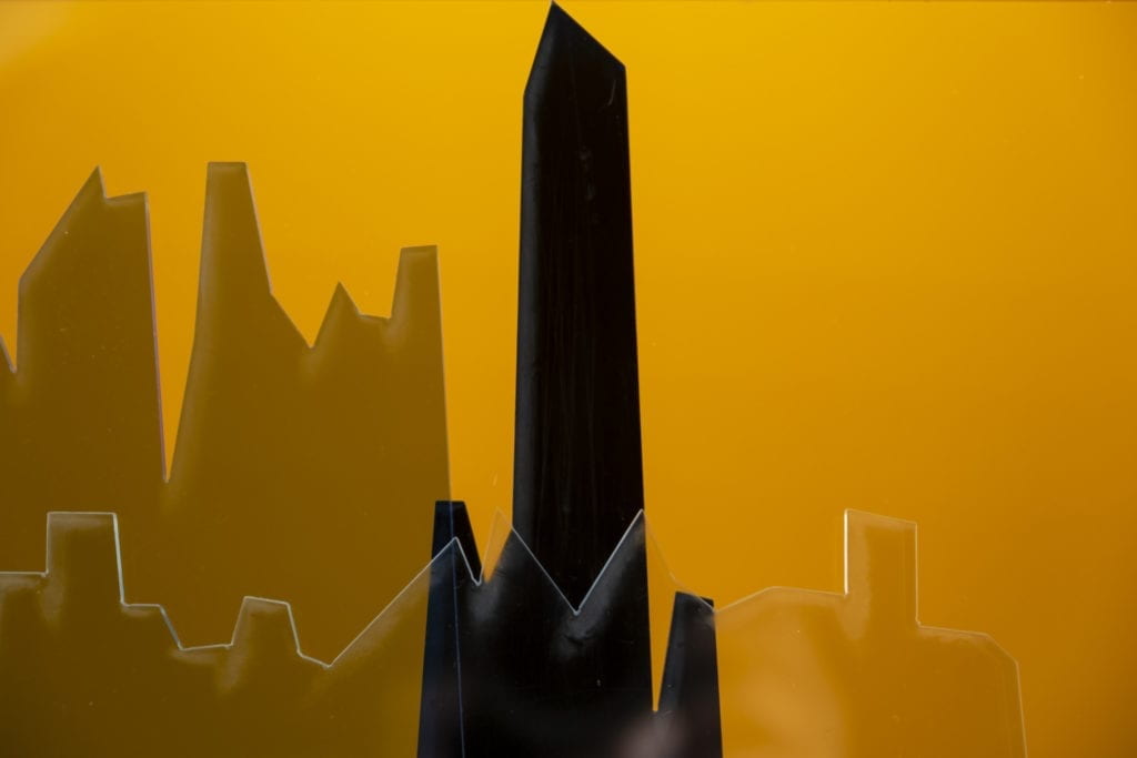
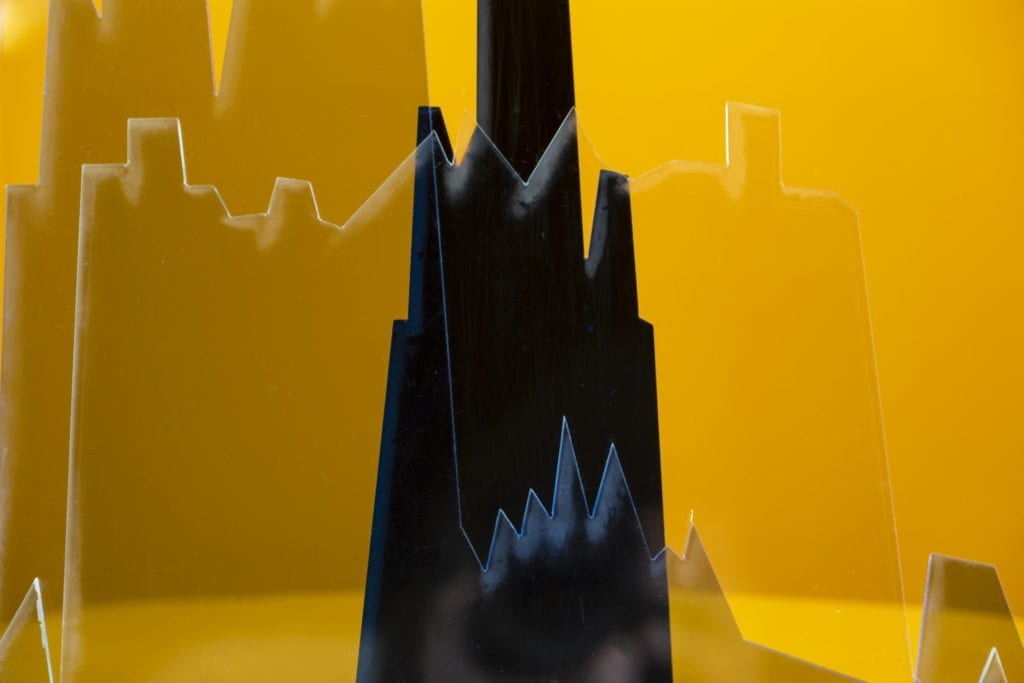
For the final construction, I layered the three-wave diagrams on top of each other and all three on orange backing. 
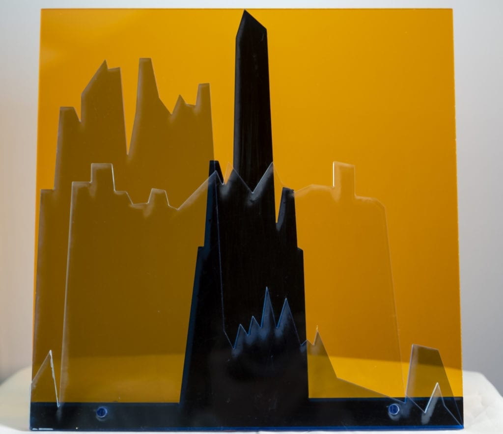
Final Laser Cut Piece

I laser cut a .23 diameter hole through the pieces and pressed an acyclic dowel in to hold the piece together.
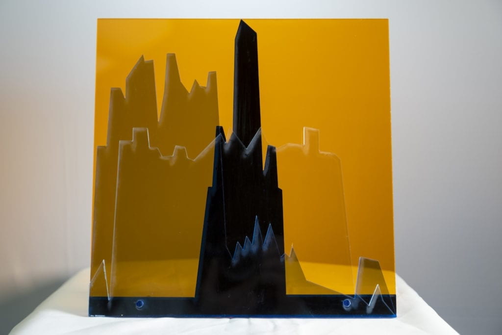
Final Laser Cut Piece

The acrylic dowel was 4 inches long and also acted as a stand for the piece. 
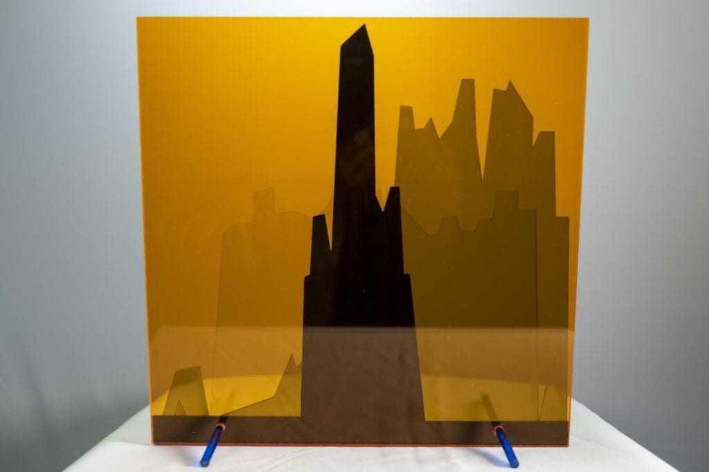
Final Laser Cut Piece

Final Laser Cut Piece

Close up view.

Final Laser Cut Piece

I’m thrilled with how this piece turned out in the end! There are a few things that I would like to consider in future iterations. 

  • Possible build the piece backward – I really like how it looks through the acrylic. 
  • Run a strip of LED lights on the bottom to illuminate the entire piece. 
  • Figure out why the laser cutter leaves a fog around the edge of a cut. 

Version 2:
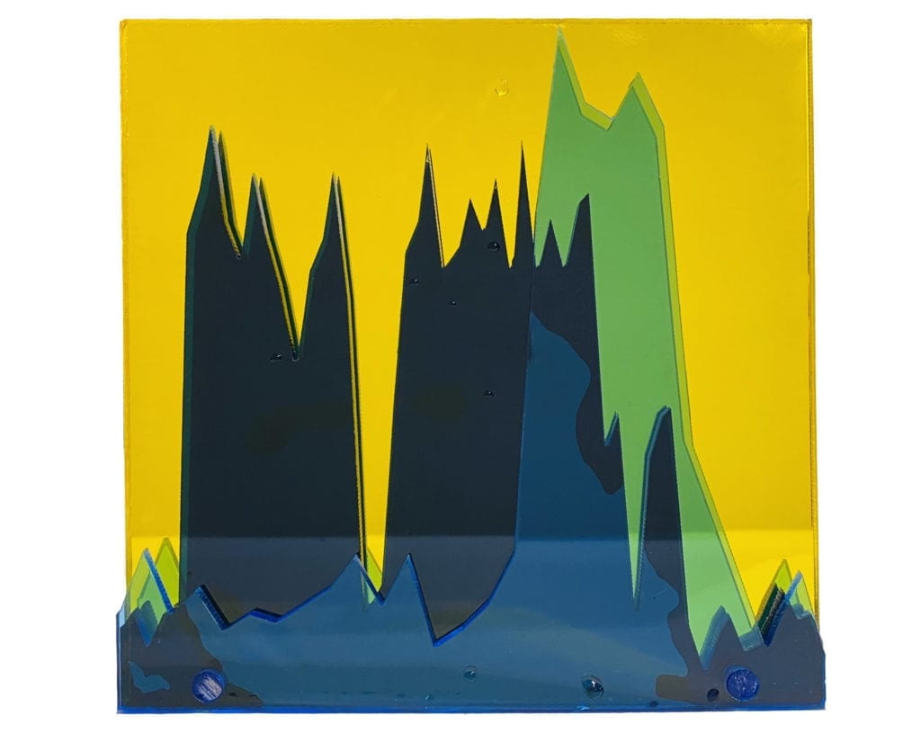
Acrylic waves in blue on a mirrored yellow background Acrylic waves in blue on a mirrored yellow background

PComp Final First Steps

Big steps forward and backward. 

I landed on my final PCOMP project which will record the acceleration of a surfboard on a wave. I will then take this data and produce a physical model of the largest waves the rider surfed in that session. Currently, I have the code for the accelerometer working along with the ability to run the entire board off battery power. 


I can’t for some reason get my SD card reader up and running. I have tried multiple SD card libraries and readers to no avail. Once I get this up and running I will be able to test the system before taking it out in the water. 


Arduino w/ sd chip


Arduino w/ sd chip


SD Chip


Final Assignment Storyboard

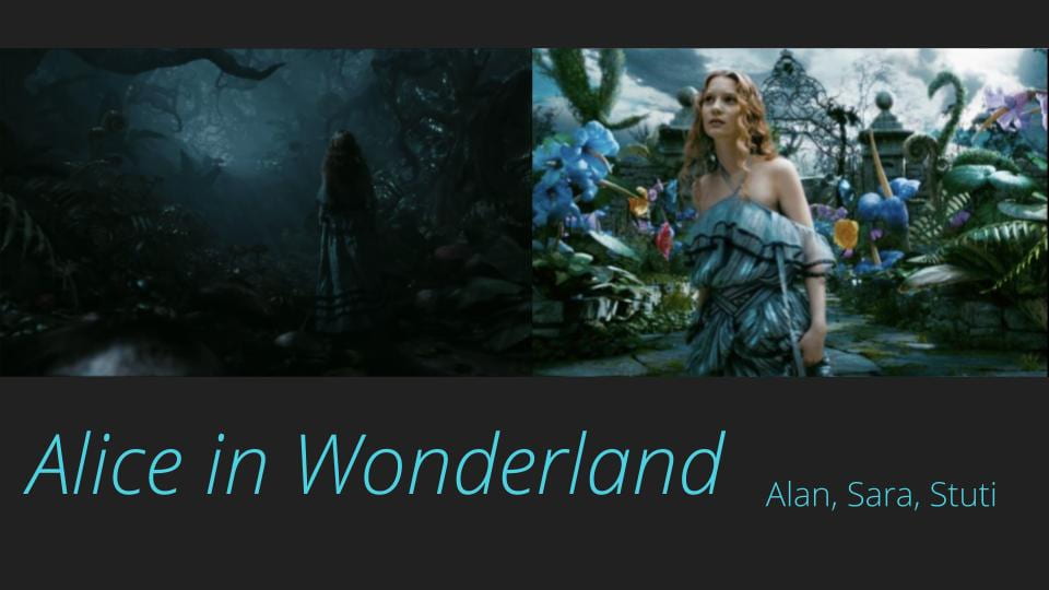
For our final assignment, our group that includes Stuti Mohgaonkar, Sara Ro, and myself decided to create an interactive video installation. We chose to challenge ourselves and design the experience within Unity. All three of us are new to the software but are excited to tackle the task. 

The deck below describes how our world will work. 

Opening slide to a deck on Alice and Wonderland

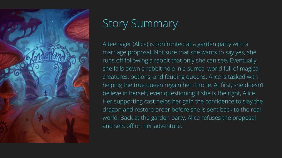
Slide describing the story line of Alice in Wonderland

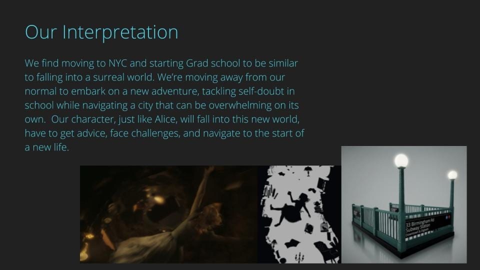
Slide describing out our group will be using Alice in Wonderland as a reference

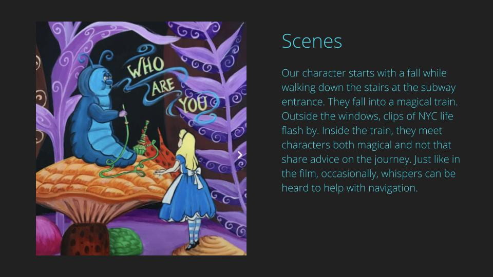
Slide describing the scenes of our Unity walk

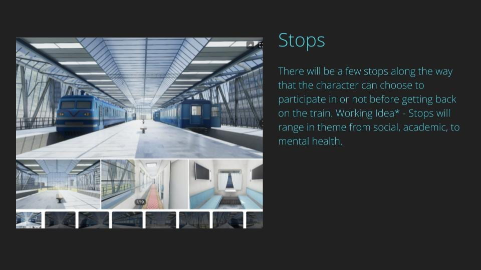
Slide referencing the stops that the magical train will take

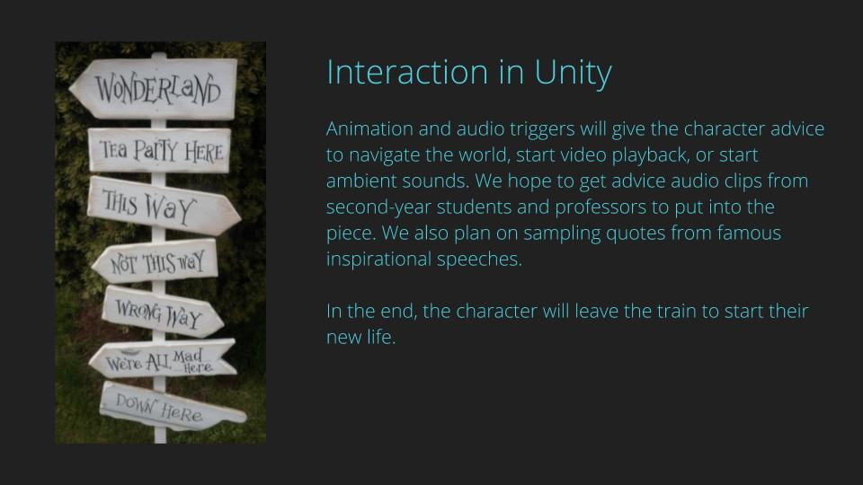
Slide describing how we will use Unity as an interactive tool

Before creating the deck, we watch Ira Glass speak on Storytelling, and we watched the 2010 Tim Burton Alice in Wonderland remake. Both sources gave us inspiration and clarity on how to weave a storyline throughout a narrative. While discussing this project we flagged and are being conscious of how we could easily just focus on creating a visually interesting world without creating the story arc.