Pressure Sensors

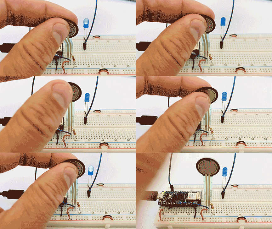
This week’s labs had us build circuits that are activated by some sort of analog input.  I enjoy working with pressure sensors, so I decided to stick with them.

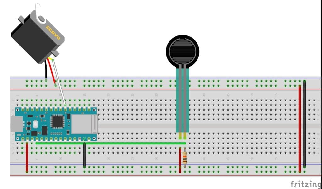
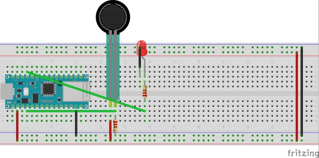
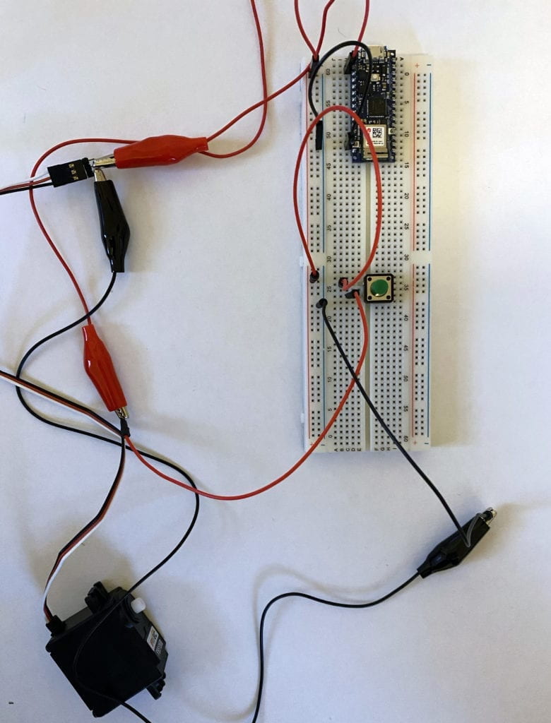
The first lab had me running a servo motor. The wiring and code seemed straightforward, and I was confident that I would get it up and running quickly. Unforchentely, I ran into a problem that I couldn’t explain. The servo wouldn’t turn on. I started my troubleshooting by mapping out the pressure sensor to make sure I was getting a reading. The pressure sensor was working correctly. I checked power to the servo next. I had power. Usually, my problem comes from my code, so I checked and re-checked it. Everything looked to be in order, so I decided to tear apart the circuit and rebuild it. After the rebuild, the servo was still not working. At this point, I needed a break. The next day a few of my classmates troubleshot the circuit with me. Eventually, someone mentioned that the servo might be broken. Quickly we switched it out, and everything worked perfectly. I tried two other servos, and they also worked. Lesson learned. 

Top down sketch of a breadboard layout. A pressure sensor is running a servo.


Video: Servo

The second lab was to run tones through a speaker and control them with sensors. 

Again, I couldn’t get the final device to activate. Power was running to my sensors and the speaker, but no sound was coming out. I thought back to my last lab and tested to see if my speaker was functioning and that my solder was good. Everything checked out. Something had to be wrong with my code. Eventually, I noticed that I had not mapped the sensor range correctly. After correcting for the proper mapping, the speaker worked! A much quicker fix then the servo lab. 

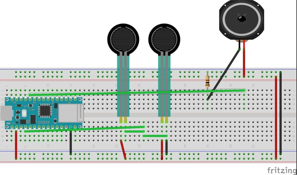
Example 1: Two pressure sensors running a speaker. 

Top down sketch of a breadboard layout. Two pressure sensors running a speaker.

Video: Two pressure sensors running a speaker

Video: “pitches.h” library example

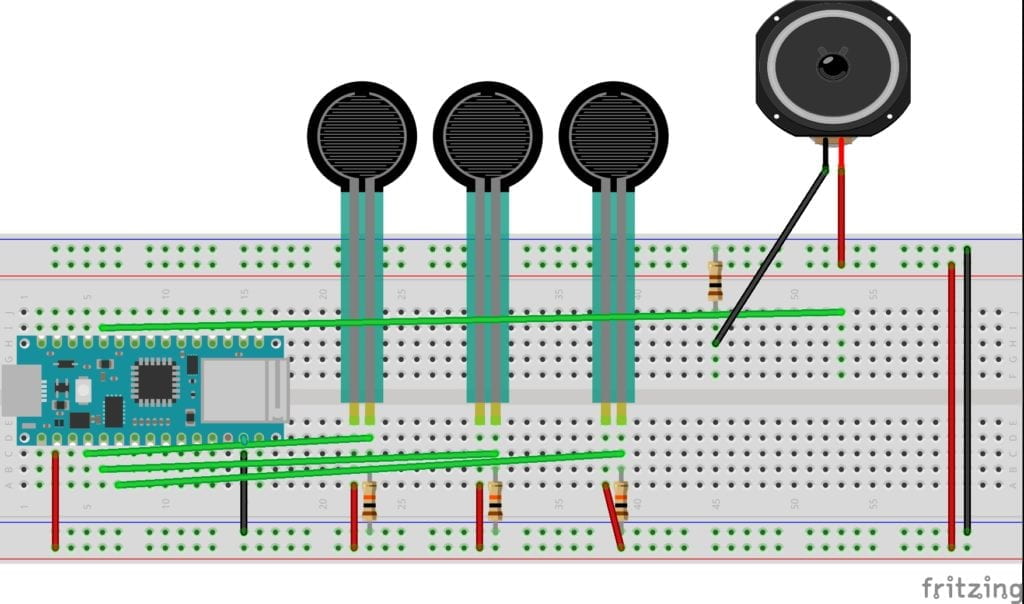
Example 2: Three pressure sensors running a speaker.

Top down sketch of a breadboard layout. Three pressure sensors running a speaker.

Video: Three pressure sensors running a speaker

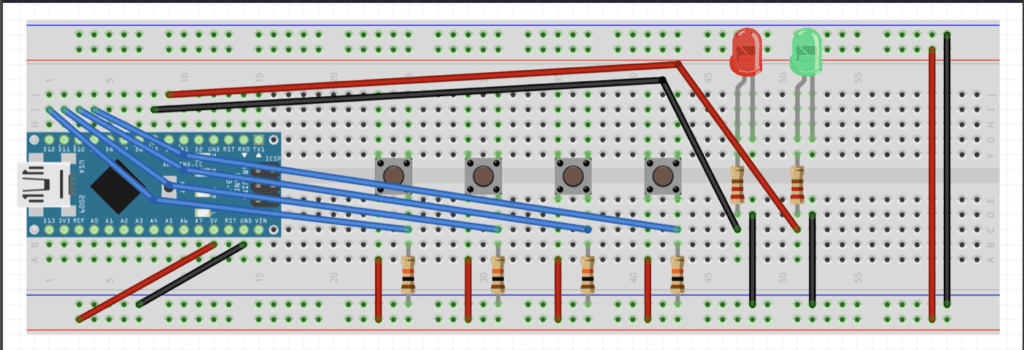
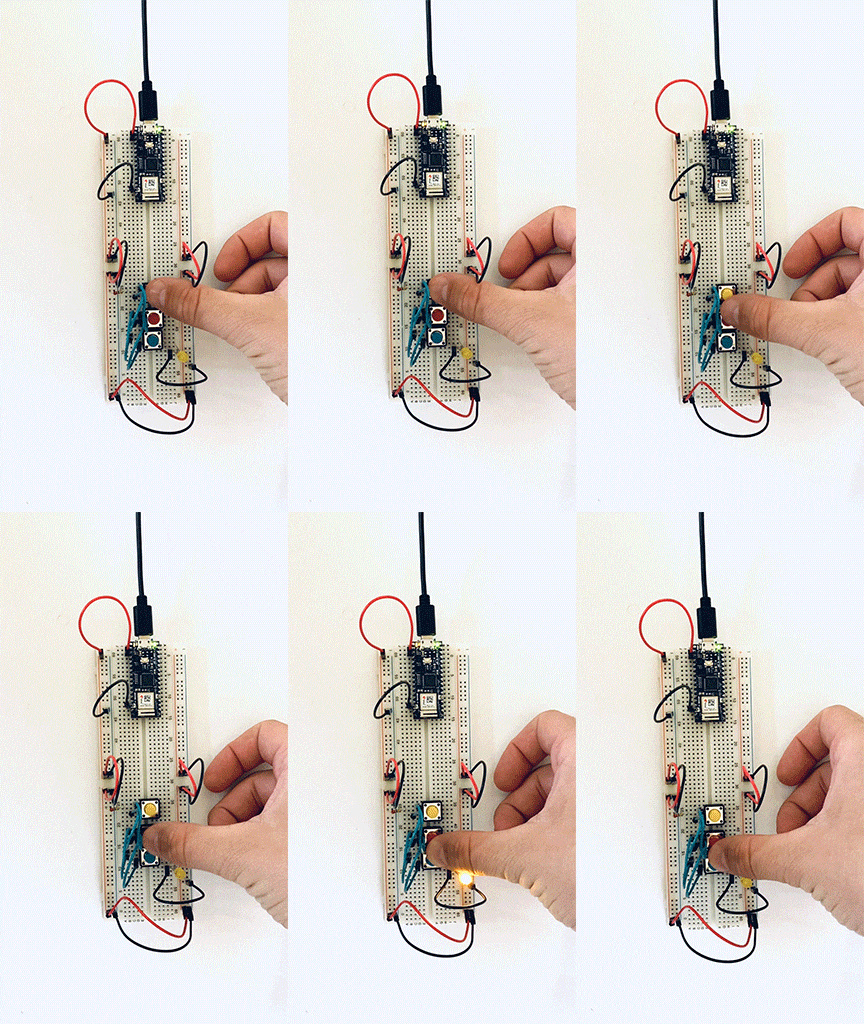
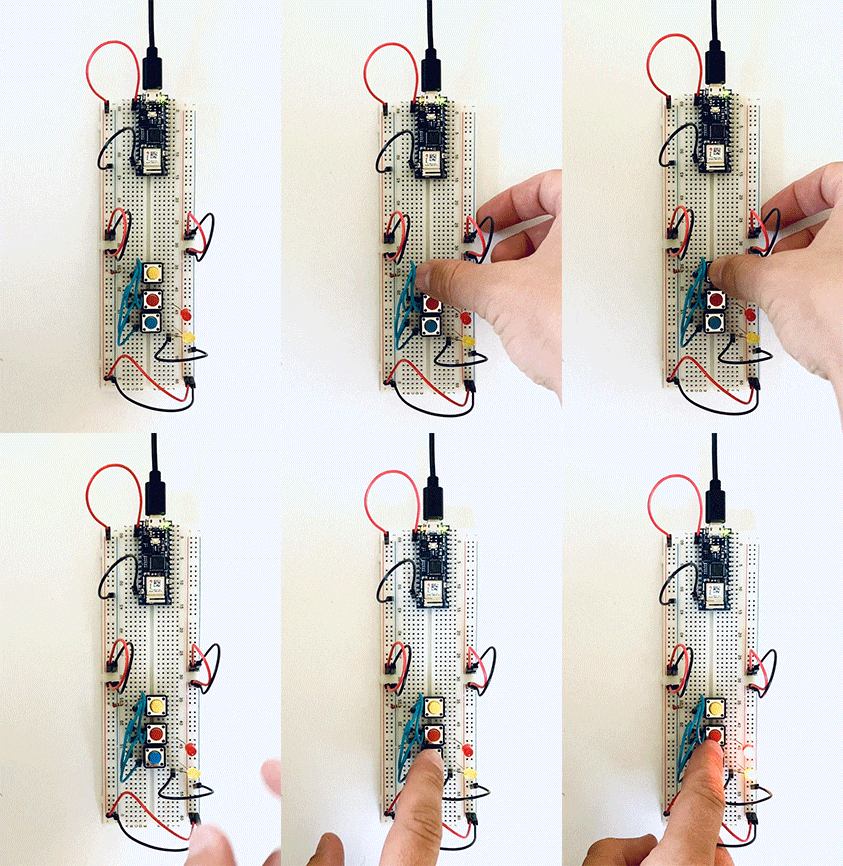
To wrap up this week my partner Stephanie Chen and I started to design our first project. We decided to make a padlock using four buttons. We started researching how to make this happen and developed a basic circuit sketch. We hope to get the circuit running, then change out the controls and build nice housing. 

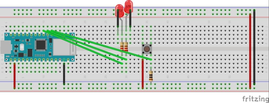
Top down sketch of a breadboard , four switches, 2 LEDS.

Rollover – Button – Slider

This week we were teamed up to “make a rule-based animation that incorporates motion and interaction and includes a user interface element of your design.” Jenny and I collaborated. Luckily we both are working in NYC and could safely meet on the floor to spend an entire day focusing on the project. 

We set out to make a button that when you hover over it, bouncing balls appear on the screen. This undertaking seemed both challenging and executable. We knew that we needed to use if statements to constrict the bouncing balls to the canvas, so we started there.

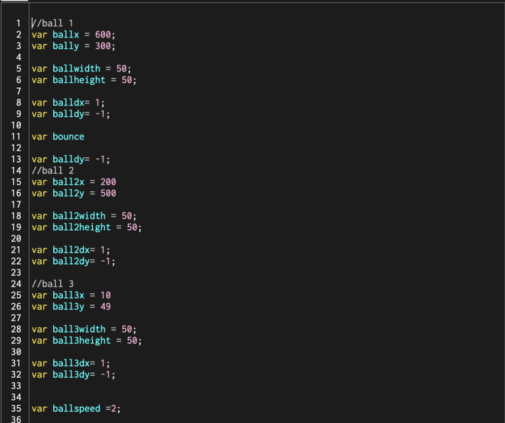
First, we set up all our variables. 
A list of variables in p5js editor.

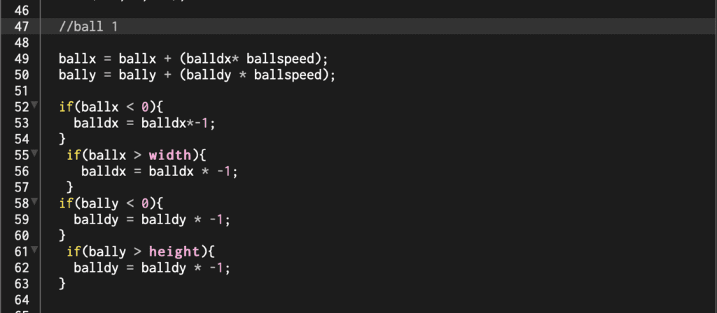
Next, we started writing out our if statements one for each side. We thought that if the ball reached the edge, we would multiple the direction by -,1 reversing it.  This worked great, but the code seemed very long. 

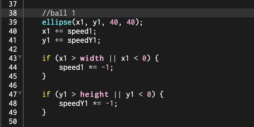
After giving it some thought, we came up with a way to shorten everything down. Instead of writing out an if statement for each side, we used an if statement containing || (or). This modification cut our code down significantly and made it easier to read. p5js sketch using or statements.

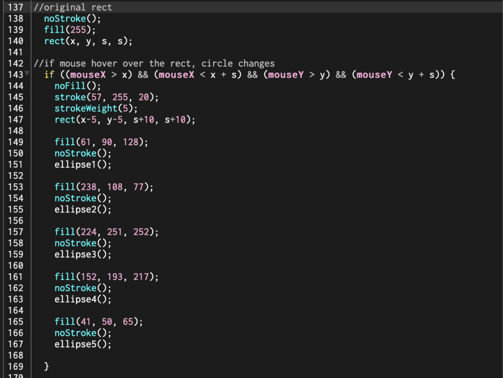
The final step was to make the rectangle that would activate the bouncing balls. 

Mouse activated button on a p5js sketch.

After we completed the sketch we wanted something just a little more dynamic. So we decided to add one more statement which changes ball size back and forth.

p5js sketch show a shifting circle size function.

Click here to see the final sketch. 

I had a great time pairing up on this project. It was fun collaborating, bouncing ideas off each other, and having someone to help troubleshoot. Every week I develop a much deeper appreciation for every button, switch, and component of a computer. 

Final Assignment Storyboard

For our final assignment, our group that includes Stuti Mohgaonkar, Sara Ro, and myself decided to create an interactive video installation. We chose to challenge ourselves and design the experience within Unity. All three of us are new to the software but are excited to tackle the task. 

The deck below describes how our world will work. 

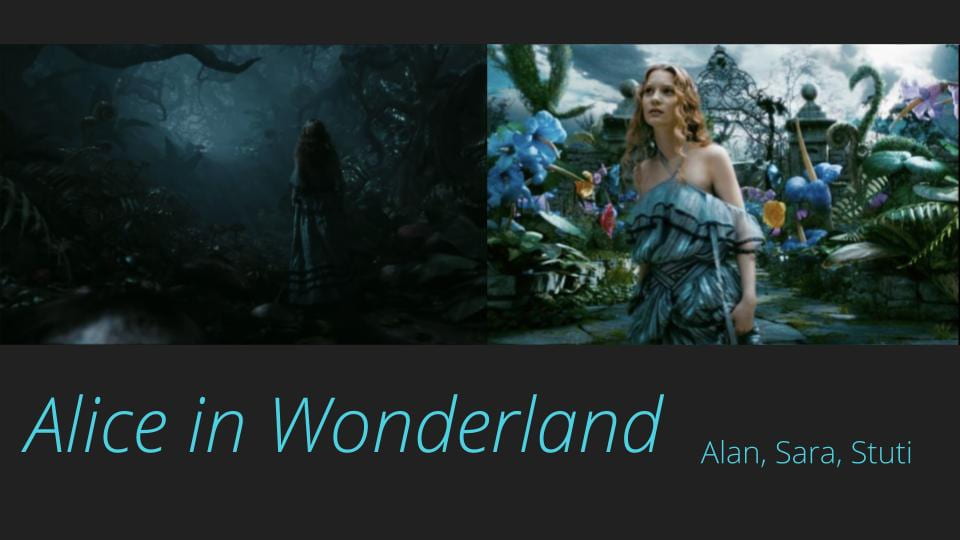
Opening slide to a deck on Alice and Wonderland

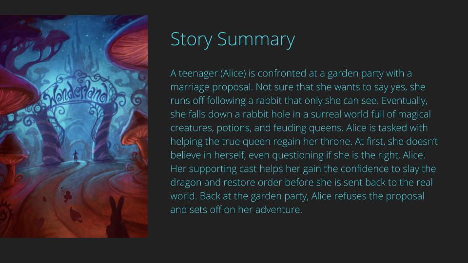
Slide describing the story line of Alice in Wonderland

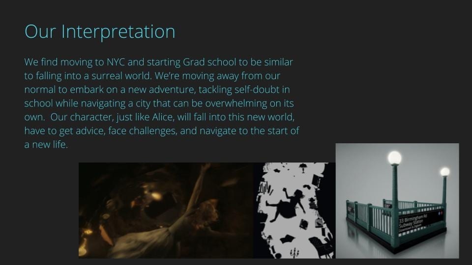
Slide describing out our group will be using Alice in Wonderland as a reference

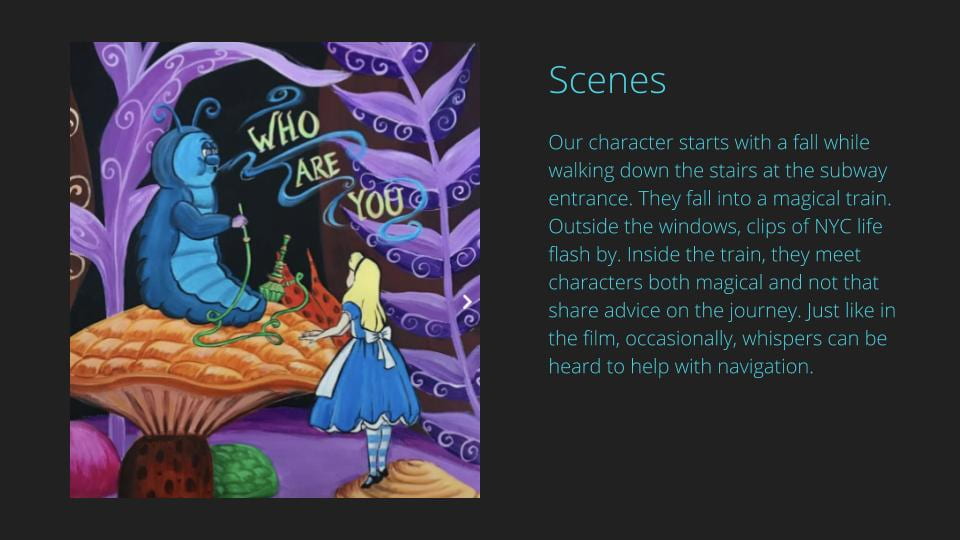
Slide describing the scenes of our Unity walk

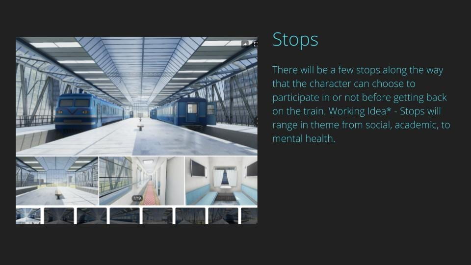
Slide referencing the stops that the magical train will take

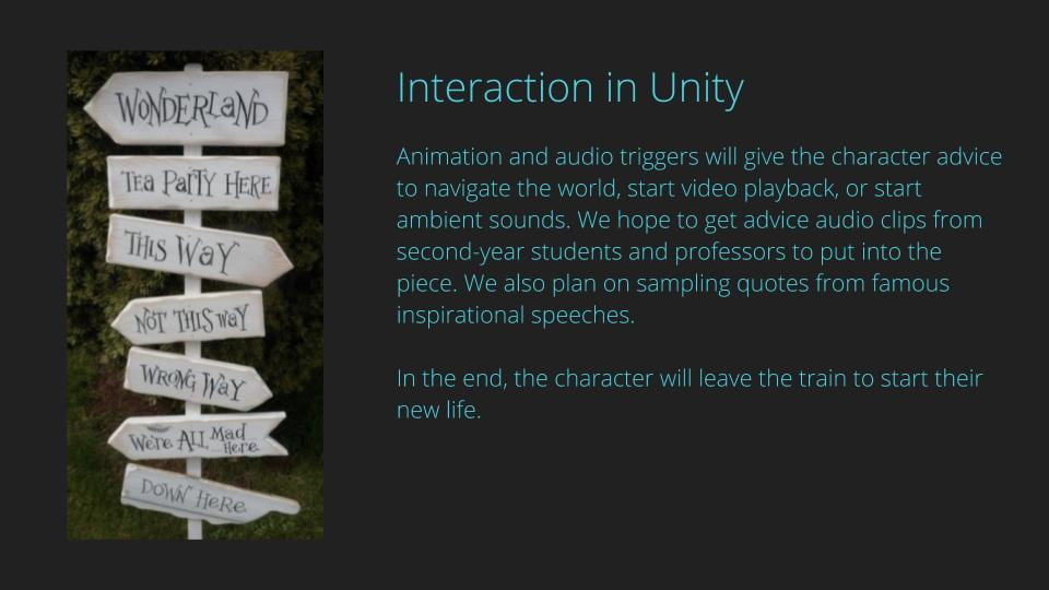
Slide describing how we will use Unity as an interactive tool

Before creating the deck, we watch Ira Glass speak on Storytelling, and we watched the 2010 Tim Burton Alice in Wonderland remake. Both sources gave us inspiration and clarity on how to weave a storyline throughout a narrative. While discussing this project we flagged and are being conscious of how we could easily just focus on creating a visually interesting world without creating the story arc. 

Digital Input/Output – Analog Input

This week we dove into digital input/output and analog input. For most of the assignments, I decided to cut and strip my wire instead of using jumper cables. I found that the jumper cables were too long and made the board turn into a nest of wires. It also looks much nicer!

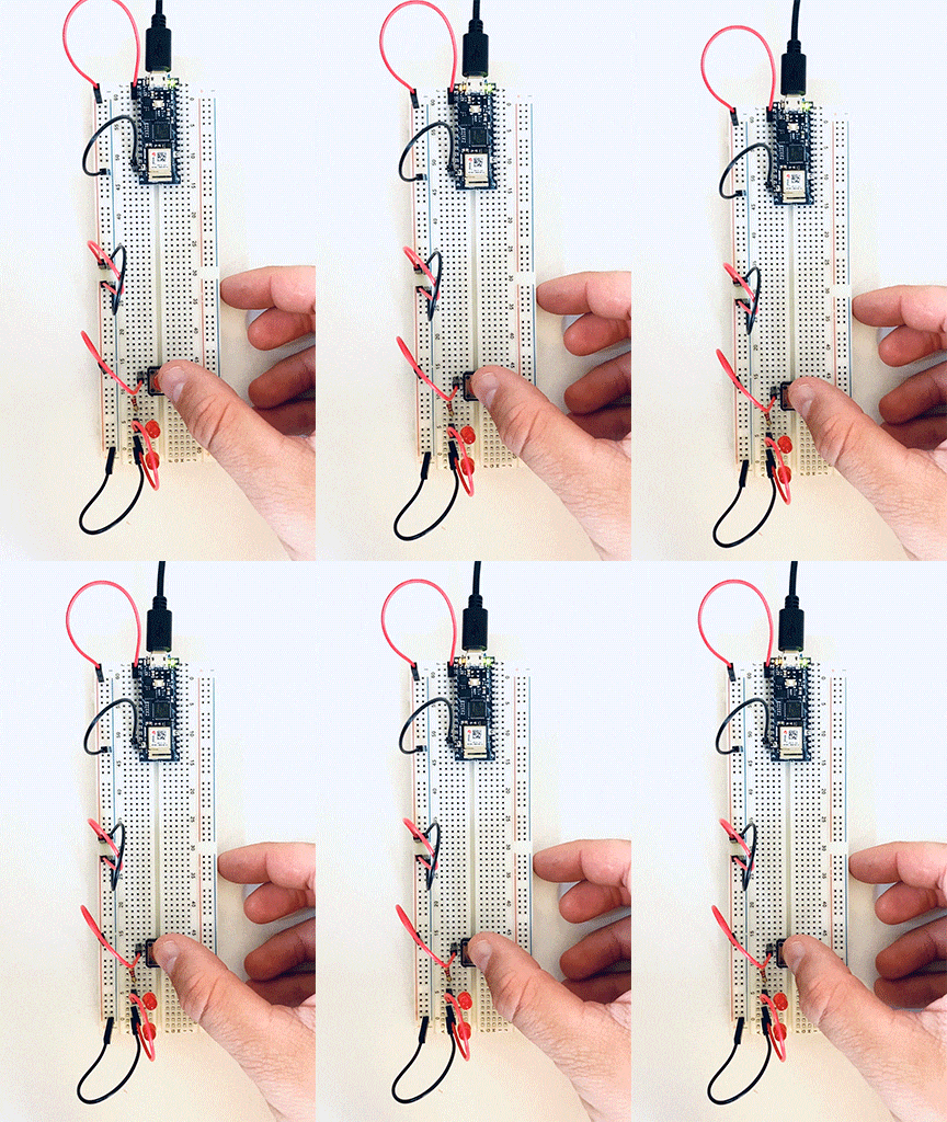
For the first lab, I connected two LEDs to a switch.  This lab didn’t give me much trouble. 

Two LEDs connected to a switch on a breadboard.
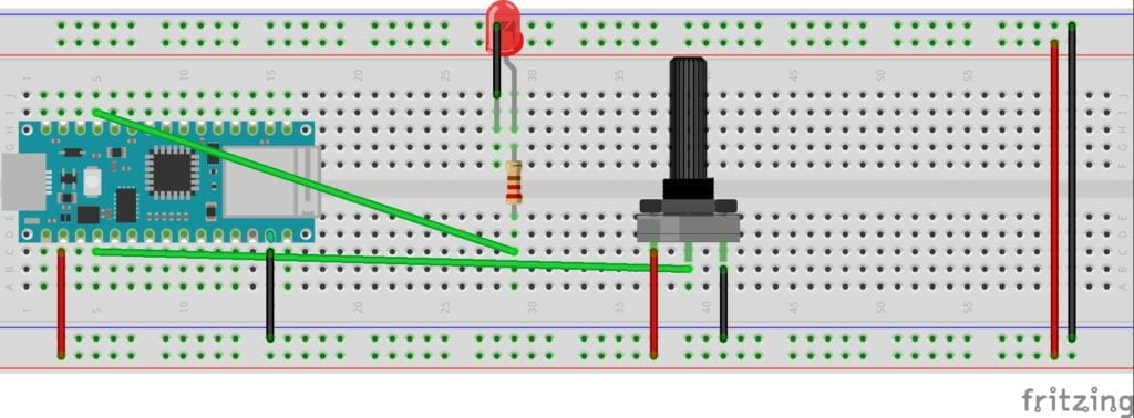
Sketch of two LEDS connected to a switch

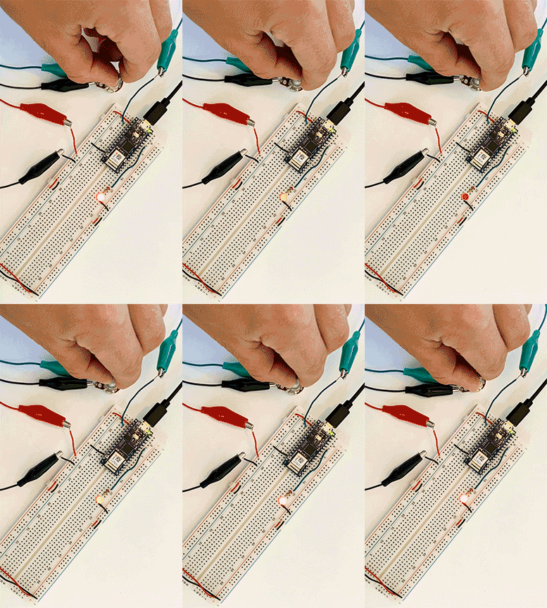
Next, I removed one LED and wired a potentiometer into my breadboard. After putting the new code on the Arduino, everything worked perfectly. 


Potentiometer connected to breadboard lighting up a LED

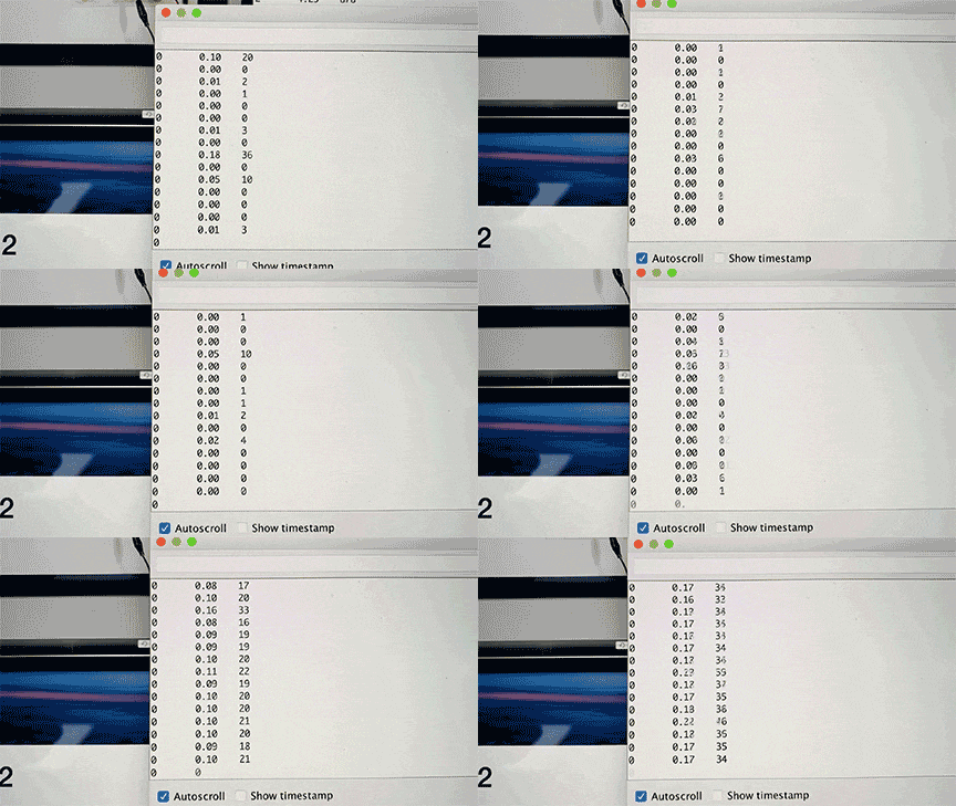
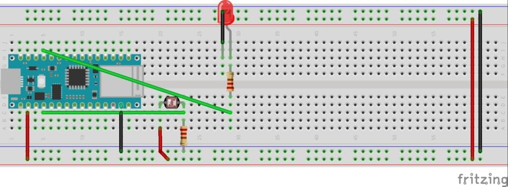
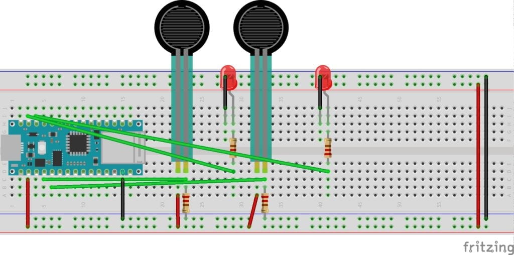
Everything started so well until I moved to the sensors. After wiring the breadboard, I ran the serial monitor in the Arduino software. I was surprised to see a very low reading when I pushed really hard on the pressure sensor or completely blocked the light on the phototransistor. I wire and re-wired the board, tried new sensors, and saw no change. To get the LED to light-up properly, I mapped the sensors and changed their settings based on my low readings. The mapping worked, but I wanted to figure out what was going wrong. In a group office hour, the residents told me to check my resistor. They were correct. I was using a 10 Ω resistor when I should be using a 220. After swapping out the resistor, my sensors worked as expected. I had to remap them with the new readings. I read the color-coding wrong when picking my resistor, a simple error that provided hours of confusion. 

Data being displayed on a computer screen

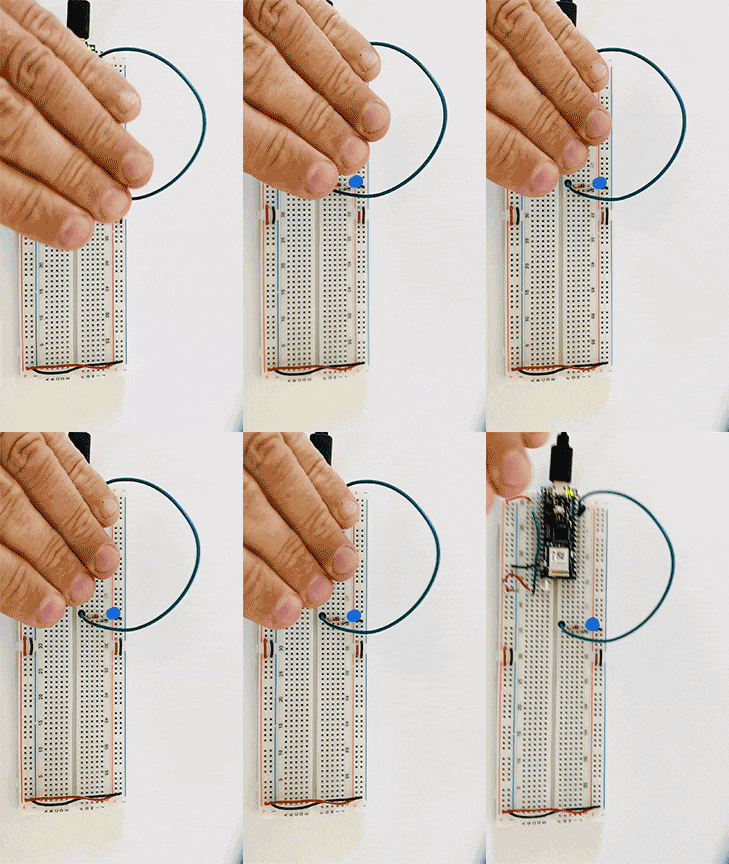
Light sensor used to light a LED Pressure sensor used to light a LED Pressure sensor used to light a LED Light sensor used to light a LED

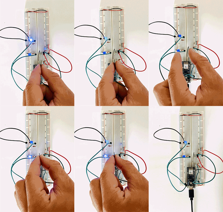
For the final build, I decided to use two pressure sensors and two LEDs. This wiring got fun! And with my new appreciation of testing and measuring my resistors, I was able to get this circuit up and running quickly. I reached out to Danny regarding the blinking of my LED’s when I wasn’t activating the sensor, and he suggested using the constraint command to limit the circuit. I tried coding this, but I couldn’t get it to run. This is my main question for next week’s class. I can see how this extra power could play havoc on a circuit in the future. 

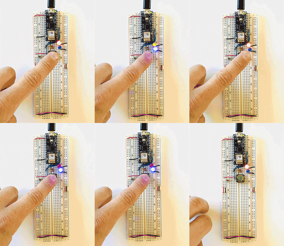
Two pressure sensors lighting up two LEDS on a breadboard. A sketch of Two pressure sensors lighting up two LEDS on a breadboard.


Clock Failure – Character Success

At the start of the week, I had the idea to make a clock. I was concerned that I was biting off more than I could chew but excited to take on the challenge.

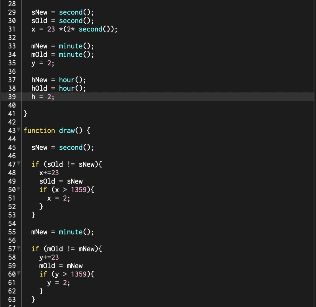
First, I laid out my sketch to have 60-second blocks, 60-minute blocks, and 24-hour blocks. I would call the second, minute, and hour functions to light up the blocks. Using a variable for RGB colors would blick in the current time setting when it advanced, one random color would be left behind. My first problem was the clock wasn’t running. I soon realized that I needed to code some sort of statement to move the rectangle. With the help of Philip Cadoux, I learned IF statements. A sample of that code is below:
Code sample for a P5JS sketch showing an if statement

The clock advanced based on the clock on my computer with a couple of problems. It always reset and didn’t show the proper time. I made a jumbled timer. Lost, I sought out some office hours. I had a great conversation, but we couldn’t come up with a proper solution. After spending a couple more hours on the project, I became frustrated and decided to put this project on hold until I learn more about IF statements and loops. I will come back and complete this sketch!

In the meantime, you can see the current sketch here.

I still wanted to create something this week that uses everything that I’ve learned so far. With a new sketch and idea, I got to work drawing an interactive version of a doodle I’ve drawn for years.  This is Frank, the Gowanus Canal monster. *Gowanus Canal is a highly polluted body of water in Brooklyn that I lived near for years.

Doodle of a monster underwater

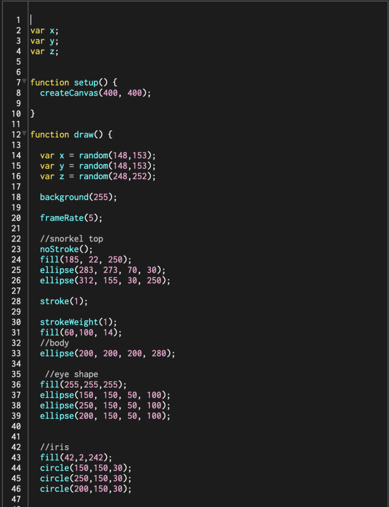
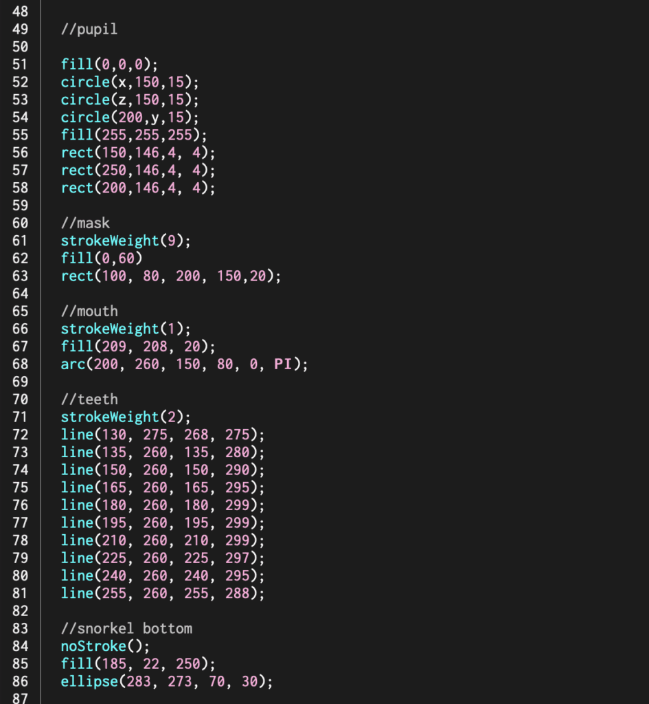
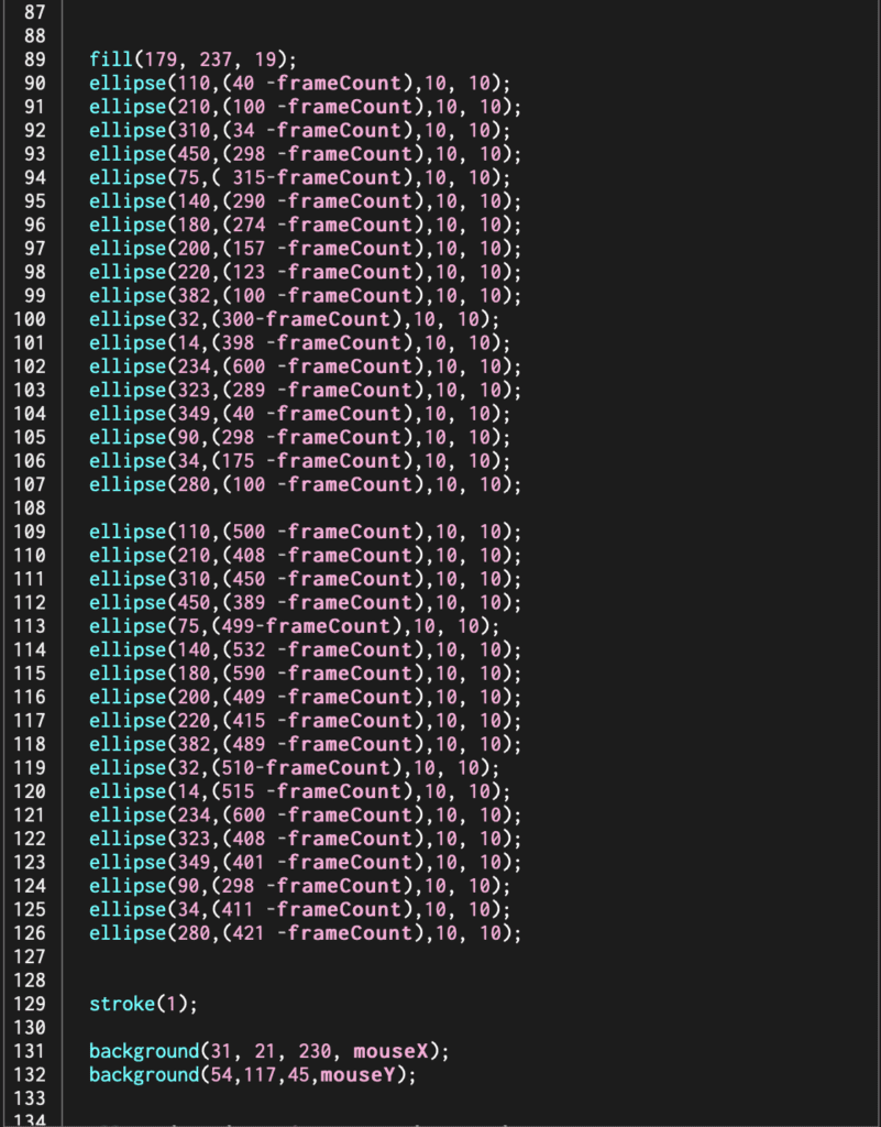
When you play the program, the bubbles rise from the bottom but using -frameCount. Frank’s eyes bounce back and forth that I achieved but using a random variable—finally, the color mix of the water changes based on mouseX and mouseY movements. I used two background settings, one blue and one green, to make the mixing effect. 

Below is the code: 

P5JS sketch

P5JS sketch

P5JS sketch

This sketch isn’t as elaborate as my original clock idea, but it brings me a lot of joy. I tackled some new techniques like mouse movement, variables, and frameCount in a more light-hearted approach. The friends, I sent this to also got a good laugh out of it. Sometimes simple is better, but I will finish that clock!

To see Frank in full glory, head over here. 

Virtual Sound Walk – First Steps In Unity

This week Shannon Hu, David Leyva, and I  collaborated on a virtual sound walk using Unity. The goal was to build a wilderness themed maze using assets from the Unity Store and sound triggers. As the player progresses through the maze, they would encounter various noises triggered by invisible collision frames. Our sounds would be made up of recorded and found clips that we edited in Audition. 

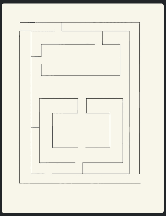
First, we tackled building the maze from a hand-drawn sketch. Line drawing of a maze.

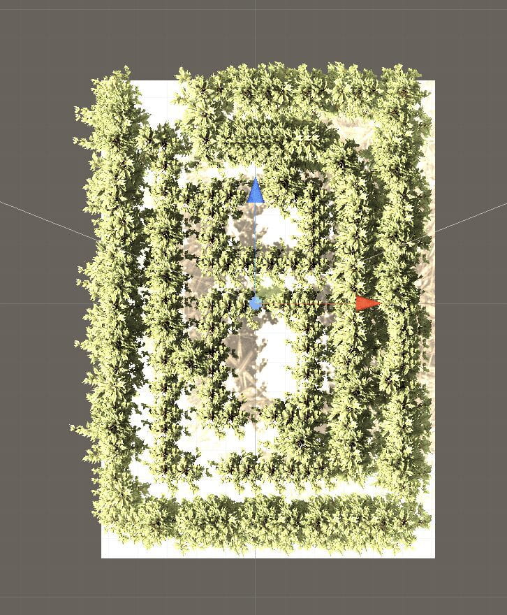
Top down view of a tree maze made in Unity.

We found an asset package that included Redwood tree models that we used as the walls. From this point on, our problems with Unity began. 

  • Character Falling: We found that our character kept falling into the abyss when we hit play. After adjusting for gravity and weight of the character with no visible change, we removed the plane and used a cube as the floor. The cube idea seemed to work, but we’re not entirely sure why. 
  • Stuck Character: Visually, it appeared that we had enough room for the character to navigate the maze, but that wasn’t the case. Every few steps, our character would get tied up on a tree. I need to investigate if there is a way to map out the area that a character can and cannot walk. 
  • Sound Triggers: In our original world, the sounds played on a loop rather than triggered by the character. We later found out that we did not apply the trigger script on the trees. 

The world quickly got confusing to work with, so we deleted most of the assets and started over. 

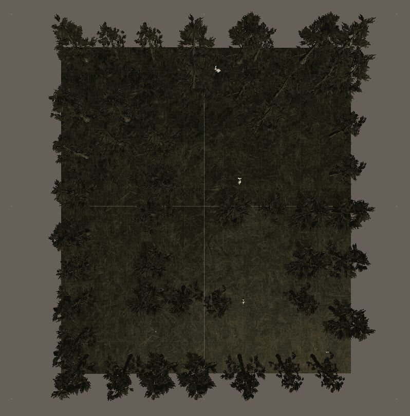
For this second piece, we removed the idea of a maze and scattered trees simulating an old-growth forest of Redwoods. With the triggers adequately placed, the character can experience birds chirping, a wolf howling, bears growling, and a few other surprises. We also were able to import rabbits and birds that a player can find. 

In the end, we would like to add more wildlife and possibly create some creatures. We would also like to make the forest denser without altogether impeding the character from moving. 
Top down view of a unity forest scene. 

Below is a working version of the world uploaded to simmer.io. 

From this exercise, I believe that I started to grasp the basic fundamentals of Unity and look forward to creating more worlds!

Sound Collage and Readings

Sound Collage Study: 

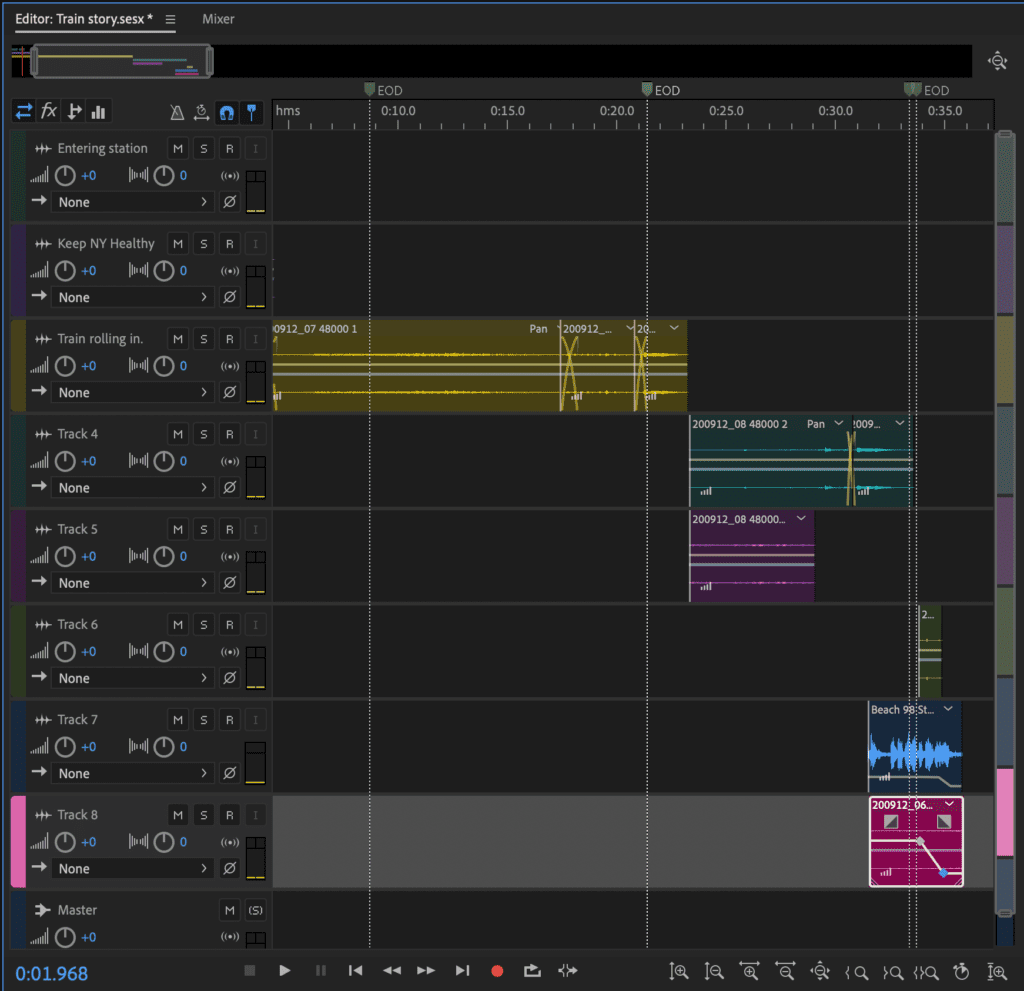
For my first assignment, I made a recording of a subway journey. This past year I haven’t been riding the subway very much at all, which is strange. I got thinking of this assignment, layering sounds, and the subway kept popping into my mind. I wanted to record the familiar sound of the conversations on the train, the clicking of the turnstile, the ding of the closing door, and of course, the screeching of the wheels. Usually, I pop in my headphones and drown out the sound, but I missed them, so I set out for the first time in months to ride the train.  Back home, I used Audition to layer the clips because, just like the rest of NYC, everything is crammed together fitting vying for attention. 

A screen shot of an Adobe Audition file to show the layering of sounds.

I would like to dive deeper into transitions and cleaning up sound. I feel that my audio cuts are far too noticeable. 

____________________________________________

Thoughts on “The Danger of a Single Story”:


I’m moved by novelist Chimamanda Adichie’s TED talk on the harmful impacts of telling a single story. She spoke on how we naturally create stereotypes of other people and cultures by only tuning in or listening to available stories. By not investigating entirely how a culture, country, continent, or person is made up, we go down a path of miscommunication and misunderstanding. This is something that we are all guilty of and need to work harder on understanding to prevent. I appreciate that she shared her own experiences both as a person being stereotyped and as someone who is stereotyping. I don’t believe that single stories are ever going away; instead, everyone needs to learn to identify and openly speak about them. By doing so, we can all get a little better. 
Two of my favorite quotes from the talk are: 
“So that is how to create a single story, show a people as one thing, as only one thing, over and over again, and that is what they become.”

“The single story creates stereotypes, and the problem with stereotypes is not that they are untrue, but that they are incomplete. They make one story become the only story.”

____________________________________________

Thoughts on “The History of Sound Art”:


A History of Sound Art from J Milo Taylor on Vimeo.

This entire composition was challenging to digest. I found myself being removed from the piece entirely during the long stretches of what seemed to be random and disconnected noise samples. To make some sense of the non-speaking sections I started to listen for interesting single sounds and effects that I would like to include in my work. At roughly 12mins 29secs, there is a beautiful scratching sound for example. These individual sounds brought up memories, sparked emotion, and sometimes just sounded interesting. I thought that the comment at 28mins 02 sec “With our whole being we can be responsive to sound. It doesn’t have to be communication of some deep thought.” was fitting for the way I was experiencing the piece. 

Overall, I enjoyed the artist’s explanations of their work and process, for example, the one description of how the performer was scratching, cutting, and distorting records to produce new works. However, I continued to be pulled out when quotes were getting repeated or harsh noises were played over the tops of what they were saying. 


Components – Breadboards – Switches

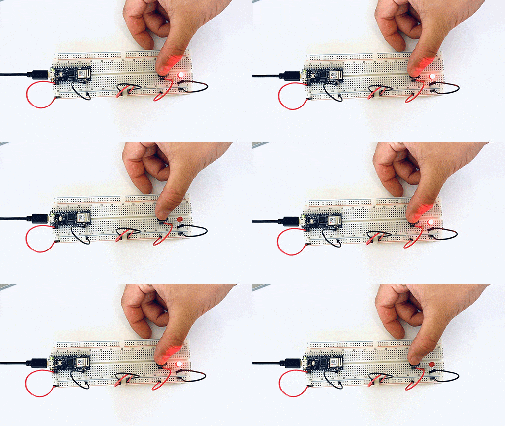
The first set of labs for Physical Computing was all about the basics of electricity, including measuring it, understanding components, terminology, and making simple circuits like lighting an LED and using switches. I was eager to jump into the building after reading and watching all the necessary materials. 

My first simple circuit was a huge success. 

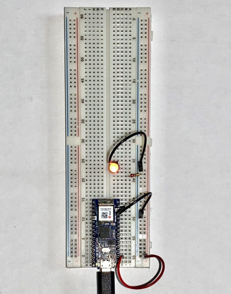
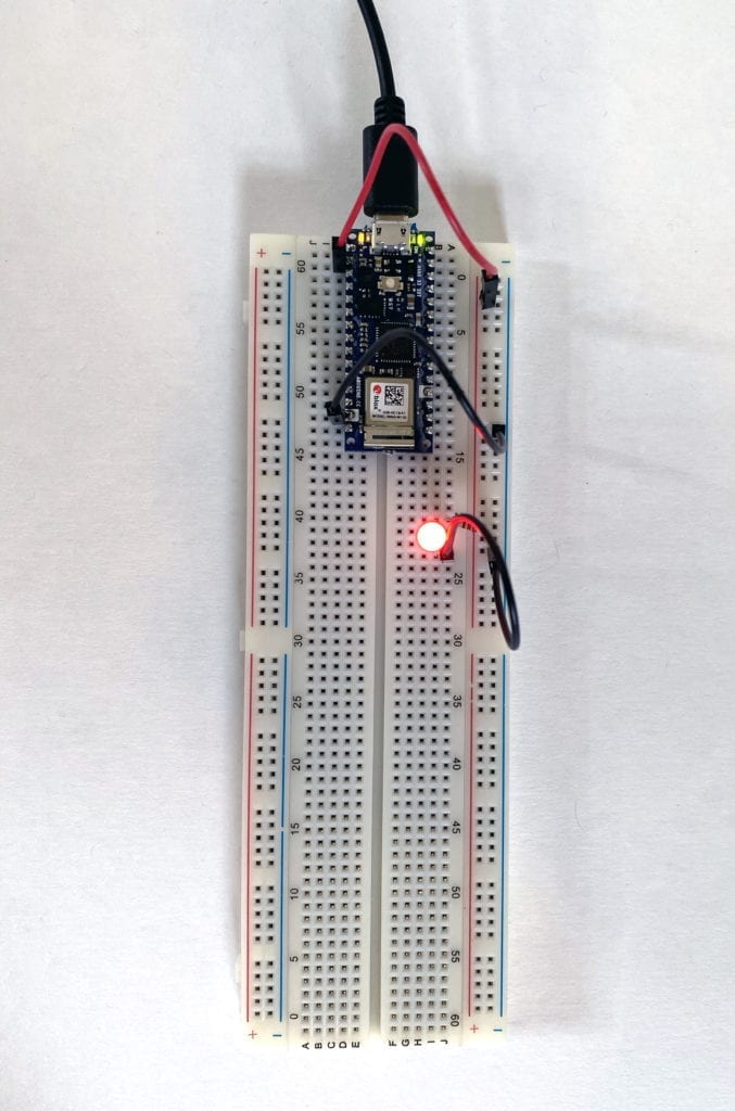
A simple circuit lighting up one LED.

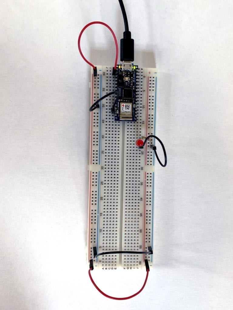
I soon ran into a problem with my second circuit. I attempted to move the LED to the other side of the Breadboard. I thought if I connected jumper wires at the bottom from the left side to the right, it would work correctly. It didn’t.

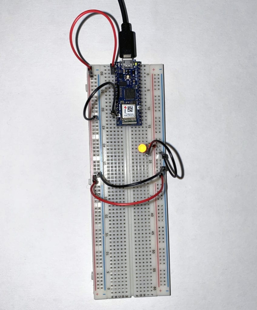
A failed circuit with the LED not lit up.

I started to experiment by removing the lower jumper cables and plugging the power and ground to the same side as the LED. Success! I now knew the Breadboard worked, and I was doing something wrong. 

A simple circuit lighting up one LED.

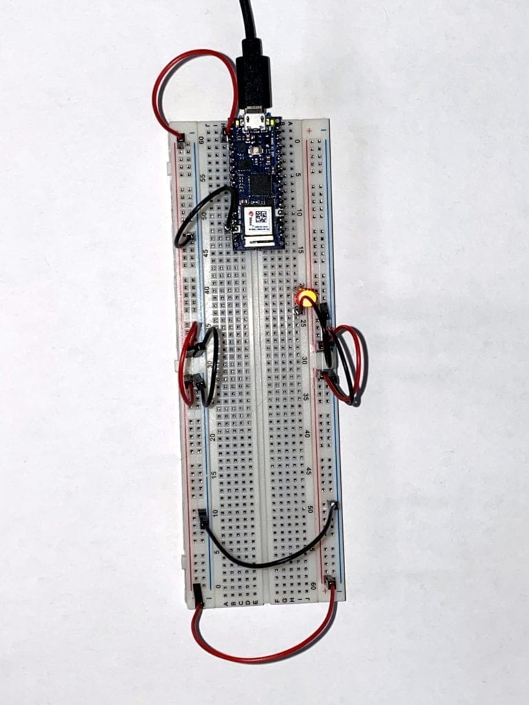
After looking at the Breadboard a little longer, I noticed a larger gap at hole 30 on both the left and right sides. I had a feeling that the + and – columns were not connected all the way. To test this, I moved the power and ground back to the left side and used jumper cables at hole 29, connecting the sides. Success again!

A simple circuit lighting up one LED.

Armed with this new insight, I tried to connect the Breadboard entirely around. Success! 

A simple circuit lighting up one LED.

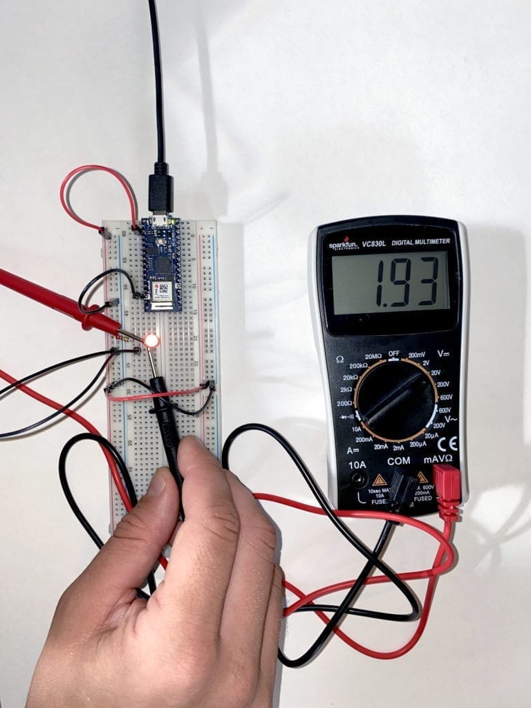
Feeling more confident, I moved on to the next section of the Lab that had to do with measuring currents. 

An image of a multimeter measuring the current running to and LED on a breadboard.

Then to switches and adding components in a series to see how the power would or would not be diminished. 

A gif of a breadboard wired with one switch and one LED.

As I continued to add components in a series, I noticed a voltage a luminance drop throughout the circuit. 

A breadboard wired with a switch and two LEDs in a series.However, when I place the LEDs in parallel, I didn’t see the drop in power or luminance. 
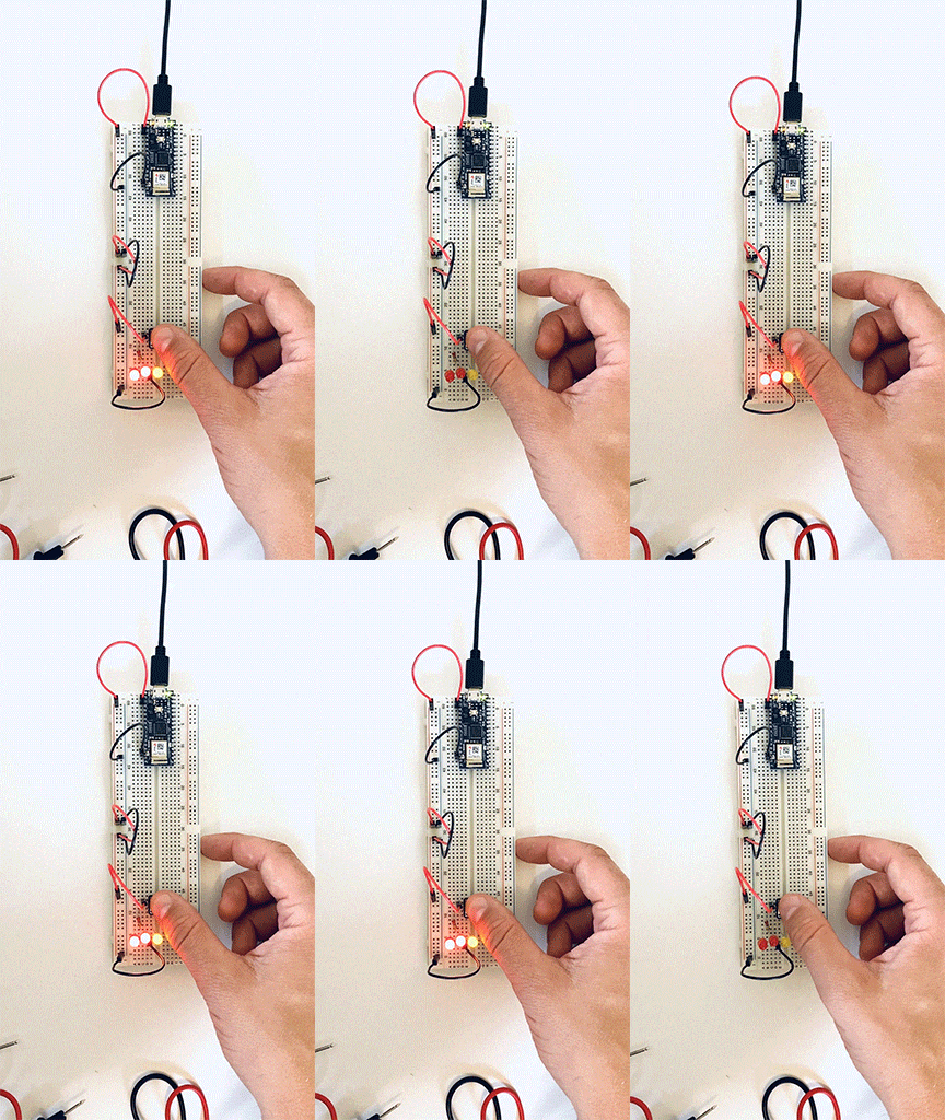
A gif of a breadboard with a switch and three LEDs wired parallel.

Next, I moved on to measuring variable voltage by using a potentiometer. There was a constant power reading between the two side points, but when I measured between a side point and the middle point, there was a change depending on how much I turned the wiper.

A gif of a breadboard wired to a potentiometer and a LED.

I then moved on to working with switches first in parallel than in a series. This first switch, I had to wire three times before I got the circuit correct. 

A gif of breadboard with three buttons and two LEDs. The switches are wired in parallel.

Another example of three switches in parallel, but this time, I added a second LED. 

A gif of breadboard with three buttons and two LEDs. The switches are wired in parallel.

Three switches in a series. The user needs to activate all three switches to complete the circuit. 

A gif of a breadboard wired with three buttons in a series with one LEDHere I placed one independent switch and two in a series on the same circuit. 
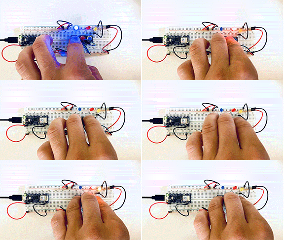
A gif of a breadboard wired with three buttons and three LED's, two buttons are in a series one is independent.

My attempt to add a motor failed. I don’t fully grasp the signal wire and believe that it needs to be coded into the Arduino. I spoke to some of my classmates, and they confirmed this.

I’m looking forward to investigating this more to get it up and running. 

Failed attempt to wire motor into a breadboard with a switch.

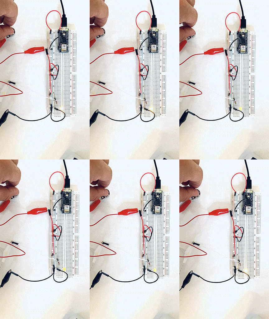
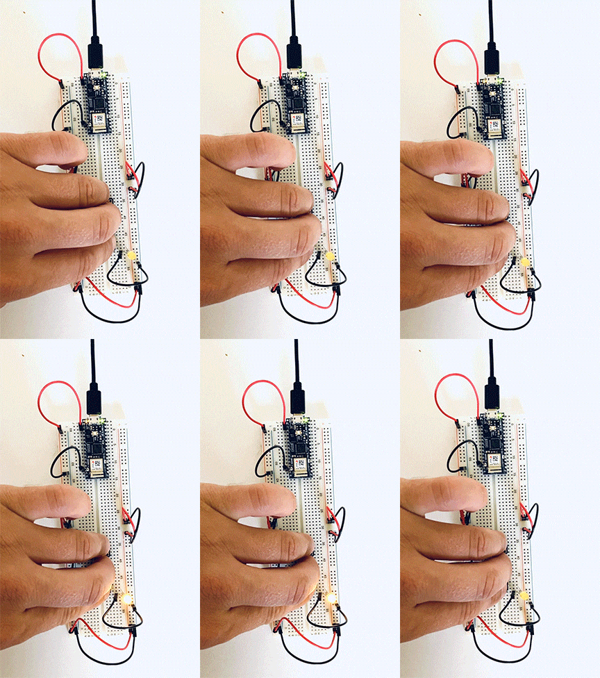
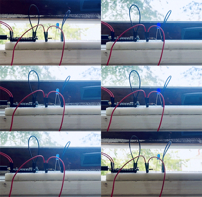
To wrap up the labs, I made a custom switch – The Window Switch; when the window is closed, the LED lights up. 

A gif of a breadboard and an LED wired to a window.


p5js – Self Portrait and Looking Ahead

Being completely new to coding, I was unsure how to start my first assignment, making a sketch using primitive shapes and color tools. After watching the tutorials and reading all the documentation, I knew I had to jump in, make a ton of mistakes, and learn by trial and error. The p5js reference documentation quickly became my friend.

The first problem I encountered was understanding how the X-axis and Y-axis worked. Frustrated on how to lock down locations, I started to research online. Eventually, I stumbled upon a former ITP student blog post on this very assignment.

Vidia spoke about how she found an Image Map Generator site that would plot the drawing’s edge coordinates. I played around on this site for a while but couldn’t get it to work; I would like to explore it more once I have more experience under my belt.

Back to my sketch, I started placing shapes and moving them around to get a better grasp of coordinates. Since I was drawing a face and wanted symmetry, the second feature fell into place much quicker.

The next problem I struggled with for a long time was producing an arc. I couldn’t wrap my head around how to specify the angles in radians. With a little research, I found if I placed. angleMode(DEGREES); at the beginning of my sketch, I could work in degrees instead of radians, which made a lot more sense to me.

The final problem I encountered was working in the proper order. I originally drew the entire sketch and waited to color and remove strokes at the end. Quickly finding out that color was applied to everything below.

Final Note: I found that organization and notes are essential. I ended up breaking each section of the face-up with comments so I could go back later and make corrections.

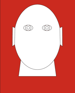
Rough Draft Sketch:

The first rendition of my sketch. The face only contains eyes and pointed ears and is completely white set on a red background.

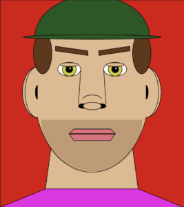
Final Sketch:

My final sketch a complete face set on a red background. The mans face has a light beard and is wearing a green hat and purple shirt. He also has brown hair and green eyes.

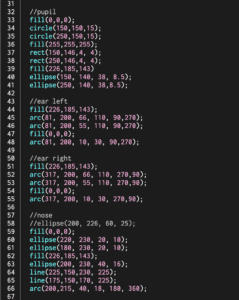
Code Example:

An example of my final sketch code.

My final code: Assignment 1

This exercise has got me thinking about the types of projects I would like to work on this term. I have been working as a photographer during my entire career and have always been drawn to public art and interactive art. The two main reasons I like this style of work is because, for one, I find public art more disarming and accessible. Two, I find that interactive work gets a level of engagement, both active and passive, that static art doesn’t.

In the past, I would have to hire developers to help me achieve my vision. Eventually, this would work, but it came with a host of problems, including:
1) I would have to secure more grant funding to cover the costs of bringing on help.
2) Without proper training, I only had a basic understanding of the technologies available and how to work with them. This left me feeling that I wasn’t pushing my work as far as I could.

This term, I am looking forward to grasping the necessary computation skills to make me a better teammate and explore new techniques to create more dynamic public art.

My work has been focused primarily on putting visuals to scientific research. I would like to continue down this track but also make purely visual pieces this term. For these reasons, I think I’m particularly drawn to these three pieces:

HintFM : Wind Map
Jill Hubley: NYC Trees
TeamLab: Universe of Water Particles Falling from the Sky