The first set of labs for Physical Computing was all about the basics of electricity, including measuring it, understanding components, terminology, and making simple circuits like lighting an LED and using switches. I was eager to jump into the building after reading and watching all the necessary materials.
My first simple circuit was a huge success.
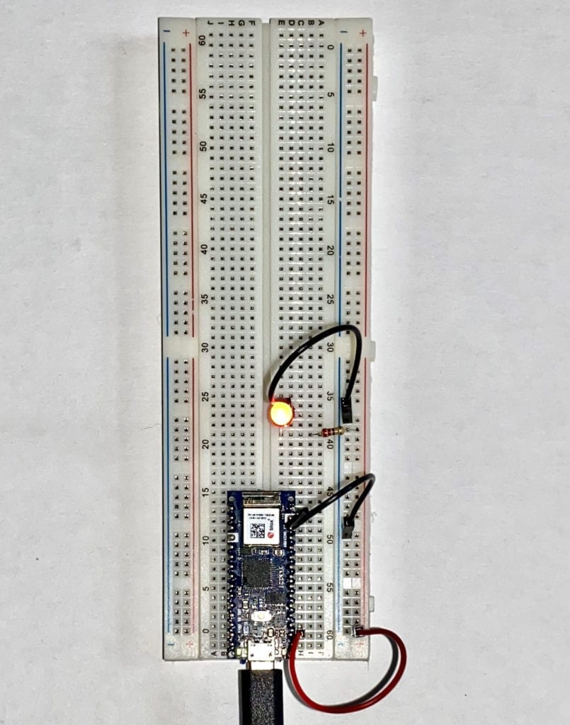
I soon ran into a problem with my second circuit. I attempted to move the LED to the other side of the Breadboard. I thought if I connected jumper wires at the bottom from the left side to the right, it would work correctly. It didn’t.
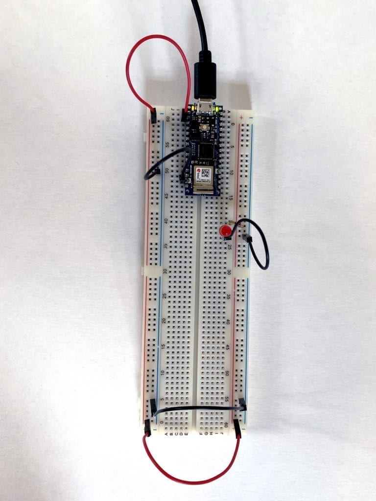
I started to experiment by removing the lower jumper cables and plugging the power and ground to the same side as the LED. Success! I now knew the Breadboard worked, and I was doing something wrong.
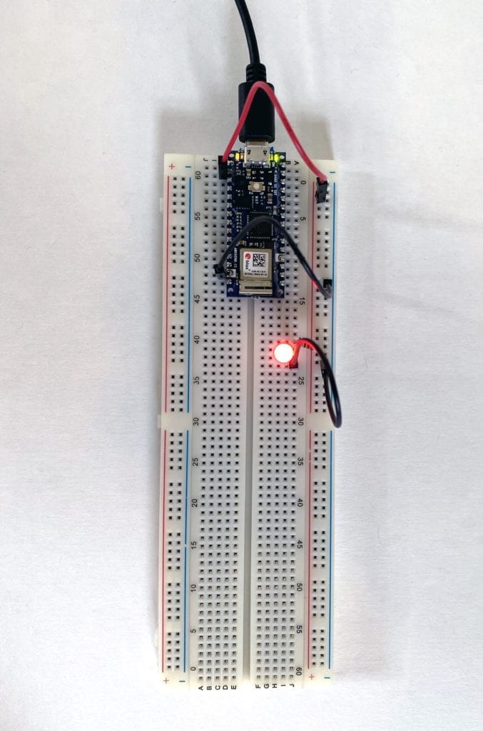
After looking at the Breadboard a little longer, I noticed a larger gap at hole 30 on both the left and right sides. I had a feeling that the + and – columns were not connected all the way. To test this, I moved the power and ground back to the left side and used jumper cables at hole 29, connecting the sides. Success again!
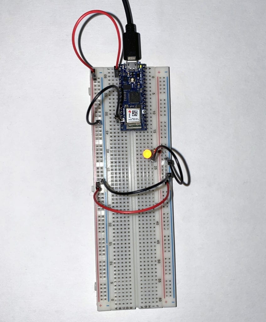
Armed with this new insight, I tried to connect the Breadboard entirely around. Success!
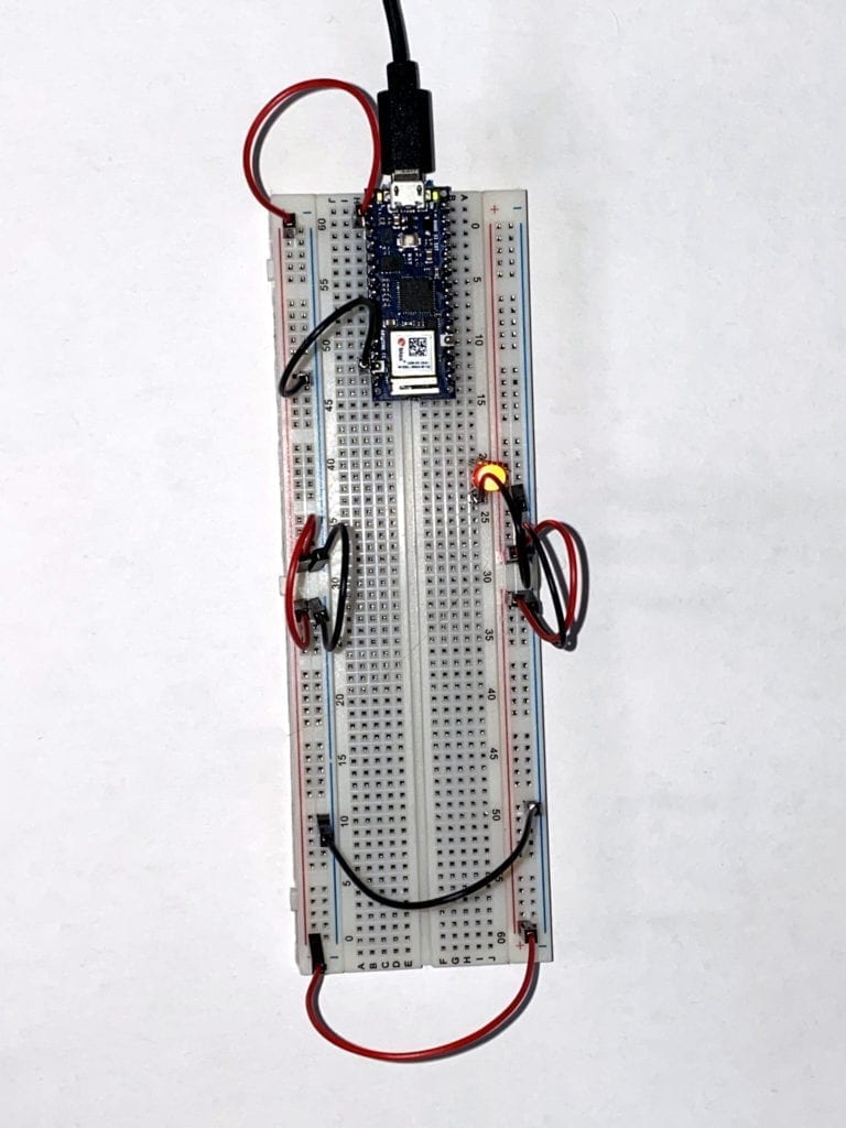
Feeling more confident, I moved on to the next section of the Lab that had to do with measuring currents.
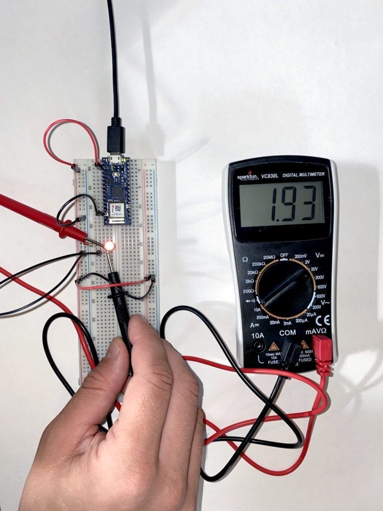
Then to switches and adding components in a series to see how the power would or would not be diminished.
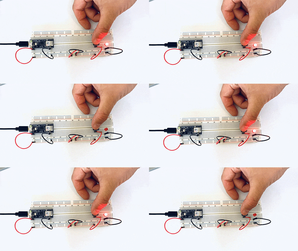
As I continued to add components in a series, I noticed a voltage a luminance drop throughout the circuit.
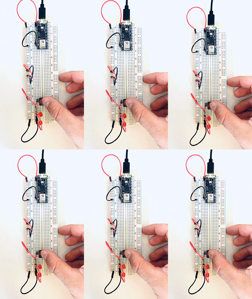 However, when I place the LEDs in parallel, I didn’t see the drop in power or luminance.
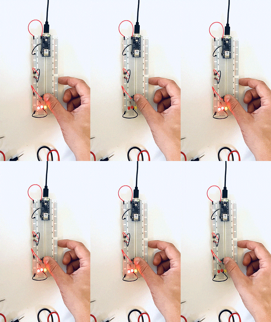
Next, I moved on to measuring variable voltage by using a potentiometer. There was a constant power reading between the two side points, but when I measured between a side point and the middle point, there was a change depending on how much I turned the wiper.
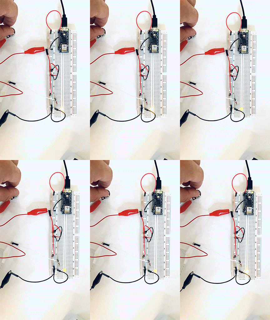
I then moved on to working with switches first in parallel than in a series. This first switch, I had to wire three times before I got the circuit correct.
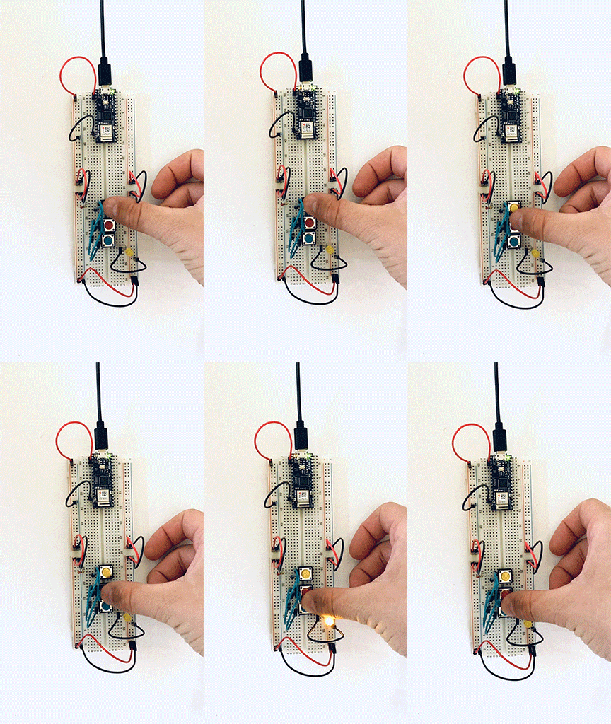
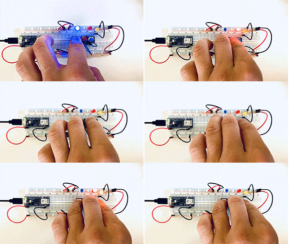
Another example of three switches in parallel, but this time, I added a second LED.
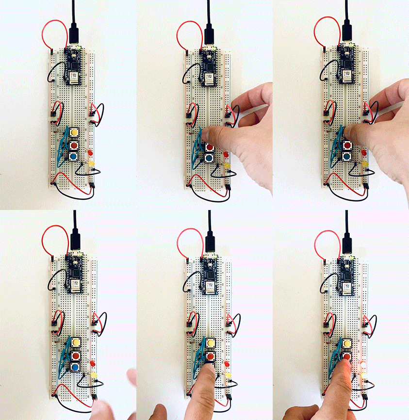
Three switches in a series. The user needs to activate all three switches to complete the circuit.
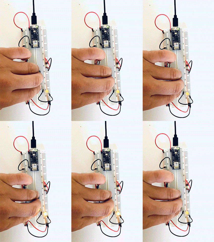 Here I placed one independent switch and two in a series on the same circuit.
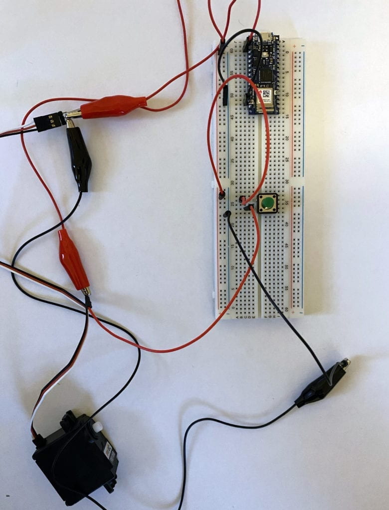
My attempt to add a motor failed. I don’t fully grasp the signal wire and believe that it needs to be coded into the Arduino. I spoke to some of my classmates, and they confirmed this.
I’m looking forward to investigating this more to get it up and running.
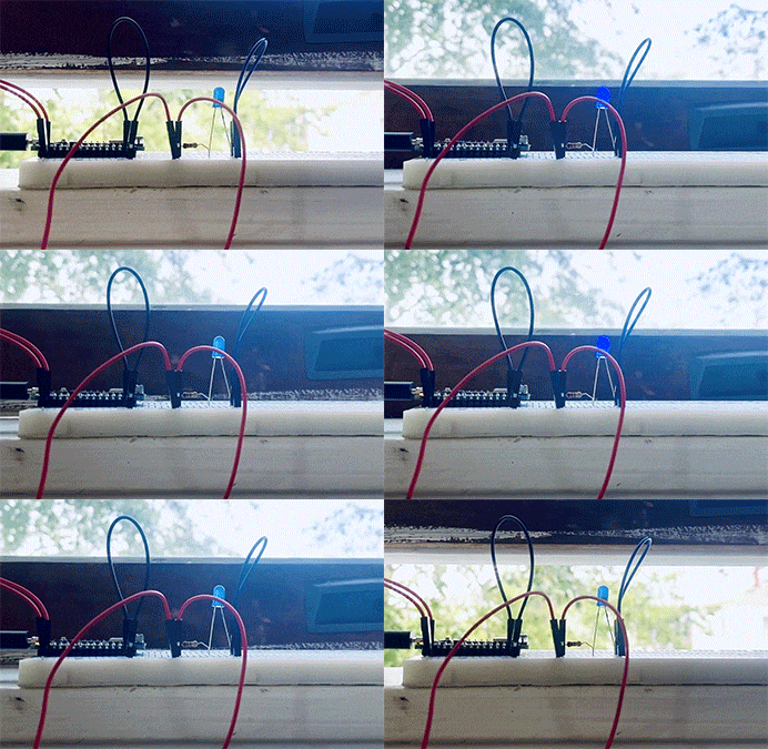
To wrap up the labs, I made a custom switch – The Window Switch; when the window is closed, the LED lights up.
