Digital Input/Output – Analog Input

This week we dove into digital input/output and analog input. For most of the assignments, I decided to cut and strip my wire instead of using jumper cables. I found that the jumper cables were too long and made the board turn into a nest of wires. It also looks much nicer!

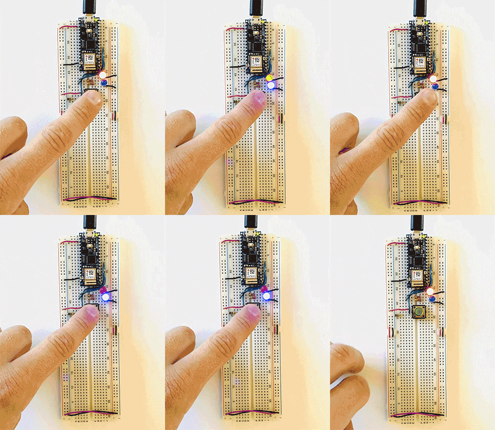
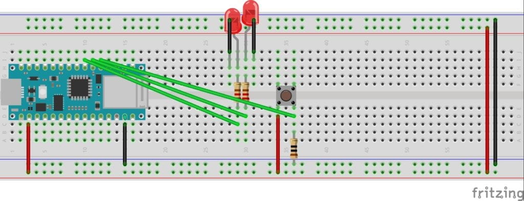
For the first lab, I connected two LEDs to a switch.  This lab didn’t give me much trouble. 

Two LEDs connected to a switch on a breadboard.
Sketch of two LEDS connected to a switch

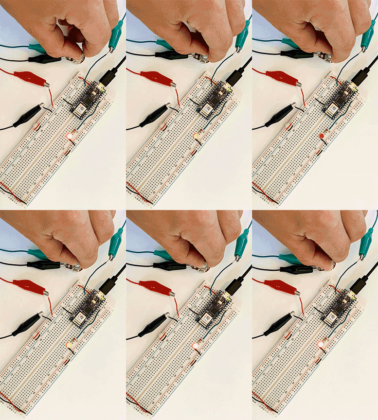
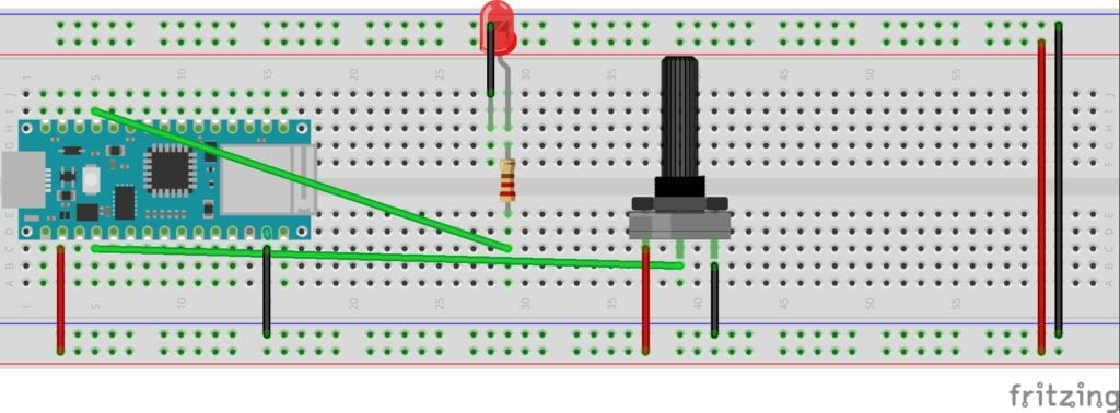
Next, I removed one LED and wired a potentiometer into my breadboard. After putting the new code on the Arduino, everything worked perfectly. 


Potentiometer connected to breadboard lighting up a LED

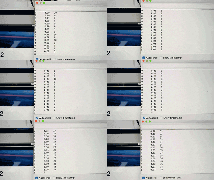
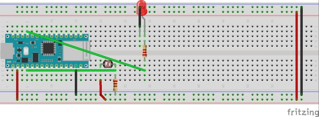
Everything started so well until I moved to the sensors. After wiring the breadboard, I ran the serial monitor in the Arduino software. I was surprised to see a very low reading when I pushed really hard on the pressure sensor or completely blocked the light on the phototransistor. I wire and re-wired the board, tried new sensors, and saw no change. To get the LED to light-up properly, I mapped the sensors and changed their settings based on my low readings. The mapping worked, but I wanted to figure out what was going wrong. In a group office hour, the residents told me to check my resistor. They were correct. I was using a 10 Ω resistor when I should be using a 220. After swapping out the resistor, my sensors worked as expected. I had to remap them with the new readings. I read the color-coding wrong when picking my resistor, a simple error that provided hours of confusion. 

Data being displayed on a computer screen

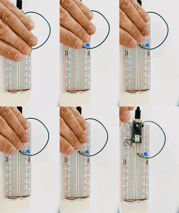
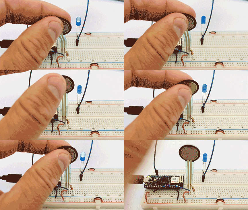
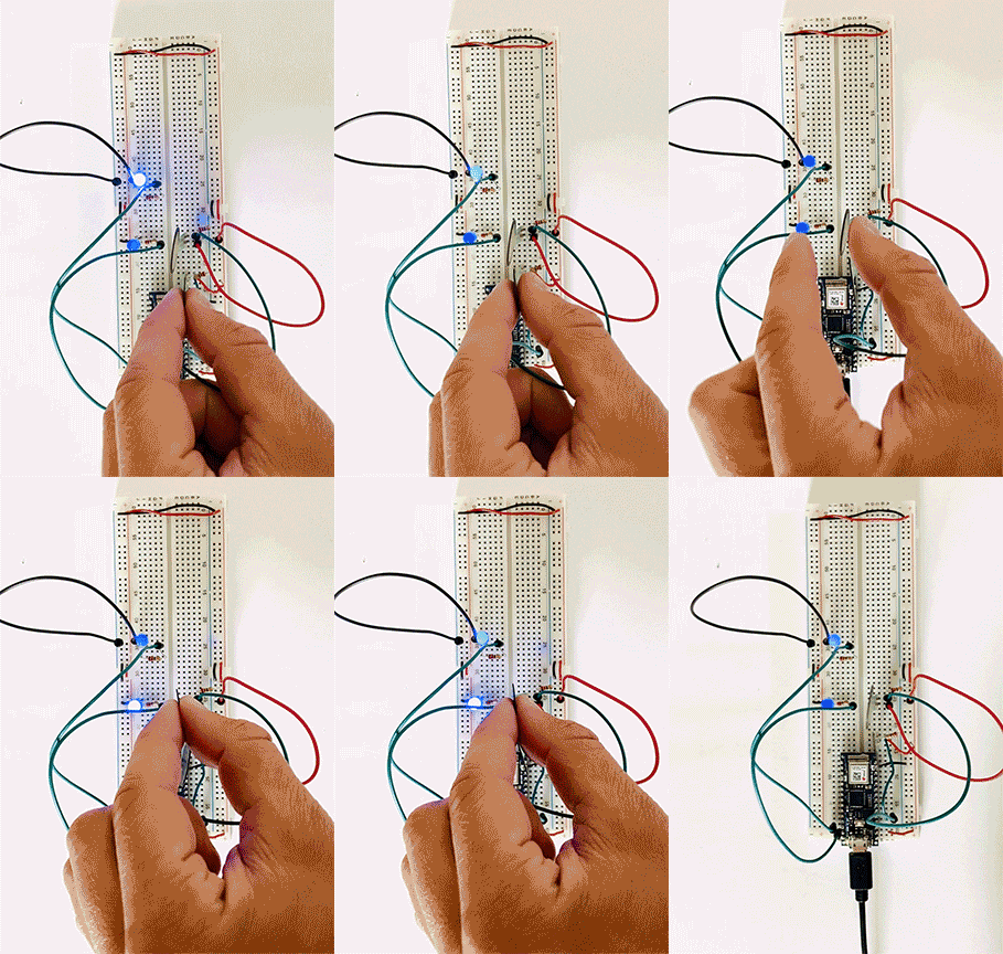
Light sensor used to light a LED Pressure sensor used to light a LED Pressure sensor used to light a LED Light sensor used to light a LED

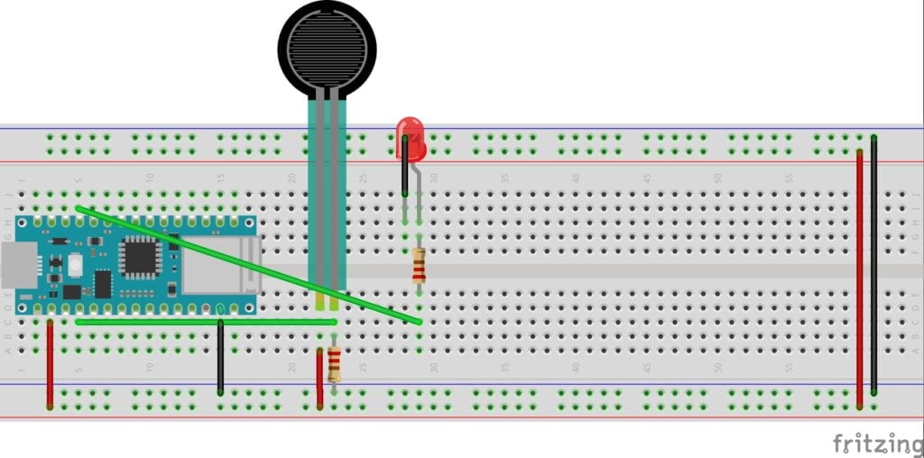
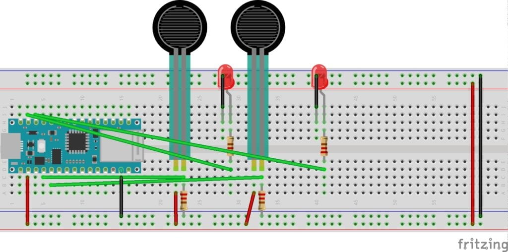
For the final build, I decided to use two pressure sensors and two LEDs. This wiring got fun! And with my new appreciation of testing and measuring my resistors, I was able to get this circuit up and running quickly. I reached out to Danny regarding the blinking of my LED’s when I wasn’t activating the sensor, and he suggested using the constraint command to limit the circuit. I tried coding this, but I couldn’t get it to run. This is my main question for next week’s class. I can see how this extra power could play havoc on a circuit in the future. 

Two pressure sensors lighting up two LEDS on a breadboard. A sketch of Two pressure sensors lighting up two LEDS on a breadboard.


Components – Breadboards – Switches

The first set of labs for Physical Computing was all about the basics of electricity, including measuring it, understanding components, terminology, and making simple circuits like lighting an LED and using switches. I was eager to jump into the building after reading and watching all the necessary materials. 

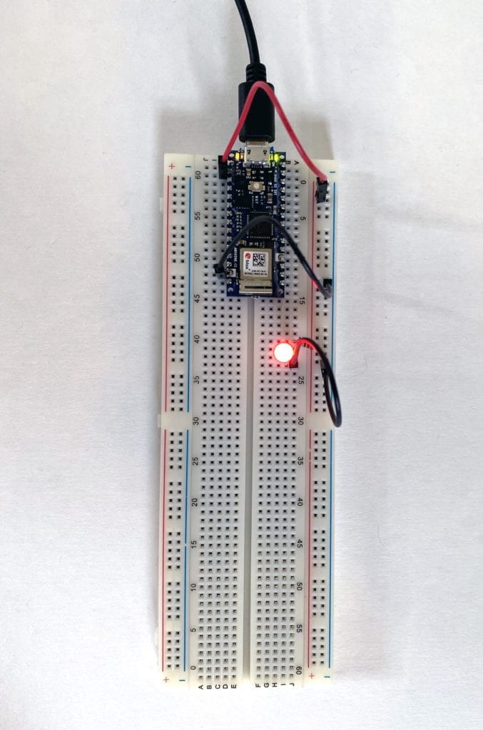
My first simple circuit was a huge success. 

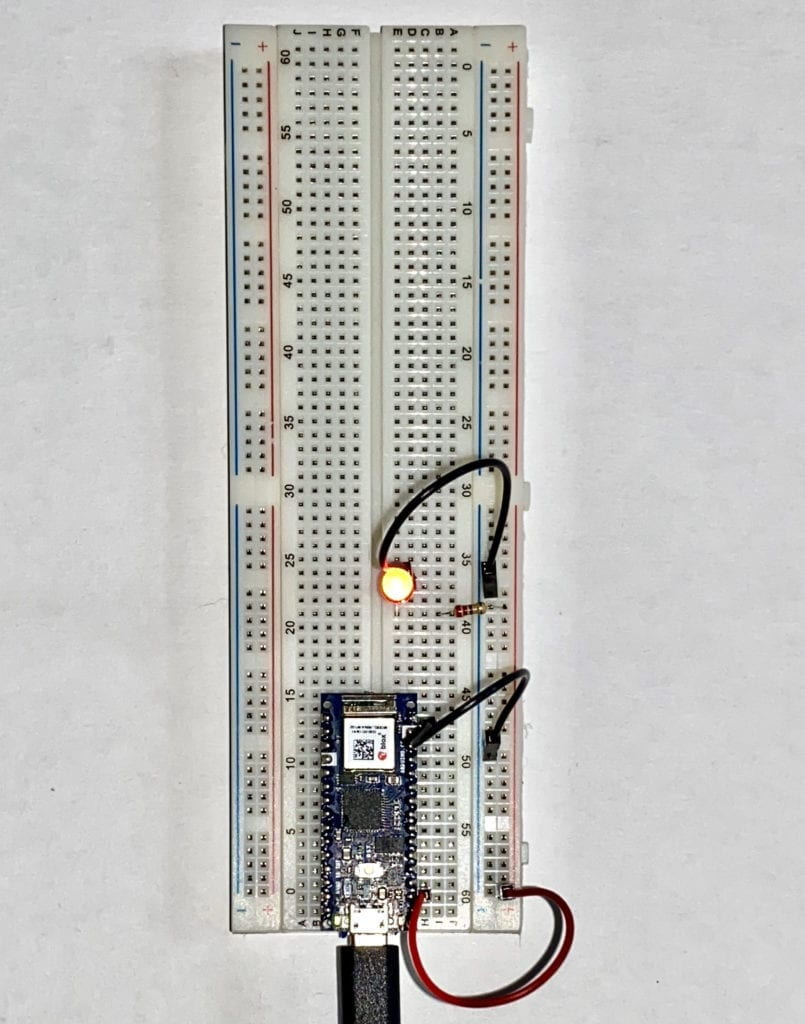
A simple circuit lighting up one LED.

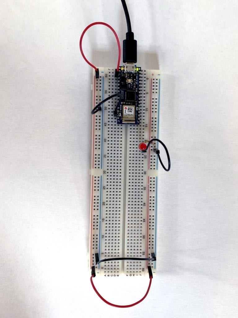
I soon ran into a problem with my second circuit. I attempted to move the LED to the other side of the Breadboard. I thought if I connected jumper wires at the bottom from the left side to the right, it would work correctly. It didn’t.

A failed circuit with the LED not lit up.

I started to experiment by removing the lower jumper cables and plugging the power and ground to the same side as the LED. Success! I now knew the Breadboard worked, and I was doing something wrong. 

A simple circuit lighting up one LED.

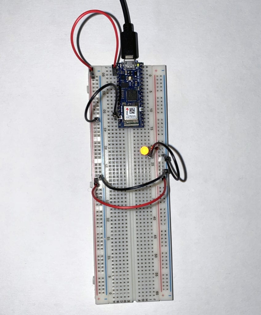
After looking at the Breadboard a little longer, I noticed a larger gap at hole 30 on both the left and right sides. I had a feeling that the + and – columns were not connected all the way. To test this, I moved the power and ground back to the left side and used jumper cables at hole 29, connecting the sides. Success again!

A simple circuit lighting up one LED.

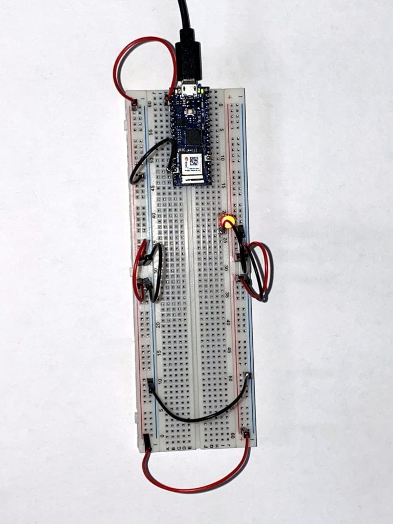
Armed with this new insight, I tried to connect the Breadboard entirely around. Success! 

A simple circuit lighting up one LED.

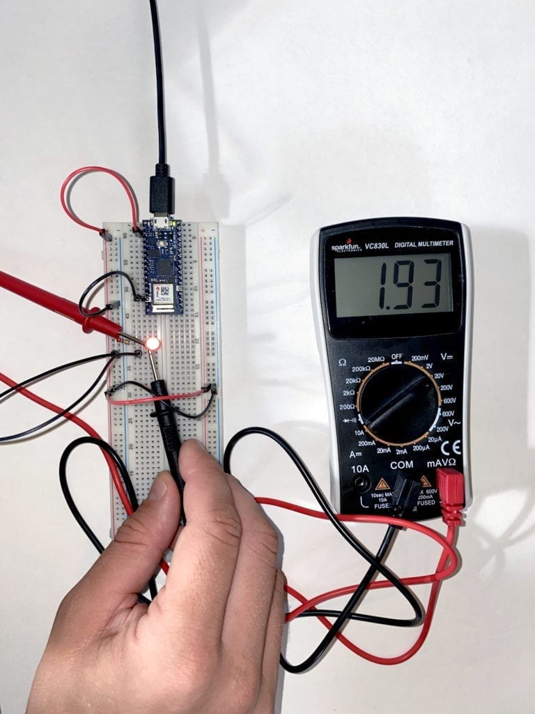
Feeling more confident, I moved on to the next section of the Lab that had to do with measuring currents. 

An image of a multimeter measuring the current running to and LED on a breadboard.

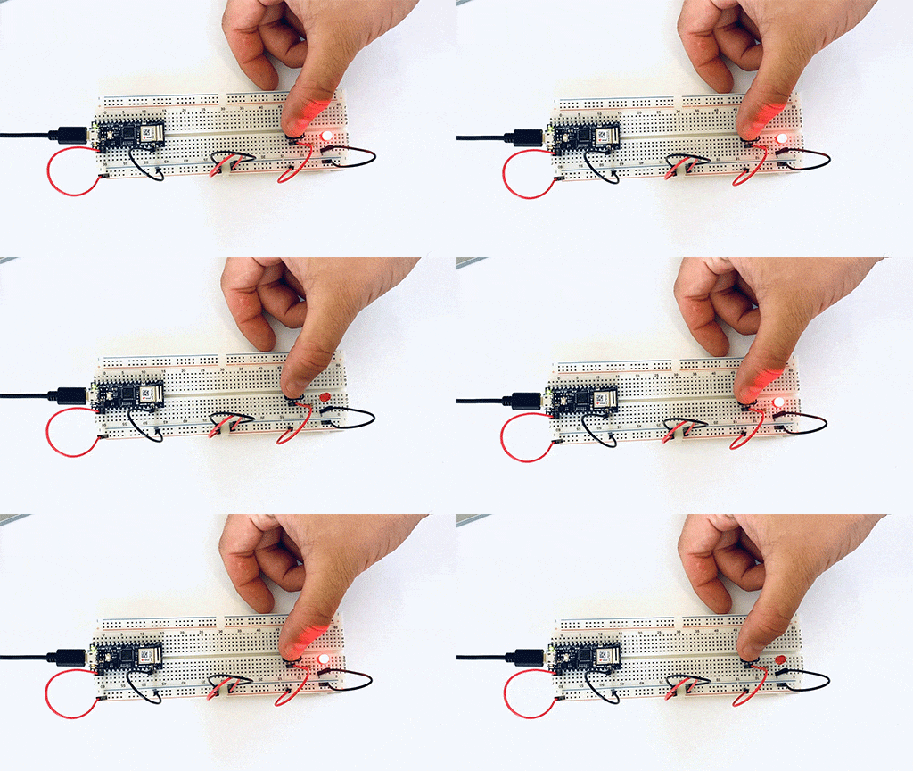
Then to switches and adding components in a series to see how the power would or would not be diminished. 

A gif of a breadboard wired with one switch and one LED.

As I continued to add components in a series, I noticed a voltage a luminance drop throughout the circuit. 

A breadboard wired with a switch and two LEDs in a series.However, when I place the LEDs in parallel, I didn’t see the drop in power or luminance. 
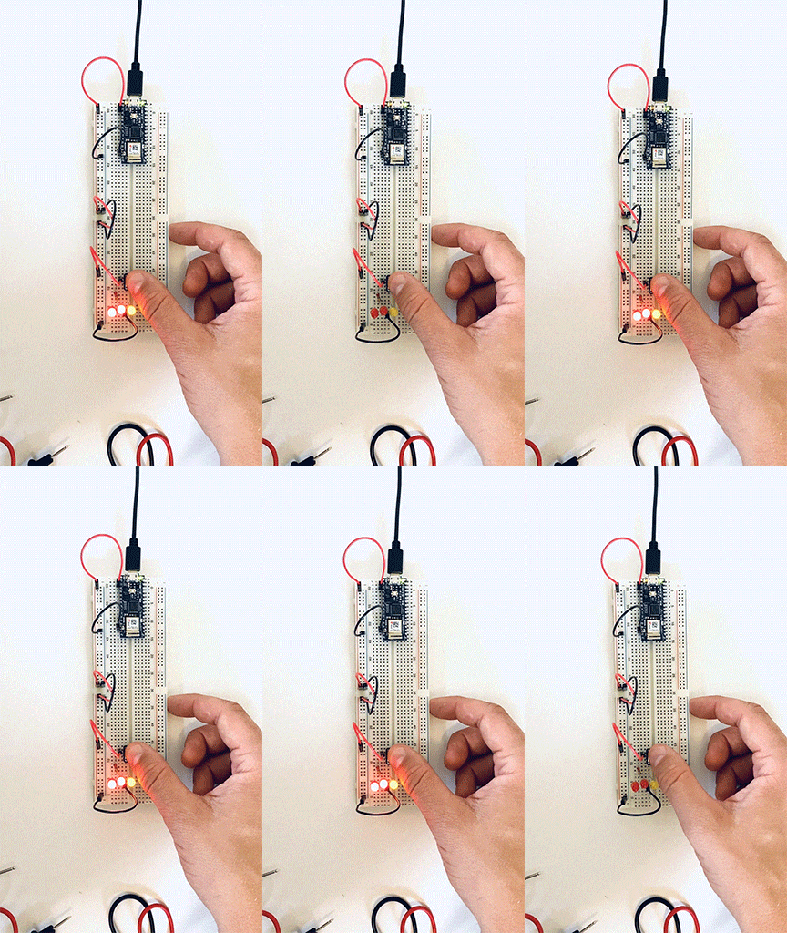
A gif of a breadboard with a switch and three LEDs wired parallel.

Next, I moved on to measuring variable voltage by using a potentiometer. There was a constant power reading between the two side points, but when I measured between a side point and the middle point, there was a change depending on how much I turned the wiper.

A gif of a breadboard wired to a potentiometer and a LED.

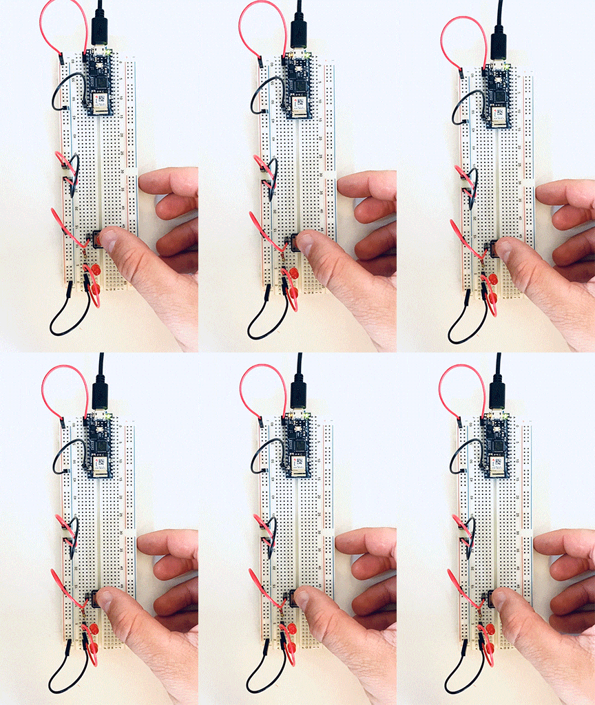
I then moved on to working with switches first in parallel than in a series. This first switch, I had to wire three times before I got the circuit correct. 

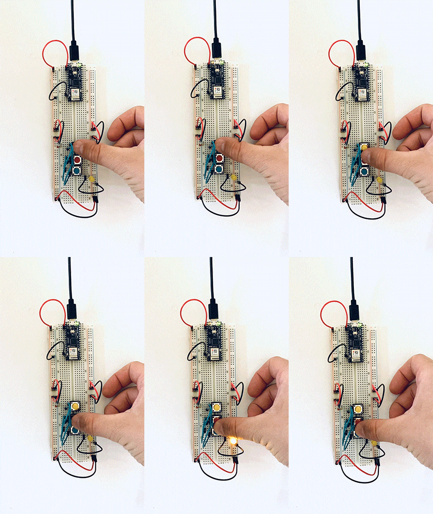
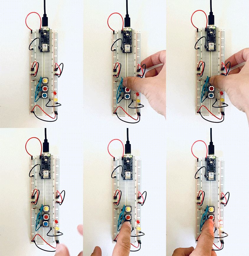
A gif of breadboard with three buttons and two LEDs. The switches are wired in parallel.

Another example of three switches in parallel, but this time, I added a second LED. 

A gif of breadboard with three buttons and two LEDs. The switches are wired in parallel.

Three switches in a series. The user needs to activate all three switches to complete the circuit. 

A gif of a breadboard wired with three buttons in a series with one LEDHere I placed one independent switch and two in a series on the same circuit. 
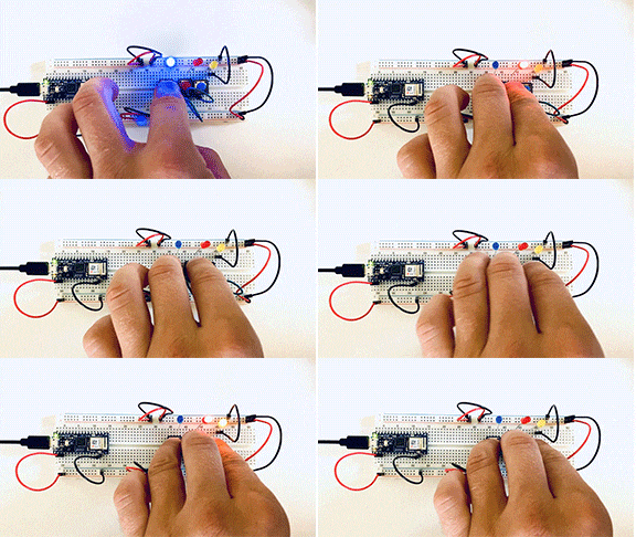
A gif of a breadboard wired with three buttons and three LED's, two buttons are in a series one is independent.

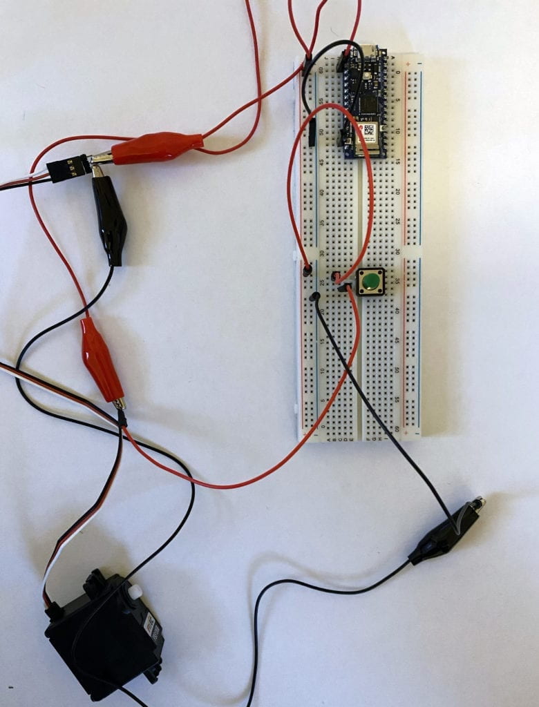
My attempt to add a motor failed. I don’t fully grasp the signal wire and believe that it needs to be coded into the Arduino. I spoke to some of my classmates, and they confirmed this.

I’m looking forward to investigating this more to get it up and running. 

Failed attempt to wire motor into a breadboard with a switch.

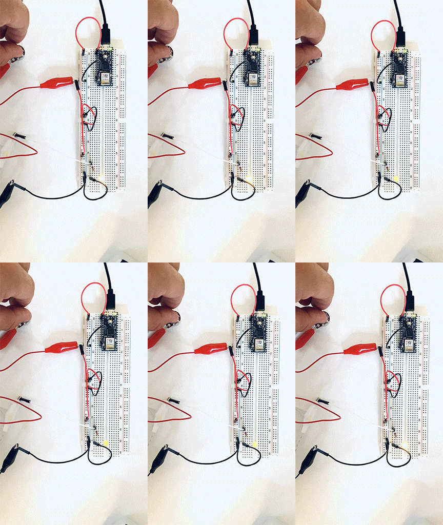
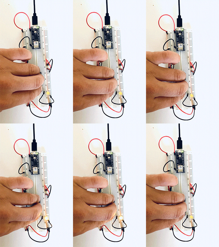
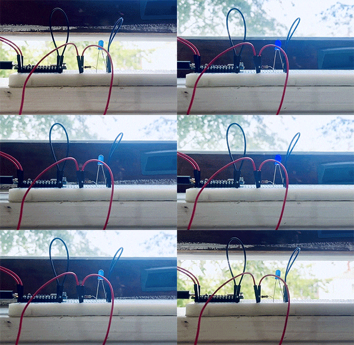
To wrap up the labs, I made a custom switch – The Window Switch; when the window is closed, the LED lights up. 

A gif of a breadboard and an LED wired to a window.