INTERACTION LAB RECITATION 1
Recitation 1:Building a circuit
Our components:
Breadboard: A construction base for prototyping of electronics. It is easy to use for creating temporary prototypes and experimenting with circuit design.
Voltage regulator: A system designed to automatically maintain a constant voltage. It is included in the circuit to avoid components damage.
Buzzer/Speaker: An audio signaling device, releases sounds.
Switch/Pushing button: Disconnect or connect the conducting path in an electrical circuit, interrupting the electric current.
Resistor: A passive two-terminal electrical component that implements electrical resistance as a circuit element. In today’s circuits, resistors are used to reduce current flow and divide voltages so that other components such as the LED don’t go overload.
Variable resistor: Adjustable resistor. Its function is the same as the resistor, except that it can alter the current flowing through.
LED: Light-emitting diode. A semiconductor light source that emits light when current flows through it. The current can only flow in one direction. Acts as a signal that the circuit is working. Attention: anode long, cathode short!
Capacitor: Store electrical energy in an electric field. It functions as a backup battery in the circuit. Or it can be used to smooth the flow of electricity.
Power: Electricity output.
Wire: Are used to bear mechanical loads or electricity and telecommunications signals.
Ground: The return path for current. The voltage here is 0v.
Multimeter: A measuring instrument that can measure multiple electrical properties.
Task 1: Build the circuits
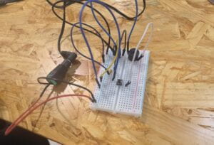
Circuit 1: Door Bell


My partner and I both took physics in high school, so we are familiar with circuit diagrams and components. The biggest problem for us was the breadboard. We studied it for a while and even tried to search the Internet for tutorials, but didn’t understand its construction. Finally, we bravely asked the learning assistant for help, and she told us the construction of the breadboard: the wide strip of vertical jacks are connected to each other, and none of the horizontal jacks are connected; there are two vertical rows of jacks on both sides of the board, and the jacks are used to provide power to the components on the board, which are connected to each other horizontally.
Thanks to the help of the Learning Assistant, we are in the phase of building the circuit. After connecting the circuit according to our understanding, the buzzer did not work. Checking on our own with no results, we asked Professor Marcela for help. The professor told us that the three ports of the regulator should be connected strictly according to the schematic.

In addition, the switch would be better placed at the groove in the center of the breadboard used to isolate the top and bottom parts of the jack. As Rudy emphasized in the previous class, the legs of the switch are connected two by two and the two sets are independent. (Actually, the reference schematics are very clear)

After some adjustments, our buzzer finally made a sound. Even though it was a simple circuit, it was the first little task we accomplished in our recitation class!
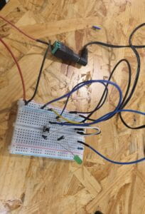
Circuit 2: Lamp


With the success of the doorbell, we only need to make slight modifications to the original circuit and replace a few components to complete the circuit of the lamp.
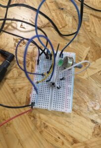
Circuit 3: Dimmable Lamp


It should be noted that the LED has a unidirectional conductivity, so pay attention to the positive and negative polarity when accessing the circuit. The interface of the variable resistor should also be in accordance with the diagram.


So looking carefully at the schematic is really important!
Task 2: Switch the switches
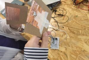
I learned how to solder for the first time. The experience was interesting and I was a little afraid of burning myself at the beginning, but my partner said I did a good job. We each soldered long wires to an arcade button made of cardboard and metal pieces, and the two came together to make a switch.

We managed to replace the push button switch with one we made ourselves.
Question 1:
After reading The Art of Interactive Design, in what way do you think that the circuits you built today include interactivity? Please explain your answer.
Interactivity is defined in a broader sense as “inputs, process, and outputs”. The circuits I built today do contain such processes, for example adjusting variable resistors to emit different brightnesses of LED is an input and output. The author also mentioned “degree of activity”. The circuit we built is obviously only a low degree of interactivity. But it does include interactivity – at least we were very happy when we were able to interact with it.
Question 2:
How can Interaction Design and Physical Computing be used to create Interactive Art?
I believe that interaction design and physical computing are two indispensable elements in creating interactive art. We need creative and meaningful design, and physical computing technology sufficient to make it happen.
In Zack Lieberman’s video, he introduced the project Eyewriter. The project is to help paralyzed people draw and write again by capturing their eye movements. They used physical computing to create eye-tracking software and hardware, while graffiti drawn by paralyzed artists using the device was projected onto hospital buildings. Without the projection part, the project would have been a mere technical tool. But projecting these works, created by turning the eyeballs, onto the hospital building presents a sense of interaction design. It not only gives the viewer an interactive shock but also gives the artist a kind of rebirth.