ItR Mini Project 2: Escaping Robot
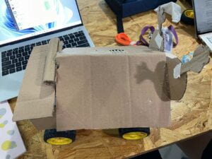
Final Result
Building Procedure
The building of this robot is based on the last one. If you are interested in the main body-building procedure, you can see this post for greater details.
The majority of change that we’ve made was the addition of the Light Dependent Resistors. At the very beginning, I discussed the amount and the position of the Light Dependent Resistors with my partner. We’ve discussed 3 plans:
1. Only 2 LDRs at the front of the robot.
2. 4 LDRs. 2 at the front, 2 at the back.
3. 4 LDRs. 1 at each side of the robot.
After a short discussion, we’ve chosen the 3rd plan. The 1st & 2nd plan has too many restrictions. The front LDRs cannot work properly if the robot has crushed onto the wall. In addition, the LDRs cannot detect the light from their side if all the sensors are toward the front and the back.
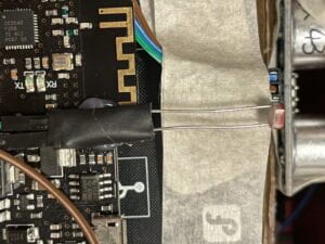
Then we started to build the circuits. Firstly, we need to put the sensors properly. The positions of each LDR are far away from each other. In this case, we cannot just plug them on the breadboard. So we soldered the LDRs with the jump cables and wrap them with tape in order to ensure their structural strength.

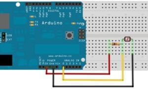
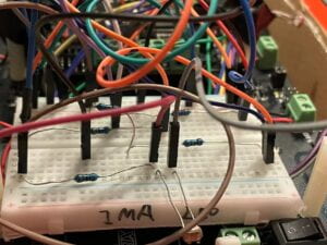
Then we connect the circuits following the instructions by 4.

To test if all the sensors are working properly, I use the following code to test the output index of each LDRs.
void setup() { // initialize serial communication at 9600 bits per second: Serial.begin(9600);}void loop() { int sensorValue = analogRead(A0); Serial.print(sensorValue); // print out the value you read: Serial.println(); delay(1); //adding up to 10ms in the loop is harmless to our moving robot}
int sensorValueL = analogRead(A0); //left default 600 int sensorValueR = analogRead(A1); //right default 670 int sensorValueF = analogRead(A3); //front d 500 int sensorValueB = analogRead(A4); //back d 640 int realL = map(sensorValueL, 400, 800, 255, 0); int realR = map(sensorValueR, 420, 820, 255, 0); int realF = map(sensorValueF, 0, 500, 0, 500); int realB = map(sensorValueB, 0, 640, 0, 500); if(realB > realF){ carBack(realL, realR); delay(100); }else{ if(realL > realR && realL - realR > 10){ carTurnLeft(realL, realR); delay(100); }else if(realR > realL && realR - realL > 10){ carTurnRight(realL, realR); delay(100); }else{ carAdvance(200, 200); delay(100); } }

// Global variable declarationint speedPin_M1 = 5; //M1 Speed Controlint speedPin_M2 = 6; //M2 Speed Controlint directionPin_M1 = 4; //M1 Direction Controlint directionPin_M2 = 7; //M1 Direction Control// the setup routine runs once when you press reset:void setup() { // initialize the outputs that the motor drivers need int i; for (i = 4; i <= 7; i++) pinMode(i, OUTPUT); // initialize serial communication at 9600 bits per second: Serial.begin(9600);}// the loop routine runs over and over again forever:void loop() { // read all the sensors here int sensorValueL = analogRead(A0); //left default 600 int sensorValueR = analogRead(A1); //right default 670 int sensorValueF = analogRead(A3); //front d 500 int sensorValueB = analogRead(A4); //back d 640 int realL = map(sensorValueL, 400, 800, 255, 0); int realR = map(sensorValueR, 420, 820, 255, 0); int realF = map(sensorValueF, 0, 500, 0, 500); int realB = map(sensorValueB, 0, 640, 0, 500); // if (-100 <= realB - realF <= 100) { // carStop(); // }else if(realB > realF){ carBack(realL, realR); delay(100); }else{ if(realL > realR && realL - realR > 10){ carTurnLeft(realL, realR); delay(100); }else if(realR > realL && realR - realL > 10){ carTurnRight(realL, realR); delay(100); }else{ carAdvance(200, 200); delay(100); } } // decide how to control the actions here // if ( sensorValue0 <= 500 ) { // int speedM1 = map(sensorValue0, 30, 500, 255, 100); // Serial.print(" is the sensor0 value, I calculate speed "); // Serial.print(speedM1); // carAdvance(speedM1, speedM1); // //delay(500); //do not use long delays within loop, unless necessary // } else { // if ( sensorValue0 <= 500 ) { // int speedM1 = map(sensorValue0, 30, 500, 255, 100); // Serial.print(" is the sensor0 value, I calculate speed "); // Serial.print(speedM1); // carAdvance(speedM1, speedM1); // carStop(); // } delay(1); //adding up to 10ms in the loop is harmless to our moving robot}// Auxiliary functions to move the robotvoid carStop(){ // Motor Stop digitalWrite(speedPin_M2,0); digitalWrite(directionPin_M1,LOW); digitalWrite(speedPin_M1,0); digitalWrite(directionPin_M2,LOW);}void carTurnLeft(int leftSpeed,int rightSpeed){ //Move backward analogWrite (speedPin_M2,leftSpeed); //PWM Speed Control digitalWrite(directionPin_M1,HIGH); analogWrite (speedPin_M1,rightSpeed); digitalWrite(directionPin_M2,HIGH);}void carTurnRight(int leftSpeed,int rightSpeed){ //Move forward analogWrite (speedPin_M2,leftSpeed); digitalWrite(directionPin_M1,LOW); analogWrite (speedPin_M1,rightSpeed); digitalWrite(directionPin_M2,LOW);}void carBack(int leftSpeed,int rightSpeed){ //Turn Left analogWrite (speedPin_M2,leftSpeed); digitalWrite(directionPin_M1,LOW); analogWrite (speedPin_M1,rightSpeed); digitalWrite(directionPin_M2,HIGH);}void carAdvance(int leftSpeed,int rightSpeed){ //Turn Right analogWrite (speedPin_M2,leftSpeed); digitalWrite(directionPin_M1,HIGH); analogWrite (speedPin_M1,rightSpeed); digitalWrite(directionPin_M2,LOW);}

