IxLab Recitation 2: Arduino Basics
Building Process
Circuit 1
Circuit 1 is a circuit that can let the LED fade. No problems were encountered during building circuit 1.
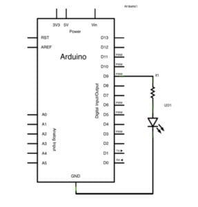
My Built Circuit 1
Circuit 2
Circuit 2 is a circuit that can let the buzzer play music. When dealing with the code, we can let the buzzer play notes through different functions.
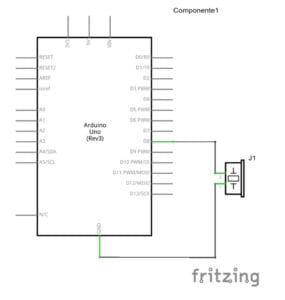
My Built Circuit 2
Circuit 3
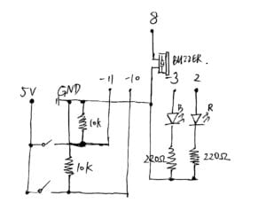
Circuit 3 is a competition game, fuse the circuit with the serial monitor. The information will be displayed on the screen while the user needs to interact with the buttons in the circuit. When building the circuit, my partner and I both built half of the circuit on one breadboard. The problem that we encountered was that the jumping cables made our circuit hard to read which lead to the fact that we can hardly know which pin should we plug in at the very end of the building process.
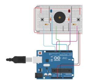
My Own Schematic
My Built Circuit 3
Questions
Question 1: Propose another kind of creative button you could use in Circuit 3 to make the game more interactive. Read and use some material from the Physical Computing, Introduction Chapter (p. xvii – p. xxix) to explain why this button would make this game more interactive.
We can add microphones to make the game more interactive. The players need to shout out loud after finishing the pressing procedure since the brightness of the LED is determined by the volume received by the microphone. The microphones let the players have a more interactive degree with the circuit. According to the book “Physical Computing”, the interaction is divided into 3 parts: input, process, and output. The players can give the computer another input through the microphone, The computer needs to process more data since the microphone data is input. In this case, the addition of the new microphone gives the players more options to interact with the computer.
Question 2: Why did we use a 10 kOhm resistor with each push button? (Psssst… Go back to your slides for this answer)
By observing the circuit, we can see that one side of the push button is the 5v power source while the other side is the GND and the DigitalPin. If without the resistor, the 5v will directly connect with the GND when the button was pressed. In this case, the DigitalPins will be short-circuited by the GND and have no input signal. In addition, when the button is not pressed, the DigitalPins are directly connected to the GND if there’s no resistor between them. In this case, a short circuit will happen.
Question 3: In the book Getting Started with Arduino there is a clear description about the “Arduino Way” in chapter 2. Find a project that you find interesting that can be used as an example for these kind of projects. Cite it in adequate manner, include a picture, and explain the reasons that you chose it.
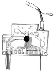
The project that I choose is the keyboard hacks. The “input” is one of the essential elements of interaction. The keyboard is the most common device that we input information. We can change the way we use the keyboard by shifting pressing the key button to other ways. Punching the sensor(force sensor) or using the microphone to trigger the input action. This means that we can fuse the interaction with the computer input. Don’t you think it’s cool? As a student who is keen on science and technology, I think it’s so cool. It’s perfectly consistent with my imagination of future life. Scientific along with the interesting.
