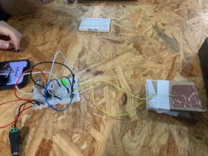
today, in the recitation class, we are asked to make four circuits, each one is an improved version of the last one. we are wished to learn the knowledge of circuits as well as the knowledge of switches through this progress of making. we borrow ideas from what we have learned on Thursday. first, we are told to stay safe during the whole process and how to prevent the circuits from burning. we also learn how to weld as well. our team first asked the professor about the theory of the circuit board and then try to connect our circuit according to the circuit picture but we failed the first time because we put the buzzer wrongly. then the switch doesn’t work. it turned out we have bypassed the switch. and then everything worked. although the whole thing didn’t go completely as planned, we managed to do what we are told to do. what we have learned is that we should always double-check whether some devices are being bypassed when we are making a circuit. also, we should prevent ourselves from getting hurt when welding. the followings are answers to the questions. all pictures and videos will be attached at the end of
the first step of the first task. the first circuit can make the buzzer buzz when we press the switch. we first connect a wire to the positive side and then connect it to the buzzer’s positive side. then we take another wire and connect it to the buzzer’s negative side and one side of the switch. we then connect the other side of the switch with the negative side of the power with another wire. but the first time we connect this circuit without the switch, the buzzer doesn’t buzz. so we asked the assistant what was going on and she explained that we have bypassed the buzzer and we should turn the buzzer 90 degrees around. we tried and it worked! and then we added the switch this time we are extra careful about not bypassing any device. and this time, the switch worked.
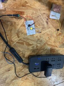
the second step of the first task. the second circuit can make light lights up and buzzer buzz at the same time with the switch. we take another wire and connect it between the resistant and the positive side of the buzzer. we take another wire and connect it between the resistant and the positive side of the LED. a third wire is used to connect the negative side of the LED with the switch. there are moments when we connect the wire to the wrong row but we corrected it in time and we succeed the first time.
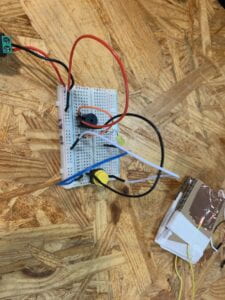
the third step of the first task. the third circuit can make one light lights up all the time and the rest is like the second circuit. we connect the light and the resistance as well as the POT and connect them to the positive and negative sides of the power. we first didn’t know how the POT worked so we asked one professor about it and he explained it patiently. then we found we the light won’t light up and found out we have again connected the wire to the wrong row. after we corrected this, the circuit worked.
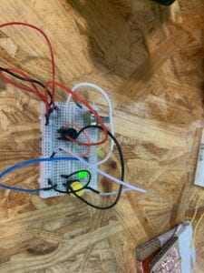
when I’m working with my partner, we will study the pictures of the circuits together and the boys will do most of the job of installing them. they will also explain to me when I don’t understand because they took physics in high school and I didn’t.
in step two. we first cut two pieces of rubber out of the wire at each end. next, we tried out one piece of copper and stick it to one end of the cardboard. the next step is to stick the two boards together and fix our wire to the copper-free end of the cardboard, making the bare wire touch the copper. then we are taught how to use the electrode holder and we use the electrode holder and fix the bare wire to the copper. I learned how to use an electrode holder and how every kind of metal can pass electricity. the only difficulty we encounter is that my partner’s hand was cut open by copper. the professor tends to him immediately.
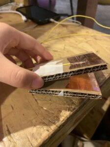
in step three, we connected the copper switch with the circuit and use the whole device to make the Morse code of SOS. we insert one end of the bare wire into the place where the old switch was on and the other side the same. I worked well with my partners.
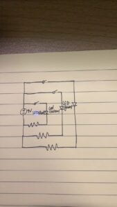
question one: the resistance of the LED is quite small so the electricity will be large and the LED has a possibility of being burned. so we need to make the resistance bigger by adding R1. question two’s answer is attached below
question three: I think today’s circuit is interactive because the circuit can first listen to me (feeling me pressing the switch), think (letting the electricity go through the whole circuit), and speak (making the light lights up or the buzzer buzzes). and I have also listened (seen the light lights up and the buzzer buzzes), thought (thought about what to do next), and spoken (pressed the switch). but I think the degree of interaction is pretty low. because the device is not speaking well enough. it just lights up and buzzes and does nothing else, it’s neither interesting nor beautiful.
question four: I think to create interactive art, we need two steps, firstly, the artist creates an artwork. next, the viewers interact with the art. so interaction design and physical computing can be used in those two steps. firstly, we can use physical computing to make an interaction design. then we use this interaction design to interact with people and create interactive artworks. for instance, in Lieberman’s project, he first use physical computing to build the eye tracking device which is also interactive. then people can use this eye tracking device to create artwork. references: Art of Interactive Design,