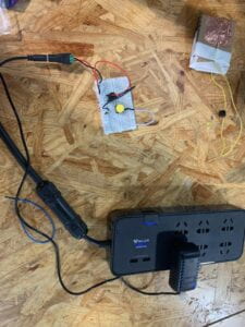
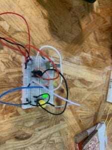
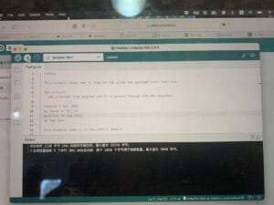
1. the first device I made can make the light lights up and dims down slowly in sequence. our assignment is to make a circuit that can make the light fade. we are hoping to learn how to build a circuit according to the circuit diagram. and how to use the existing code in Arduino. I did it pretty easily and without failure. I first understood how the circuit diagram worked and then build my circuit accordingly. I learned from this activity that whenever we are going to build a circuit, we should first draw a circuit diagram and that will make the whole process a lot easier. here is the code and the video of my circuit working.
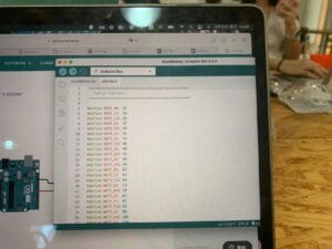
2. the second device I build is a device that will play a piece of music when the circuit is on. this circuit is also meant to let us know what it is like to read circuit diagrams and how to use the existing code. during this project, I failed the first time because I didn’t choose the file so the code can not be uploaded to the Arduino. so the hummer will only hum once and stopped. then I found out there was a problem there and corrected it. so the hummer will hum a piece of music for me. although the plan didn’t go as planned, I still learned something. it has come to my notice that I should always check whether the code has been uploaded or not before making the whole circuit work. the following is the code and video about my circuiting working.
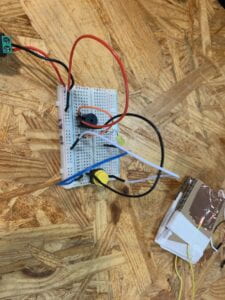
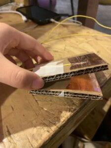
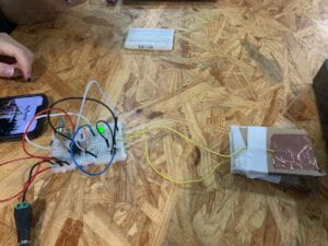
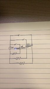
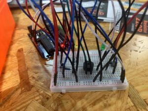
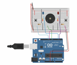
3. the third circuit I built is a bit complicated. it is a game that can be played by two people. the person who first presses the button on his or her side ten times will have his or her side of the light lights up and the hummer hums. we are hoping to learn how to connect complex circuits according to the circuit diagram. and how to upload code from Autodesk. although the circuit diagram is difficult to read, I still manage to get it right the first time. the thing I learned from this circuit is that we should draw the circuit diagram clearly so that we could able to connect the whole circuit correctly. I come to that conclusion because without a clear circuit diagram, I could never come up with the circuit correctly. the following is the picture of my circuit and how it works as well as the circuit diagram.
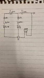
4. the first question: I think the creative button that can be used in the third circuit is that the music played by the buzzer will be determined by how much time the winner uses to push ten times of the button. the reason why it is more interactive is that the whole model will no longer be digital but analog. because the judgment that is used is no longer yes or no about who presses the button faster but about exactly how much time they use to push the button. in that way, the output of this device is more interactive so it is more interactive.
5. the second question: the reason for having a 10k resistance for the push button is that we need to have a resistance big enough that if the button is off, the pressure will be small enough to count as 0 for the computer. also, it has to be big enough so that the button can be protected from the big current.
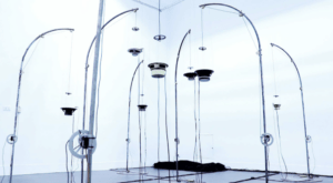
6. the project I found is a project in which the ceiling will move according to how people move underneath the ceiling. I choose it because it can show how an Arduino is not simply creating roads from A to B but lost in finding a way to C. there’s no set way for the ceiling to move. instead, it will move according to how people underneath move. that is why I find it interesting.

7. references cited
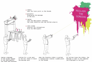
Forman View all posts by Eric Forman, Eric, et al. “SMS Slingshot by VR/Urban.” HelloCircuits!, 13 Sept. 2015, https://hellocircuits.com/2012/04/29/sms-slingshot-by-vrurban/#more-9744.
