Author Archives: William Mlekush

Project Week 7: Self Portrait

Concept

I am not made up of me. I am made up of the intersection of every entity I have encountered. A self-portrait, then, should not look like me, but should be the amalgamation of all of the faces of all those who have influenced me. I created a self portrait using faces of several of those people who have been most influential in the development of my identity. 

The code and self-portrait can be accessed here.

Process

I found available head shots of the people online, edited them in Photoshop to all be the same size, and divided them into quarters. Each set of quarters is then cycled through in its appropriate location on-screen.

Responding to Igoe

Igoe’s point in Making Interactive Art: Set the Stage, then Shut Up and Listen brought me to reconsider a persistent comment made by our professor about my midterm: it should have an on-off switch. I disagreed, pointing out that pressing the reset button on the arduino or simply removing a battery would reset the machine. Now, however, I realize that both of those things require the user to interact with the background, to move outside of the immediate interaction using context they may not have. Without a clear place to turn the machine on and off or reset it, one person would solve the lock, and it might never be used again.  This is a small moment, but an important idea. Designers often fall prey to the trap of creating a design which is too clever for its own good; so seamless that it not only goes unnoticed, but completely unused. Avoiding this trap means empathizing as much as possible through creating user personas and running usability tests as is feasible. While Igoe does not go into these practices specifically, he proceeds to analyze common physical computing projects based upon how clear and stable the interaction is, rather than how clever the technology or mechanism behind it is.

In this analysis Igoe also offers the point that interactive art students should not dissuade themselves from executing a project because it has been done before, and should focus instead on expanding upon unique themes. I appreciated this point and how it is applied in the design of this course. While the frustration of the freedom to do whatever I can with what we have learned so far is palpable at the beginning of each build, by the end it is satisfying to be able to work on a concept I chose rather than one imposed on me. I do, however, have reservations about conceptual art due the unintended consequences. Igoe covers this well in the first text, with how ideal ignorant users will interact unexpectedly. It’s important, then, to strike a balance between behavior constraints and conceptual hindrance.

Midterm Build: Audio Lockpick

Concept
This build started with a contemplation of what it means to design for the brave. A quick brainstorm, pictured below, brought about four concepts. Each concept requires the user to perform an action despite the use of positive punishments when that action is taken. Positive punishment in psychological jargon just means some stimulus is presented in order to inhibit the repetition or persistence of a behavior. The Moody Cat would have the user pet the right spot on a screaming and angrily vibrating cloth blob. Used would have the user actually kill the robot, a commentary on how bravery and persistence can have unintended consequences. Danger Chamber would test the users dedication to stopping an annoying or terrifying noise, giving them the choice to be brave and endure the noise or be brave and risk slicing their hands open. Audio Lock Picking, the design I developed further, would provide a challenge similar to physical lock picking in order to stop an annoying or terrifying sound. After a consultation with our TA, I decided to pursue Audio Lock Picking due to time and skill constraints; it was the design I could most clearly understand in terms of both back end and front end work.

The origin of the idea came from a work break I had with some friends in the Engineering & Design Studio. After some coffee, we went over to a little table filled with physical puzzles and began trying to solve them. Among these puzzles were several different types of lock. After a few minutes of playing with them, I realized my week three build was similar in that the user had to find the right combination. During the brainstorm, I tried to extend the concept from the simple mental note I had, and the result was Audio Lock Picking.

Circuit
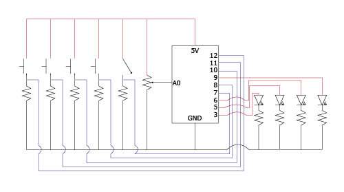
After the brainstorm, I started by prototyping the circuit. I knew I would need a potentiometer, buzzer, motor, and several LEDs, all in parallel. This was the result:

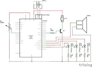
Audio Lock Picking circuit schematic

Behavior

Edit: I made the mistake of not filming the fully functioning build and letting it sit for an entire day. I have encountered a problem, discussed later, where the driving shaft keeps unscrewing itself from the DC motor. As a result, I have two videos to showcase the build’s functionality.

When the Arduino turns on, two things happen simultaneously. The motor begins to spin and the speaker begins to play a tone. The spinning of the motor drives a simple slider-crank mechanism which is attached to the motor by an M1 bolt threaded into the center hole and an M1 nut.

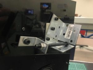
The slider-crank is constructed out of acrylic and a series of nuts and bolts. The driving shaft is an M1 bolt. The crank is a small acrylic square (about 3.5cm x 3.5cm). The hinge pin is an M4 bolt connected to an l-bracket. The rod is the shaft of a long M4 bolt, and the slider is its head. Nuts and washers are used to manipulate the friction forces so that the rod turns independently of the crank and the crank turns with the driving shaft.

As the motor turns, the rotary motion is converted into linear motion and the head of the long M4 bolt strikes the two fixed l-brackets repeatedly, creating an annoying noise. The angled placement of the L brackets was not ideal, but necessitated by the way their holes overlap.

At the same time, the speaker begins to play a tone. The tone is based upon the value of the potentiometer read by the Arduino, which has been mapped in the code so that “continuous” tones between 120 and 1500 Hz are played.
As the user turns the potentiometer an LED will turn on based upon the range of values from the potentiometer that the Arduino is checking for. If the user moves to quickly, they will see a blink or nothing, as the potentiometer values might jump the key range. As in physical lock picking, where pins rarely set easily, the tone does not immediately turn the LED on permanently. The user must hold the tone within the range for two seconds in order for the LED “pin” to “set” or turn on permanently. When the first LED is on, a brief arpeggio plays, and the key range changes. When this range is set, the second LED turns on, another arpeggio plays, and the key range changes. When this range is set, the third LED turns on, and a final arpeggio will play. Upon the completion of this arpeggio, the speaker plays an inaudible tone, and the motor stops. The user has successfully picked the lock.

Discussion
This build was not incredibly challenging in terms of hardware, but the coding was a stretch. I spent a long time messing around with for loops and nested if statements before I asked our wonderful TA for help. He helped me work through the proper logic. However, I did drop a few functions. Initially, I wanted to have the speed of the motor decrease with each successful LED light-up in order to more clearly signify the connection between turning on the LEDs and stopping the annoying noise. I also wanted to have the tone ranges change with each activation. Initial experimentation, though, resulted in several unexpected problems that I could not resolve in a timely fashion and that would not be significant improvements to the user experience. While I accomplished the most important functions for the purposes of the assignment, I would like to figure these features out when I have a spare block of time.
I did have a few hardware problems. I snapped an LED and a motor cable (PICTURES) and had to replace them.

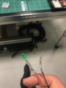
An LED snapped when I twisted the legs to put them into the panel.

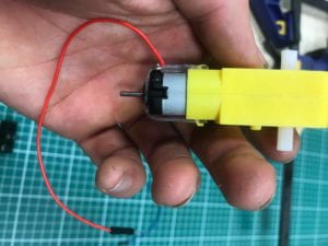
I cut the zip-tie holding the wires to the motor, and the ground just fell off. (Also ft my hand after 4 hours of working with black acrylic and black steel.)


I also had difficulties with the driving shaft of the slider crank unwinding itself and falling off. I solved this by adjusting the tension of the nuts to lock the driving shaft to the motor and the crank, so they behave as a single unit, leaving only the rod to rotate freely.

There was also the problem of not designing the physical structure as well as I would have liked. If I were to improve the build, I would move the Arduino and breadboard to the center of the lower third of the panel so that I could have equal bracing on either side rather than the current staggered bracing, which makes the side with the smaller l-bracket more susceptible to damage. I also should have planned out my layout better and figured out some way of marking the acrylic in a temporary way. This would have helped prevent the several misplaced holes in the panel, and would have allowed me to put the LEDs in a straight horizontal or vertical line. I also would have experimented with whether a vertical or horizontal crank-slider mechanism would have been better. A vertical crank-slider would have made more efficient use of space and materials, requiring only a single l-bracket whose footprint on the panel could have overlapped with the crank-slider. However, I am wondering if the motor would be able to lift and drop the rod repeatedly, without it falling off, without the support provided on the Slider by the current two-l-bracket system. Finally, if I were to create this as a more permanent build, I would have used lock nuts and maybe some glue on the LEDs.

Edit: The crank slider keeps unscrewing itself from the motor. The direct cause is that the drive shaft stops while the motor spins, resulting in a reverse threading of the drive shaft. There are three potential contributing causes of the stopping of the drive shaft.

  1. The torque required to move the drive shaft will vary with the position of the crank it its rotation. As a result, of this, there may be a moment where the drive shaft stops, a moment which may be exacerbated by an angling of the motor due to poor placement. I lack the physics knowledge to explain this problem entirely. 
  2. Every time the rod strikes the l-bracket, it stops, causing the entire mechanism to stop briefly. Over time, this reverse-threads the drive shaft. One fix would be to adjust the length of the rod. 
  3. As the rod slides back along the horizontal l-bracket, it catches briefly on a hole designed for the l-bracket to attach to another piece. 

A specific fix for problem one would be to create a better, custom attachment for the DC motor which embeds it into the panel, rather than holding it by hanging it from a bolt and putting a zip-tie around it. This would at least eliminate any sort of angling of the mechanism. Problem two could be solved by adjusting the length of the rod. Problem three could be solved by using a continuous smooth surface for the slider to move along. A comprehensive fix, on the other hand, would be to create a drive shaft which fits around the motor instead of threading inside of it.

Code

int const LED1Pin = 12;
int const LED2Pin = 11;
int const LED3Pin = 10;

int const potPin = A0;

int const speakerPin = 9;

int const motorPin = 5;

#include "pitches.h"

//notes in feedback melody for when LEDs are activated for 2s
int LED1FeedbackMelody[] = {NOTE_A4, NOTE_CS5, NOTE_E5, NOTE_A5};
int LED2FeedbackMelody[] = {NOTE_CS5, NOTE_E5, NOTE_A5, NOTE_CS6};
int LED3FeedbackMelody[] = {NOTE_E5, NOTE_A5, NOTE_CS6, NOTE_E6};

//setting trigger variable for melody to play
bool LED1FeedbackMelodyTriggered = false;
bool LED2FeedbackMelodyTriggered = false;
bool LED3FeedbackMelodyTriggered = false;

//length of notes variables
int const noteDuration = 100;
int const pauseBetweenNotes = 130;

//note position variables
int const initialNote = 0;
int const totalNotes = 4;

//setting variables for checking that the LED has been on for 2s
bool LED1Triggered = false;
bool LED1Over2s = false;

bool LED2Triggered = false;
bool LED2Over2s = false;

bool LED3Triggered = false;
bool LED3Over2s = false;

int LED1MillisCounter = 0;
bool LED1MillisTriggered = false;

int LED2MillisCounter = 0;
bool LED2MillisTriggered = false;

int LED3MillisCounter = 0;
bool LED3MillisTriggered = false;

//set motor speed variables

int const motorFullSpeed = 255;
int const motorOff = 0;

void setup() {

  pinMode(12, OUTPUT);
  pinMode(11, OUTPUT);
  pinMode(10, OUTPUT);

}

void loop() {

  //code to make speaker play accoding to pot input
  //read potentiometer and map pitch to it
  int potValue = analogRead(potPin);
  int pitch = map(potValue, 0, 1023, 120, 1500);

  //code to light up first LED when certain pitch plays
  //set variables for LED states
  bool LED1State = digitalRead(LED1Pin);

  //make first LED triggered if between pitches of 550 and 650
  if (pitch >= 550 && pitch <= 650) { LED1Triggered = true; } //if LED1 is triggered, then turn on LED1 if (LED1Triggered) { digitalWrite(LED1Pin, HIGH); //these next lines capture the exact moment the LED turns on if (!LED1MillisTriggered) { LED1MillisCounter = millis(); LED1MillisTriggered = true; } else digitalWrite(LED1Pin, LOW); //if the millis counter = //the inital moment it was turned on is greater than 2000 //then it has been turned on over 2s if (millis() - LED1MillisCounter > 2000) {
      LED1Over2s = true;
    }
    //if LED1 is outside the range
    //and it has been more then two seconds
    //then we want the rest of the things to trigger
    //otherwise, turn it all off, reset the counter
    if (pitch > 650 || pitch < 550) { if (millis() - LED1MillisCounter > 2000) {
        LED1Over2s = true;
      } else {
        LED1Triggered = false;
        LED1MillisTriggered = false;
      }
    }
    //if LED has been turn on over two seconds, then turn on the LED "permanently"
    if (LED1Over2s) {
      digitalWrite(LED1Pin, HIGH);

      // and play notes of feedback melody:
      if (!LED1FeedbackMelodyTriggered) {
        for (int thisNote = initialNote; thisNote < totalNotes; thisNote++) { tone(speakerPin, LED1FeedbackMelody[thisNote], noteDuration); delay(pauseBetweenNotes); noTone(speakerPin); LED1FeedbackMelodyTriggered = true; } } } } //LED 2 bool LED2State = digitalRead(LED2Pin); if (pitch >= 1150 && pitch <= 1250 && LED1Triggered == true) { LED2Triggered = true; } if (LED2Triggered) { digitalWrite(LED2Pin, HIGH); //these next lines capture the exact moment the LED turns on if (!LED2MillisTriggered) { LED2MillisCounter = millis(); LED2MillisTriggered = true; } else digitalWrite(LED2Pin, LOW); //if the millis counter = //the inital moment it was turned on is greater than 2000, //then it has been turned on over 2s if (millis() - LED2MillisCounter > 2000) {
      LED2Over2s = true;
    }
    //if LED1 is outside the range,
    //and it has been more then two seconds,
    //then we want the rest of the things to trigger,
    //otherwise, turn it all off, reset the counter
    if (pitch > 1250 || pitch < 1150) { if (millis() - LED2MillisCounter > 2000) {
        LED2Over2s = true;
      } else {
        LED2Triggered = false;
        LED2MillisTriggered = false;
      }
    }
    //if LED has been turn on over two seconds, then turn on the LED "permanently"
    if (LED2Over2s) {
      digitalWrite(LED2Pin, HIGH);

      // and play notes of feedback melody:
      if (!LED2FeedbackMelodyTriggered) {
        for (int thisNote = initialNote; thisNote < totalNotes; thisNote++) { tone(speakerPin, LED2FeedbackMelody[thisNote], noteDuration); delay(pauseBetweenNotes); noTone(speakerPin); LED2FeedbackMelodyTriggered = true; } } } } //LED 3 bool LED3State = digitalRead(LED3Pin); if (pitch >= 350 && pitch <= 450 && LED1Triggered == true && LED2Triggered == true) { LED3Triggered = true; } if (LED3Triggered) { digitalWrite(LED3Pin, HIGH); //these next lines capture the exact moment the LED turns on if (!LED3MillisTriggered) { LED3MillisCounter = millis(); LED3MillisTriggered = true; } else digitalWrite(LED3Pin, LOW); //if the millis counter = //the inital moment it was turned on is greater than 2000, //then it has been turned on over 2s if (millis() - LED3MillisCounter > 2000) {
      LED3Over2s = true;
    }
    //if LED1 is outside the range,
    //and it has been more then two seconds
    //then we want the rest of the things to trigger,
    //otherwise, turn it all off, reset the counter
    if (pitch > 450 || pitch < 350) { if (millis() - LED3MillisCounter > 2000) {
        LED3Over2s = true;
      } else {
        LED3Triggered = false;
        LED3MillisTriggered = false;
      }
    }
    //if LED has been turn on over two seconds, then turn on the LED "permanently"
    if (LED3Over2s) {
      digitalWrite(LED3Pin, HIGH);

      // and play notes of feedback melody:
      if (!LED3FeedbackMelodyTriggered) {
        for (int thisNote = initialNote; thisNote < totalNotes; thisNote++) {
          tone(speakerPin, LED3FeedbackMelody[thisNote], noteDuration);
          delay(pauseBetweenNotes);
          noTone(speakerPin);
          LED3FeedbackMelodyTriggered = true;
        }
      }
    }
  }
  //if the last melody is triggered, stop playing tones, and stop motor
  //otherwise set tone based on pot values put motor to full speed
  if (LED3FeedbackMelodyTriggered) {
    analogWrite(motorPin, motorOff);
    noTone(speakerPin);
  } else {
    analogWrite(motorPin, motorFullSpeed);
    tone(speakerPin, pitch, 100);
  }
} 

Move or Die

Victor’s rant brought to mind the work of Ido Portal and the community surrounding him. Anyone familiar with his work understands that even dancers have a limited understanding of human movement, lacking attention to the development of, among other aspects, hanging. The popular specialist approach to movement, paralleling the other highly specialized industries of our society, provides little guidance for integration and development of movement into everyday life (in the same way nutrition research fails to communicate a guide to developing a healthy relationship with food). As a result of this deprioritization of movement, which Victor briefly mentions when referring to the high frequency of sitting, our most common interactions require little from our body. This reflects the idea of good design as design which requires minimal effort and thereby assumes that effort, stress, and difficulty are all to be avoided. It follows that interaction designers moving into the three-dimensional spaces rendered by AR and VR would benefit from a direct and experimental study and practice of movement as well as a serious confrontation with the fear of risk that makes our daily life monotonous and boring in the name of largely fantastical notion of “safety.” We have to start asking if we want a world where humans are reduced to drooling mouths attached to fingers or fully capable bodies able to create passwords consisting of a series of acrobatic moves, throw our digital essays at our professors for them to grade, or build collaborative three dimensional digital models in real space.

Victor also points out the mistake of glorifying design for children. I want to reiterate this point. Making addictive and repetitive tasks easily accessible to children is a crime. We ought not limit a child’s ability to function in the world because they test our patience or our temperaments. Coddling them and distracting them is the worst thing one can do not only to the child, but the entire human race and the environment in which we exist. We need focused, intelligent, emotional, strong, and capable problem-solvers. Not distracted, dumb, apathetic, weak, and paralyzed attention-seekers.

Build Week 3: Cleaning Up the Interaction

Concept

After reading this week’s content, I wanted a cleaner and clearer interaction with this build than with my last one. This build behaves as a visual rhythm board, mimicking the interaction of a sound artist with their mixing table, but with light instead of sound. 

Circuit

Circuit diagram for visual rhythm board

Code

int red = 9;
int yellow = 6;
int green = 5;
int blue = 3;

int redButton = 12;
int yellowButton = 11;
int greenButton = 10;
int blueButton = 8;

int toggleSwitch = 7;

int potentiometer = A0;


void setup() {
  pinMode(red, OUTPUT);
  pinMode(yellow, OUTPUT);
  pinMode(green, OUTPUT);
  pinMode(blue, OUTPUT);

  pinMode(redButton, INPUT);
  pinMode(yellowButton, INPUT);
  pinMode(greenButton, INPUT);
  pinMode(blueButton, INPUT);
}

void loop() {
  int redButtonState = digitalRead(redButton);
  int yellowButtonState = digitalRead(yellowButton);
  int greenButtonState = digitalRead(greenButton);
  int blueButtonState = digitalRead(blueButton);

  int toggleState = digitalRead(toggleSwitch);

  float potValue = (float) analogRead(potentiometer);
  //set potetiometer to regulate brightness
  float brightness = (float) map(potValue, 0.00, 1023.00, 0.00,
  255.00);
  //set potentiometer to regulate delay
  float blinkDelay = (float) map(brightness, 0.00, 255.00, 1023.00,
  0.00);

  //set toggleState for 0
  if (toggleState == LOW) {
    //tie buttons to LEDs
    if (redButtonState == HIGH)
      analogWrite(red, brightness);
    else (digitalWrite(red, LOW));
    if (yellowButtonState == HIGH)
      analogWrite(yellow, brightness);
    else (digitalWrite(yellow, LOW));
    if (greenButtonState == HIGH)
      analogWrite(green, brightness);
    else(digitalWrite(green, LOW));
    if (blueButtonState == HIGH)
      analogWrite(blue, brightness);
    else(digitalWrite(blue, LOW));

  } //set other toggleState (1)
  else if (toggleState == HIGH) {
    //tie buttons to blink LEDs individually
    if (redButtonState == HIGH) {
      analogWrite(red, brightness);
      delay(blinkDelay);
      digitalWrite(red, LOW);
      delay(blinkDelay);
    } else (digitalWrite(red, LOW));
    if (yellowButtonState == HIGH) {
      analogWrite(yellow, brightness);
      delay(blinkDelay);
      digitalWrite(yellow, LOW);
      delay(blinkDelay);
    } else (digitalWrite(yellow, LOW));
    if (greenButtonState == HIGH) {
      analogWrite(green, brightness);
      delay(blinkDelay);
      digitalWrite(green, LOW);
      delay(blinkDelay);
    } else (digitalWrite(green, LOW));
    if (blueButtonState == HIGH) {
      analogWrite(blue, brightness);
      delay(blinkDelay);
      digitalWrite(blue, LOW);
      delay(blinkDelay);
    } else (digitalWrite(blue, LOW));
  }
}

Behavior

The four LEDs are all controlled with analog and digital sensors. The push buttons provide a digital input indicating whether an LED is on or off. The toggle switch provides an analog input which determines the overall behavior of the LEDs and the potentiometer, another analog input. When the toggle switch is in the zero position, the LEDs turn on as long as a push button is pushed, and the potentiometer regulates the brightness. When the toggle switch is in the one position, the LEDs blink as long as a push button is pushed, and the blink rate and the brightness is regulated by the potentiometer. 

Discussion

Within the first few minutes of coding, I could not control my LEDs with the push buttons. I double checked the functionality of everything, ensured all of the code was proper, replaced a 330 ohm resistor with a 10k resistor, and still nothing happened. To troubleshoot, I opened a new code page and reduced my circuit to one push button with one LED. After a bit of frustration, I just started moving the variables around into different parts of the program and testing. When I placed 

int redButtonState = digitalRead(redButton)

into the loop, it worked. I remembered the bit about  global variables in the previous class and realized that Arduino was not continuously checking the pin for the red push button. As a global variable, this integer was checked once and, thus, was defined as whatever state the pin for the red push button was in when the program started. Once I dropped it in loop, the state of the pin was checked repeatedly. As a result, when the push button was pressed or released, the Arduino could read the change.

Besides these initial issues, there were not many problems. However, one extension I’ve been thinking about would be independently modulating the states of each LED. That is, I press the red button when the toggle switch is in the zero position, and the red LED comes on at the brightness setting from the potentiometer. Then, holding the red button, I press the blue button, which comes on, at first, in the same state and brightness as the red LED. However, if I turn the potentiometer, it’s brightness changes independently, and if I switch the toggle state to the one position, then the blue LED begins to blink while the red LED remains constantly on (both corresponding buttons are still pressed), and the potentiometer will also regulate the speed. I think the easiest way to do this might be to set a zero state, either on or off, for all of the LED’s, and then create conditionals where the pressing of the corresponding button does not activate the LED, but activates the potentiometer and the toggle switch for the corresponding LED. Another option might be to experiment with the BlinkWithoutDelay code, but I am unsure at the moment how this would look.

Responding to Crawford and Norman

Crawford
I appreciated Crawford’s connecting of the previously disparate, from describing interaction as a spectrum rather than a duality to encouraging interdisciplinary collaboration instead of disciplinary arrogance. In that same vein, I want to expand and connect two of Crawford’s ideas: interaction as a spectrum and interaction as requiring at least two participants. When the latter concept is added into the former model, the spectrum expands from uni-axial to multi-axial, the number of axes representing the number of involved entities. Each axis would represent the amount of action taken by each participant, resulting in two-dimensional spectrum that shows relative action. This model might be more useful to designers in evaluating interactions in order to understand which part of the interaction requires attention.

Norman
The poor quality of the design of the everyday interactions of our campus is astounding. Doors with pull signifiers that push; arrows which do not point to their location or point to nowhere at all; and high line paths which feel forced at best and illogical at worst, combine to make everyday life here unnecessarily stressful. While Norman might qualify these interactions as poor and in need of redesign, this qualification may rest upon an improper assertion of values into a context to which they do not belong . What if that which Norman might inhibited affordances and poor signifiers might result from an emphasis on the value of security over freedom (or freedom through security)? When I read Norman’s work, while I am being educated about the basic concepts surrounding action, I am also reflecting on the author’s and the discipline’s own fundamental values, and how those shape the moral judgments underpinning the writing. If my concern is phrased as a question, it might be: how does one create good design when the judgement of good design means judging the users’ values as bad? If a signifier which is intended to confuse successfully confuses users, is it good design?

A Little Game

This circuit began with two different codes, two LEDs, and a potentiometer. At one point, my circuit looked like this:

A terrible circuit.

I was confused as to why I could not properly read the button. I should have brought my notebook to work. A few hours of tinkering and figuring out how the conditional statements and operations worked, and a game had emerged. This is the end result:

A better circuit.

The goal of the game is simple. Turn on the green LED and only the green LED. Push the button, cover the light sensor, and turn the dial. Cheat codes are below.

Don’t Drink Your Coffee Alone

 At 7:00 AM on a Sunday morning, my all-too awake and cheerful teammates greet me as I step into the NTSI lab. 

“Good morning, Will!”

“Mph.”

My bags hit the ground, and my feet carry me out. Water fills up a gooseneck kettle and starts to heat up. With an obnoxious whir the coffee grinder turns beans into a not-so-fine powder. A filter opens itself and falls into a decanter. The grinder turns off. The water, now boiling, pours over the filter and then back into the kettle. Coffee grounds fall into the filter. A small amount of water wets the grounds. A larger amount of water pours into and on top of the grounds. The coffee drips and drips . . . and drips . . . and drips. Five agonizing years later, the coffee pours into my mug. I take a sip.

“GOOD MORNING Y’ALL!”

I am a proud coffee heretic. I grew up drinking pour over coffee, and to the chagrin of every European friend I’ve ever made, I will die drinking pour over coffee. However, I have come to appreciate what they call making a coffee, where you press some buttons on a machine attached to some water and it gives you a concentrated shot of hot, brown, and bitter deliciousness. The Engineering and Design Studio, like many work spaces on the NYUAD campus, has one of these magical devices (see photo). After over a year of doing nearly all my class work and side projects in this space, I know what one button on the entire machine does, the one that provides coffee at 2:00 AM. To help eliminate my own ignorance, I observed several people making coffee using the machine when I was working in the space over the last few days.

Rancilio Silvia coffee machine in the EDS.

The most common frustrations with the machine revolved around the confusing interface. The buttons are either unmarked or marked with unfamiliar icons, intimidating users who lack prior knowledge. However, each person I observed used the machine with ease. It turns out that once users understand the functions of each feature, the layout of these features makes intuitive sense. When asked how they learned to use the machine in the first place, each person told me that they learned it from someone in the space, showing them the process and enjoying coffee with them after it was done. In a stressful work environment prone to isolating people with individual tasks, this small barrier to interaction drives users to share knowledge and enjoy a much-needed moment to breathe. What first struck me as poor interaction design turned out to be a driver of positive social interaction. For this reason, I am not going to tell you how to use the machine; you will just have to ask someone. As for the features I still did not understand, they are used to steam milk. As a member of the majority human group who cannot digest milk in adulthood, I will not be using these buttons. However, all is not lost; I can now make coffee with milk for a friend.