CONCEPT:
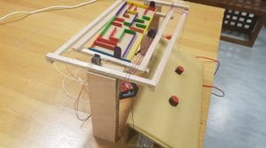
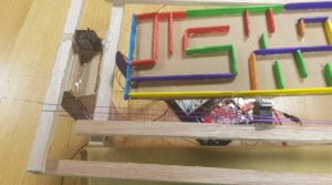
It is an tech-based imitation of a wooden labyrinth. The maze is controlled by two potentiometers and it rotates on the x and the y axes.
BEHAVIOR:
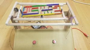
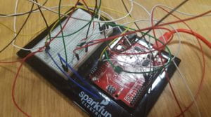
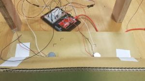
The maze is composed of popsicle sticks and a cardboard. It is placed in a frame which has a servo that rotates the board on the x-axis. Then, there is a larger frame which contains the inner frame and rotates its contents (the maze + the inner frame) on the y axis. The two servos are connected to a arduino board which takes values of two potentiometers and maps it to the angles that the servos can rotate to.
As such, when the two red knobs are used, the servos rotate the maze as needed to get the steel ball from one end to the other.
My project meets all the requirements of this midterm project as I am working with two inputs and two outputs. I also have some algorithmic processing in my code as it I take the input values which range from 0 to 1023 and map it to 0 to 50 (x-axis) and 0 to 20 (y-axis). (These values were determined through testing. As a result, the maze does not rotate all the way to 180 degrees but only as much as needed to move the ball.). Moreover, to eliminate any delayed response I used the milis() function.
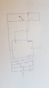
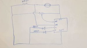
SCHEMATIC:
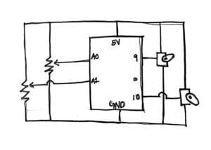
PROGRAM:
// constants won't change. Used here to set a pin number:
const int ledPin =  LED_BUILTIN;// the number of the LED pin
#include

Servo innerServo;  // create servo object to control a servo
Servo outerServo;  // create servo object to control a servo
int innerFrame = 0;  // analog pin used to connect the potentiometer
int outerFrame = 1;  // analog pin used to connect the potentiometer
int inner;    // variable to read the value from the analog pin
int outer;

unsigned long previousMillis = 0;        // will store last time the servo was updated

// constants won't change:
const long interval = 5;           // interval at which to blink (milliseconds)

void setup() {
  // set the digital pin as output:
  Serial.begin(9600);
  innerServo.attach(9);  // attaches the servo on pin 9 to the servo object
  outerServo.attach(10);  // attaches the servo on pin 9 to the servo object
}

void loop() {
  unsigned long currentMillis = millis();

  if (currentMillis - previousMillis >= interval) {
    // save the last time you blinked the LED
    previousMillis = currentMillis;
    inner = analogRead(innerFrame); // reads the value of the potentiometer (value between 0 and 1023)
    outer = analogRead(outerFrame); // reads the value of the potentiometer (value between 0 and 1023)

    inner = map(inner, 0, 1023, 0, 50);     // scale it to use it with the servo (value between 0 and 180)
    outer = map(outer, 0, 1023, 0, 20);     // scale it to use it with the servo (value between 0 and 180)
    Serial.print("inner");

    Serial.print(inner);
    Serial.print(", outer");

    Serial.println(outer);
    innerServo.write(inner);                  // sets the servo position according to the scaled value
    outerServo.write(outer);
  }
}
PROBLEMS:
I miscalculated the position of the maze within the inner frame. The maze is not centered because some space is required to fix the servo on the inside of the inner frame. As a result the center of gravity is not at the center. As such, when I was placing the entire thing inside the outer frame, it kept rotating to the side. Therefore, I used a stretchy nylon purple string to hold the frame up. I could have avoided this if I had measured the size of the servo before hand and included that in my measurements.
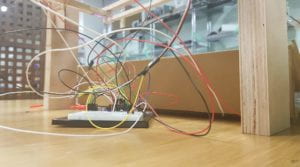
As Michael pointed out, my final prototype has three pieces (the maze, the control panel and the arduino board) instead of being a put-together whole. Perhaps if I had used a container of some sort or a wooden board to place my breadboard and arduino, my project would not be in “pieces”.
LESSONS LEARNED:
This is my first project this semester in which I used wood for the structure. Thanks to the tool training I was able to use the hand saw and the glue gun. I also understood the importance of incremental testing. Because I religiously applied this in my process, any issues that came up were resolved on a step by step basis and I never ended up in a problem-accumulated crisis.
GALLERY: