Link to documentation for the musical instrument assignment on Lucy’s blog:
Author Archives: Chunxiao Wang
Week 7 Reading Responses
For Physical Computing’s Greatest Hits (and Misses):
This article provides various forms of physical computing including the ones as obvious as motion detectors to the less obvious ones like attention detector or tilt sensor.
I do feel like to build a good physical computing device, we need to provide tactile feedback and promote structured interaction.
Tactile feedback not only provides people with limited vision better accessibility of certain functions, but is also very critical as it gives the user a deceptive sense of interacting with not the screen and device but the actual thing that the device is trying to simulation ( a book, an instrument etc..).
Structured interaction is also important because personally I would like the interactive devices to have clear instruction on how I’m suppose to operate.Otherwise I might be wasting time on trying to figure out the right way to use it or not realizing some important features.
For Make Interactive Art: Set the Stage, Then Shut Up and Listen:
This article elaborates on what we want to achieve by giving clear instructions for the users when designing an interactive device.
I think what I take from the article is that I should focus on how the user will perceive the device without me as the designer explaining it to him or her. Sometimes what we as designers think as intuitive is not so much to a first-time users. In order to test and possibly improve that, we’ll need to conduct a lot of user experiments before we commission.
Also it brings to me an interesting point that we should build a project that’s like a play where the audience are part of the story. We can use the IM projects to express ideas and emotionally affect the audience just like a theatre play can do. This might be even more effective for certain purposes (educational, awareness raising etc.) since it include the participation of the audience.
Midterm Project – moving vehicle with obstacle detection
The concept of my mid-term project is a “autonomous” vehicle with obstacle detection.
Picture with descriptions:
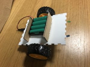
On the surface, it has a battery case holder ( two piece of cardboard glued to the acrylic board), the battery case, two wheels and two LEDs.
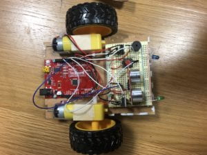
From below, the arduino board is fixed to the acrylic board by 4 nails. The solder-less breadboard is sticked to the front panel. On the breadboard, there is a distance sensor, a buzzer and a push button. The two motors controlling the wheels are glued to the side of the panel.
Behavior and gifs:
The vehicle has 4 modes:
Mode 0 – Power Off; LEDs are dimmed
Mode 1 – Gentle; LEDs are flashing
Mode 2 – autonomous; LEDs are on the whole time
Mode 3 – Ice- cream Van; one of the LEDs is on each time with the buzzer playing the tone of “Mary had a little lamb”
The modes are switched by the push button and indicated by LEDs.
In mode 1 & 2, the vehicle will keep going forward until it detects an obstacle.
The vehicle will stop when detecting obstacles under gentle mode:

The vehicle will keep turning left until the route is clear under autonomous mode:

Under ice-cream Van mode, the vehicle will keep moving forward until an obstacle (a customer) is detected. Meanwhile, it will keep playing an ice-cream van tone. ( for which I choose “Mary Had a Little Lamb”)
Problems :
The problems I have are mainly hardware constraints that I haven’t solved.
- It is very hard to make the vehicle go in a straight line (two motors have to operate exactly the same way) due to the inconsistence of the motors.
- Ideally the vehicle should move in a straight line, but after adding the tone() function for the buzzer to play the tone, the behavior of the motors are hard to coordinate. (One of the motors always stops before the other, making the vehicle to move at an angle) At first I thought I can solve this by adjusting the code but nothing works after many trials. I guess this might be due to hardware constraints (like the two motors and the buzzer might not be able to operate at the same time).
- I couldn’t figure out why the vehicle tend to suddenly terminate and restart under ice-cream van mode (which is the reason why I don’t include gif for that mode) until Micheal pointed out in class that it might due to shortage of power which lead to the restarting of Arduino. This might be solved by adding extra power (the 4 batteries I used are all 1.2-Volt batteries which might be not enough).
Lessons learned:
Since most of the problems I faced are hardware issues, I learned that I should know more about the features of the hardware pieces before I use them in my project (i.e. use more consistent motors & stronger power input).
Also I feel like the acrylic board which I choose to be the main frame of the vehicle is too small in size and become a big constraint for me to add any other features to the vehicle. Next time I’ll be more thoughtful about the size of the project in the very beginning since it is rather hard to change after most components are already mounted.
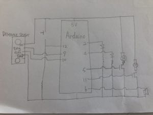
Below are the schematics for my project:
(1 Distance Sensor, 1 push button and 1 10k-ohm resistor on the left; 2 LEDs, 2 330-ohm resistors, 2 transistors, 2 motors and 1 buzzer on the right.)
(The pin names on the distance sensor are: (top to bottom) VCC, trig, echo, GND)
Below is the source code for my project:
#include "pitches.h"
// defines pins numbers
int blueLED = 2;
int greenLED = 4;
int Lmotor = 5;
int buzzer = 6;
const int trigPin = 9;
const int echoPin = 10;
int Rmotor = 11;
int modeSwitch = 12;
long duration;
int distance;
int thisNote = 0;
int blue = 0;

int mode = 0;
//modes = {0:power off,1:forward/stop, 2:icecream van, 3:forward/leftturn}
int switchVal;
int reading = false;


//melody and tempo for mary had a little lamb
int melody[] =
{ NOTE_E7, NOTE_D7, NOTE_C7, NOTE_D7, NOTE_E7, NOTE_E7, NOTE_E7,
  NOTE_D7, NOTE_D7, NOTE_D7, NOTE_E7, NOTE_G7, NOTE_G7,
  NOTE_E7, NOTE_D7, NOTE_C7, NOTE_D7, NOTE_E7, NOTE_E7, NOTE_E7,
  NOTE_E7, NOTE_D7, NOTE_D7, NOTE_E7, NOTE_D7, NOTE_C7
};


int noteDuration[] = {375, 125, 250, 250, 250, 250, 500,
                      250, 250, 500, 250, 250, 500,
                      375, 125, 250, 250, 250, 250, 250,
                      250, 250, 250, 250, 250, 1000
                     };

// the setup function runs once when you press reset or power the board
void setup() {
  // initialize digital pin LED_BUILTIN as an output.
  pinMode(Rmotor, OUTPUT);
  pinMode(Lmotor, OUTPUT);
  pinMode(trigPin, OUTPUT); // Sets the trigPin as an Output
  pinMode(echoPin, INPUT); // Sets the echoPin as an Input
  pinMode(blueLED, OUTPUT);
  pinMode(greenLED, OUTPUT);
  Serial.begin(9600);
}

// the loop function runs over and over again forever
void loop() {

  getDistance();

  switchVal = digitalRead(modeSwitch);
  //if statements to change the modes according to the push button
  if (switchVal) {
    reading = true;
  }
  Serial.println(switchVal);
  if (reading && !switchVal) {
    reading = false;
    mode = (mode + 1) % 4;
  }
  // mode 0, everything powered off
  if (mode ==0){
    digitalWrite(Rmotor, LOW);
    digitalWrite(Lmotor,LOW);
    digitalWrite(greenLED, LOW);
    digitalWrite(blueLED, LOW);
  }
  // mode 3, ice cream car (car move with a tone, stop if obstacle detected)
  else if (mode == 3) {
    tone(buzzer, melody[thisNote], noteDuration[thisNote]*0.8);
    int pause = noteDuration[thisNote] * 2.5;
    delay(pause);
    thisNote = (thisNote + 1) % 26;
    // if statements to turn one of the leds up
    if (blue) {
      digitalWrite(greenLED, LOW);
      digitalWrite(blueLED, HIGH);
    }
    else {
      digitalWrite(blueLED, LOW);
      digitalWrite(greenLED, HIGH);
    }
    blue = !blue;
    //stop if obstacle detected
    if (distance > 15) {

      analogWrite(Rmotor, 100);
      analogWrite(Lmotor, 100);
      delay(250);
      analogWrite(Rmotor, 110);
      delay(250);
    }
    else {
      digitalWrite(Rmotor, LOW);
      digitalWrite(Lmotor, LOW);
      delay(500);
    }
  }

    //mode 1, gentle - stop when obstacle detected
   else if (mode == 1){
      digitalWrite(greenLED, HIGH);
    digitalWrite(blueLED, HIGH);
    delay(100);
    digitalWrite(greenLED, LOW);
    digitalWrite(blueLED, LOW);
    delay(100);
    if (distance > 10) {
      analogWrite(Rmotor, 80);
      analogWrite(Lmotor, 100);
      delay(500);
    }
    else {
        digitalWrite(Rmotor, LOW);
      digitalWrite(Lmotor, LOW);
      delay(500);
    }}
    //mode 2, autonomous - turn when obstacle detected and keep going
    else{
    digitalWrite(greenLED, HIGH);
    digitalWrite(blueLED, HIGH);
    delay(100);
      if (distance > 15) {
      analogWrite(Rmotor, 80);
      analogWrite(Lmotor, 100);
      delay(500);
    }
    else {
        digitalWrite(Rmotor, LOW);
     //making a left turn
      delay(500);
    }}

  }


void getDistance() {
  // Clears the trigPin
  digitalWrite(trigPin, LOW);
  delayMicroseconds(2);
  // Sets the trigPin on HIGH state for 10 micro seconds
  digitalWrite(trigPin, HIGH);
  delayMicroseconds(10);
  digitalWrite(trigPin, LOW);
  // Reads the echoPin, returns the sound wave travel time in microseconds
  duration = pulseIn(echoPin, HIGH);
  // Calculating the distance
  distance = duration * 0.034 / 2;
  Serial.print("Distance: ");
  Serial.println(distance);
}
void straightline() {
  analogWrite(Rmotor, 90);
  analogWrite(Lmotor, 100);
  delay(500);                       // wait for a second
}
The code for distance sensor is taken from:https://howtomechatronics.com/tutorials/arduino/ultrasonic-sensor-hc-sr04/
Week 4 Reading Responses (Bret Victor)
Victor’s rant touches upon how modern technology, both the existing and proposed ones, is only utilizing very limited human capability — touching and sliding fingers on a glassy surface and vision.Even the proposed ones are only incrementing more elaborate visuals on lighter, less glassy surfaces but the principle is about the same. ( The video is unavailable so I’m only based on the images provided.)
The fact that human body has so much capabilities while the “technology” that are in use recently deploys so little of them is thought-provoking.
During the last summer I did a research that’s related to VR and AR applications. In fact, these applications are basically converting other glasses equipments (i.e. glasses, front-glass of a car) into a display screen. Nowadays I already feel like we do too much on screens – we play games/ watch videos during leisure time and take notes/ use productivity softwares during working time.And VR and AR, the pioneers of front-end technology, are still trying to make more uses of different type of screens.
I have been wearing glasses since the age of 8 and I always find it pitiful that my view of the world surrounding me has to be through lenses. But modern technology factually detach us from the physical world even more. The idea that technology should rethink about human body’s capability and not restricted to fingers sliding on a glassy surface is definitely worth considering. I wish that in the future we can have technology that will make use of more functionalities of our body and enable us do things we wouldn’t have imagined.
Week 3 Reading Responses
Response to Crawford:
In the reading, Crawford defines interactivity as a process where two actors listen, think, and speak. This definition is interesting to me as I use to think interactivity needs only the speaking(acting) from one party while the other can just listen and think . For example, I use to consider any media interactive, like a film, because they all somehow deal with the audience’s five senses (now that I think of it, the engaging with senses like listening and sight only has little connection with interactivity). The reading make me realize the importance of thinking and decision for all parties to exist in interactivity. I can’t say that process can’t be considered interactive if one participant lack a deep level thinking, but it is truly a more interesting subject of study if all parties perform a thorough thinking process before they decide how to react.
Response to Norman:
The second reading talks about some fundamental principles for interactive design which I find interesting. ( By the way, many of the example shown in this reading contrast the definition from Crawford’s reading as many devices mentioned here lack deep level thinking or any thinking at all.)
As a CS major, whenever I approach a problem, I tend to use what I call a “back-end” approach – -like the coding, basic logic for coding etc. This reading make me think that the “front-end” part is also very crucial to the success of any human-centered interactive product. The design of front-end (like user interface of software, web page. ..etc) is also a combination of art and science. I tend to focus mainly on the “affordances” as trying to realize all the functions of a device and lay them blindly on the interface, much alike to the app designer example in the reading.
Signifiers and mapping are actually very important to user experience. I as a user will realize and appreciate the thoughts put into any good design very soon after I start to use them. These terms shed light to my consideration for any future design I’m going to make and I’ll definitely revisit them later in my career.
Week 2&3 Circuit with 4 LEDs and 3 Digital/Analog Inputs
Week 2:
For my circuit w/ LEDs and sensors, I first draw the following schematics:
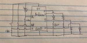
I have 3 inputs where 2 are analog inputs(potentiometer and light sensor) and the other is a digital input (the push button switch). They are connected to Arduino pins A0, A1, 2, respectively. I also have 4 LEDs as both digital and analog outputs, and they are connected to Arduino pins 3,6,9,10 ( the pins all allow analog outputs). I also connect 10K-ohm resistors to the switch and the light sensor and 330K-ohm resistors to each LED to make sure they all get appropriate amount of volts.
The Arduino program I write is as following:
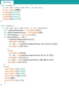
Basically, I want the potentiometer to control the first two LEDs. As I rotate the top part of the potentiometer, the LED at pin 10 will go from dim to bright then turned off and then the LED at pin 9 will go from dim to bright and vice versa. The light sensor should control the LED at pin 6. The brighter the environment is, the dimmer the LED should go.
Finally, I want the switch to control all 4 LEDs, where all 4 will be turned to full brightness when the button is pressed and go back to their prior state after 200 ms.
The following gif demonstrates the behavior of the circuit as described above:

Week 3 update:
This week I continued with the same schematics as drawn above. In addition to the behavior described above, I also include a “write_enable” variable to store the state of the device. Its behavior is reflected by the blue LED. When w_e is false, the device is put to “rest” stage and all LEDs other than the blue one are off and not controllable. Once the switch is pressed, the blue LED will blink 4 times and all other LEDs are back to “live”. Similarly, the other 3 will go back to “rest”mode if the switch is then pressed again.
The above behavior is demonstrated in the following gif:

Problem:
This week for some reason the reading from my potentiometer range only from [497,1023] instead of [0,1023]. I changed the mapping in my original code accordingly but yet to figure out the cause for that.
Updated full code:
void setup() {
  // put your setup code here, to run once:
  Serial.begin(9600);
  pinMode(3, OUTPUT);
  pinMode(6, OUTPUT);
  pinMode(9, OUTPUT);
  pinMode(10, OUTPUT);
}
int write_enable = false;
void loop() {
  // put your main code here, to run repeatedly:
  int lightsensorValue = analogRead(A1);
  int potentiometerValue = analogRead(A0);
  int switchValue = digitalRead(2);
  int mid = (1023 - 497) / 2;

  if (switchValue == 0 && write_enable) {
    if (potentiometerValue > 497 + mid) {
      analogWrite(9, 0);
      int var = map(potentiometerValue, 497 + mid, 1023, 0, 255);
      analogWrite(10, var);
    }
    else {
      analogWrite(10, 0);
      int var = map(potentiometerValue, 497, 497 + mid, 0, 255);
      analogWrite(9, var);
    }
    int var2 = map(lightsensorValue, 0, 650, 20, 150);
    analogWrite(6, var2);
  }
  //set w_e to false,put device back to sleep
  else if (switchValue == 1 && write_enable) {
    for (int count = 4; count > 0; count--) {
      digitalWrite(3, HIGH);
      delay(100);
      digitalWrite(3, LOW);
      delay(100);
    }
    digitalWrite(6, LOW);
    digitalWrite(9, LOW);
    digitalWrite(10, LOW);
    write_enable = false;
  }
  //set w_e to true, wake up device again
  else if (switchValue == 1 && !write_enable) {
    for (int count = 4; count > 0; count--) {
      digitalWrite(3, HIGH);
      delay(100);
      digitalWrite(3, LOW);
      delay(100);
    }
    digitalWrite(6, HIGH);
    digitalWrite(9, HIGH);
    digitalWrite(10, HIGH);
    delay(200);
    digitalWrite(6, LOW);
    digitalWrite(9, LOW);
    digitalWrite(10, LOW);
    write_enable = true;
  }
  // defalut stage
  else {
    digitalWrite(3, HIGH);
  }
}
Switch with straws and salt water
For my switch that doesn’t use hands, I come up with the idea to make use of electrolyte solution as the conductor in the switch. The reason for that is because it is each to move liquid from one place to another inside my switch by simply blowing them.
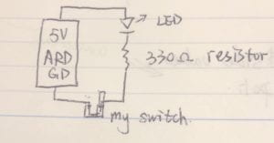
First, I construct a simple open circuit as drawn in the diagram — an Arduino unit connected to the USE port on my laptop as the power source, an LED, a resistor, wires connecting them and two open end wires to be connected to my switch.
The electrolyte I choose to use for my switch is the one with the most accessibility — salt (NaCl). I put some salt that I take from D2 into a can with water and shake it well to help the dissolution.I want to build a device that’s open on both end and easy for me toblow from one end. And I use some straws to build such a device.First, I insert one long straw into one short straw. The long straw is for the excess salt water to be held and the short straw is for a “blowing straw” to be inserted. I put a certain amount of salt water into the device that has the height of the diameter of the straws (which doesn’t go up to the vertical part of the device).Next, I insert the two dangling wires into the two open ends of the device. I want the default state of my switch to be breaking the connection so I put the wire in the long straw slightly higher than the surface of the solution. The last step of building is to add a short “blowing straw” onto the short straw to make blowing easier.
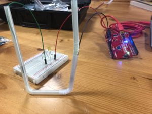
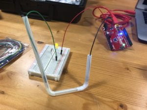
To turn on the switch, gently blow from the “blowing straw” to make the two wires both in contact with the salt water.

The default state (broken connection) can be changed to connection simply by adjusting the position of the wire inside the long straw(make it in contact with the salt water). In this case, the connection can be broken by blowing harder to make the other wire no longer in contact with salt water.
Interaction on campus – Inside an elevator
Every day, most of us take the elevator at least once on the campus. Usually we’ll meet someone in the elevator after we get in and before we go out. Interactions among people during an elevator ride are unique as they are trapped in the same closed “box” with almost nothing to distract them from noticing each other. If we meet some one we know and get along with, we might easily exchange some simple greetings the same way as if we meet on the street. Problem solved, and live is easy. More likely, though, we’ll meet some complete strangers in the elevator, and that’s when things get interesting.
People tend to look at their phones to avoid eye contact or any form of interactions with strangers in the elevator, despite the fact that phones usually have poor signal inside it. The silence is usually awkward but understandable. Since we usually take the elevator to go up about 2 to 3 floors, the duration of the ride is about a minute or two, which hardly supports any effective conversation with strangers. When I do converse with people that I don’t know before in an elevator, more than often we’ll stop after exchanging basic personal info like name, major, year…etc. And I’ll probably forget what we exchange if I don’t re-encounter the same person in a day or two. In pragmatists’ eyes this kind of short conversation might be hardly useful. But it’s also possible that the first short conversation you exchange with a stranger might be the start of a profound friendship, as we are very likely to bump into the same person again within our not-so-huge campus. Even not so, a conversation inside an elevator might just delight one another as most of us want to be social. In that sense, a short conversation in an elevator can be somewhat “useful”.
In conclusion, it is okay to look at phones in an elevator, but that might deny you the chance of experiencing something simple but joyful.
