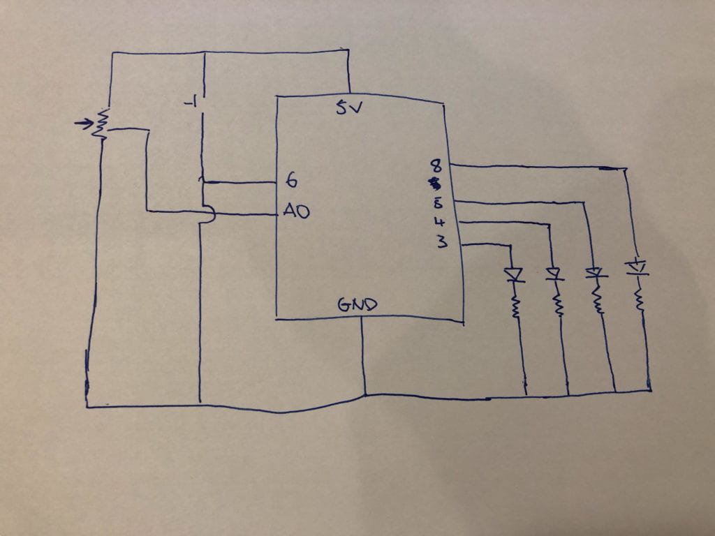
For this lab, we were tasked to utilize an analog sensor and a digital sensor to control LED’s. I used the design I used in the previous lab and added a digital sensor (a button). The one before used an analog sensor (the potentiometer) to control the LED’s. By turning the potentiometer, the LED’s would light up. The amount you turn changes how the LED’s light up.
This project uses an additional button and LED. It works by taking an input from the button (either a 1 or a 0). If the value obtained from the analog sensor is 0 and the value obtained from the digital sensor is 1, all three LED lights light up simultaneously. The fourth LED is always turned on when the button is not pressed (returns a 0). Once the button is pressed (returns a 1), the fourth LED is turned off. This applies to the various stages of the 3 LED lights (these correspond to the previous project).
The schematic for the project is provided below (I apologize for my poor drawing skills):
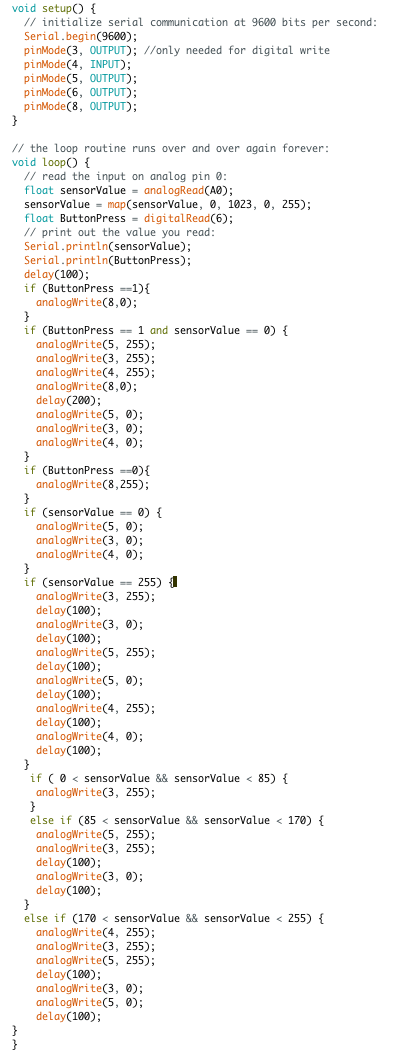
I had no real issues setting up the circuit or writing the code. However, I did encounter a “feature” that I did not intend. When I turn the potentiometer to its max and press the button, it is supposed to blink the first three LED lights and turn off the fourth. However, that’s not the case: the three LED lights revert back to as if the analog data is between 170 and 255 (that is, 2 blinking LED’s with one on continuously). The fourth LED does turn off though. I am still unsure how to resolve this issue.
I have attached a screenshot of my code:
