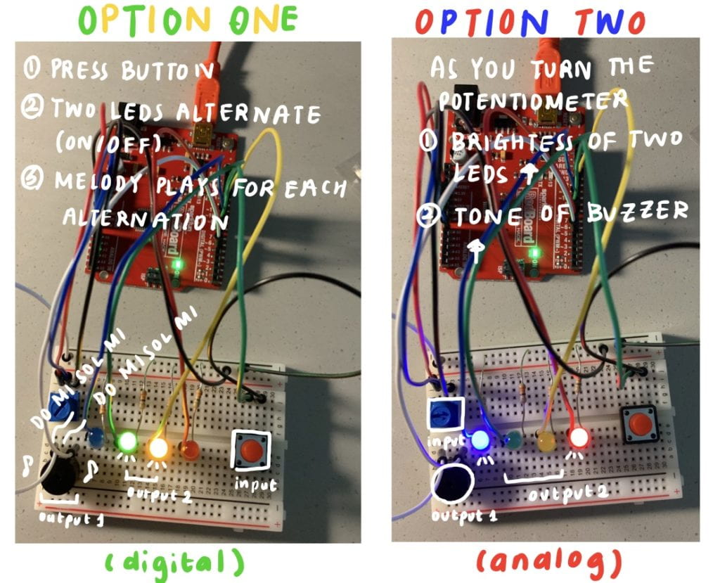
For this assignment, I created a program that could run two different functions according to the type of sensor used.
 The first option was using the digital button as the input. When the button is pressed, the green and yellow LEDs alternate with different tones from the buzzer. This was achieved through the use of the delay function with the duration of 300ms. The melody continues to loop as long as the button is pressed.
One challenge I had with the button was that when it was not pressed, the serial print values of the button was unstable, showing alternating values of 0s and 1s. This led to the LED being slightly on although the button was not pressed. To solve this issue, instead of using “pinMode(button,INPUT)”, I found a solution online that suggested me to use “pinMode(button,INPUT_PULLUP)”.
This is the video showing the running program for option 1 using the digital button. (Turn on the volume to hear the melody!)
Option 1 – Digital Button / Melody
The second option was using the analog potentiometer as the input. When the potentiometer was turned from low to max, the 8 sounds (do, re, mi, fa, sol, la, ti, do) was played for each designated interval. I divided the sounds through 125 (ex. tone(buzzer,125) , tone(buzzer,250),etc). I came to this number through diving 1023 (max number of potentiometer) by 8. Also, the potentiometer was used to control the brightness of the blue and red LEDs.
This is the video for option 2. (Turn on the volume to hear the sound)
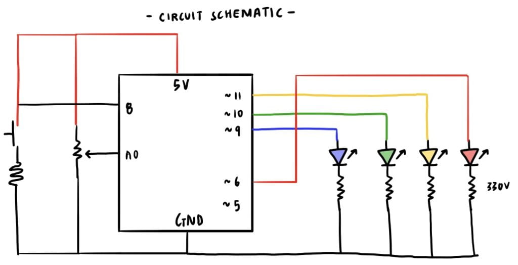
The circuit schematic of the project is as below:
The code written on the Arduino software is
//INPUTS
int pot = A0;
int button = 8;
int buzzer = 5;//OUTPUTS
int led_blue = 9; //blue
int led_red = 6; //red
int led_yellow = 11; // yellow
int led_green = 10; //green//VALUES
int pot_value = 0; // value read from the pot
int button_state = LOW;//SETUP
void setup() {
Serial.begin(9600); //initialize serial communications at 9600 bpspinMode(button, INPUT_PULLUP); //button digital input
pinMode(led_blue, OUTPUT); //controlled with analog sensor
pinMode(led_green, OUTPUT); //controlled with digital sensor
pinMode(led_yellow, OUTPUT);
pinMode(led_red, OUTPUT);
}//LOOP
void loop() {//ANALOG
//read the analog in value
pot_value = analogRead(pot);//print the values in serial monitor
//Serial.println(pot_value);//LED (RED AND BLUE)
//adjust brightness of led according to analog input of potentiometer
analogWrite(led_blue, pot_value / 4);
analogWrite(led_red, pot_value / 4);//BUZZER
if (pot_value < 25) {
noTone(buzzer);
}//do
else if (pot_value < 125) {
tone(buzzer, 262);
}//re
else if (pot_value < 250) {
tone(buzzer, 294);
}//mi
else if (pot_value < 375) {
tone(buzzer, 330);
}//fa
else if (pot_value < 500) {
tone(buzzer, 349);
}//sol
else if (pot_value < 625) {
tone(buzzer, 392);
}//la
else if (pot_value < 750) {
tone(buzzer, 440);
}//ti
else if (pot_value < 875) {
tone(buzzer, 494);
}//do
else if (pot_value < 1100) {
tone(buzzer, 524);
}//read switch state
button_state = digitalRead(button);if (button_state == 0) {
//DO
tone(buzzer,262);
digitalWrite(led_green, HIGH);
delay(300);//MI
tone(buzzer,330);
digitalWrite(led_yellow, HIGH);
delay(300);//SOL
tone(buzzer,392);
digitalWrite(led_green, LOW);
delay(300);//MI
tone(buzzer,330);
digitalWrite(led_yellow, LOW);
delay(300);}
else {
digitalWrite(led_green, LOW);
digitalWrite(led_yellow, LOW);}
}


There is an error in your schematic, and if your circuit was an implementation of the schematic, that was the reason you needed to set the mode to “PULLUP”. Perhaps now you can spot the error, but let me know if you don’t and I’ll show you.