All I remembered for this project was that we were tasked to mess with LED lights. I think I’m on the right track here.
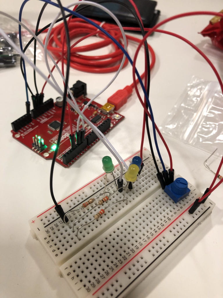
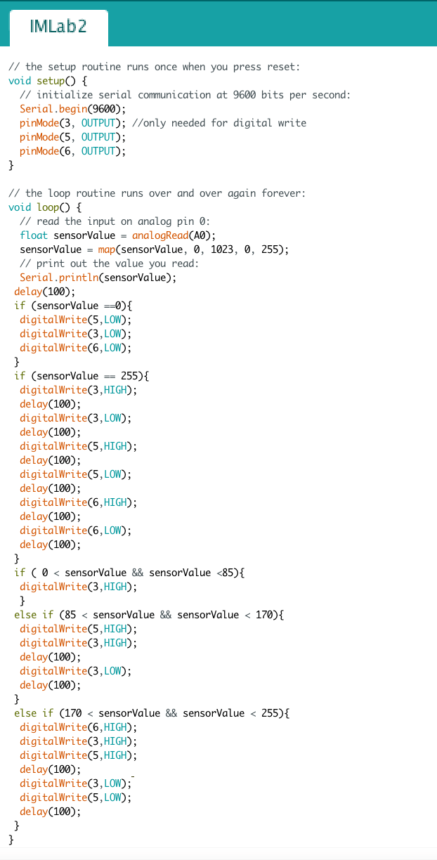
For this project, I used three LED lights and a potentiometer (I swear I can never pronounce this word on the first try). The potentiometer is the analog input. The values for this range from 0 to 1023. However, the LED lights only range from 0 to 255. Therefore, a map is needed. When you the potentiometer is at 0, no lights light up. When the potentiometer is is moved past zero but less than 1/3 of the way, one LED lights up. When the range is inbetween 1/3 and 2/3, the second LED turns on and the first LED light starts blinking. Once it reaches past 2/3 of the potentiometer, the third LED turns on and the other two lights start blinking. Lastly, at the maximum limit of the potentiometer, all three lights start blinking.

This is the breadboard with the LED lights
I have also attached a screenshot of the code for reference.

This is the code for my LED project.
