
Assignment 2:
For this second assignment, I opted into making a simple traffic light. Started with coming up with a solid idea on how I’m going to make it and decided on using three LEDs, green, yellow and red, a button and a light sensor. The light sensor recorded the light. The idea was that if an object were close (an imaginary car, for example) the amount of light hitting the sensor would decrease and make the green LED to go on. It’s there to turn the traffic light green if there we’re supposed cars driving in. On the other hand, the button served as the pedestrians “wait” button, where they click it to make the traffic light go red.
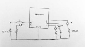
With that idea in mind, I started by making a schematic:
Next up, I built that on the Arduino:
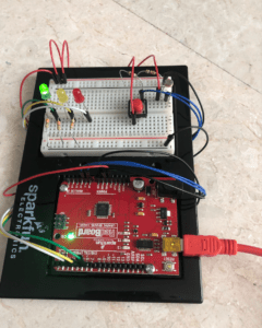
At first, I had lots of wires going from the resistor to the ground lane, but then I opted to remove that and try just using the resistors alone directly connecting the LED to the ground lane, and it worked. Another thing I faced was the button was giving me random readings at times but it ended up being that I didn’t connect it to 5 volts.
After having the circuit done and testing each input and output to see if they’re working, I wrote the code while referencing code written in the Arduino examples, like the analog button and blinking, we did in class to help with getting the syntax right as well as to know what to write to get all I/Os to work.
This is the code I ended up with:
//variable that are constant, setting the pin numbers
const int buttonPin = 14; //the push button pin
const int lightSensor = 15; // light sensor
const int greenLED = 6; //led pins
const int yellowLED = 5;
const int redLED = 3;
int buttonState = 0; //button status
int sensorState = 0;
void setup() {
  Serial.begin(9600);
  //OUTPUTS
  pinMode(greenLED, OUTPUT);
  pinMode(yellowLED, OUTPUT);
  pinMode(redLED, OUTPUT);
  //INPUTS
  pinMode(buttonPin, INPUT);
  pinMode(lightSensor, INPUT);
  digitalWrite(greenLED, HIGH);
}

void loop() {

  int buttonState = digitalRead (buttonPin); //state of the button being from an analog input
  int sensorState = analogRead (lightSensor); //state of light sensor

  if (buttonState > 0){ //if the state is high/ if the button is pressed
    digitalWrite(redLED, LOW); //turn of red LED if its on
    digitalWrite(greenLED, HIGH); // turn on green
    delay(1000);
    digitalWrite(greenLED, LOW); //turn off green LED
    digitalWrite(yellowLED, HIGH); //turn on yellow LED
    delay(500); //pause for a bit
    digitalWrite(yellowLED, LOW); //turn of yellow LED
    digitalWrite(redLED, HIGH); //turn on red LED


  }

  if (sensorState < 600){ //if the sensor gets an input more than 0
    digitalWrite(redLED, LOW);
    digitalWrite(greenLED, HIGH);

  }
}
I’ve had to edit the light sensor’s code depending on the place I was in because it wasn’t consistent in different places.
The final result:
Assignment 3:
I’ve already explained the concept above in assignment 2. I made a few changes for this one, instead of a light sensor I used a distance sensor. I also added twice the amount of LEDs for aesthetics.
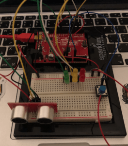
The digital input is from the distance sensor while the analog input is from the button. As for the LEDs, the digital inputs are the red and green LEDs while the yellow ones are the analog. When the LED’s are on, the red and green just go on and off and the yellow blinks.
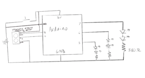
Schematic:
I used code from https://howtomechatronics.com/tutorials/arduino/ultrasonic-sensor-hc-sr04/ to understand and get the UV distance sensor to work.
Here’s the final code:
const int trigPin = 11;
const int echoPin = 13;
const int greenLED = 6;
const int yellowLED = 5;
const int redLED = 3;
const int buttonPin = 14;
long duration;
int distance;

void setup() {
  pinMode(trigPin, OUTPUT); // Sets the trigPin as an Output
  pinMode(greenLED, OUTPUT);
  pinMode(yellowLED, OUTPUT);
  pinMode(redLED, OUTPUT);

  pinMode(buttonPin, INPUT);
  pinMode(echoPin, INPUT); // Sets the echoPin as an Input
  Serial.begin(9600); // Starts the serial communication

  digitalWrite(greenLED, HIGH);
}

void loop() {
  // Clears the trigPin
  digitalWrite(trigPin, LOW);
  delayMicroseconds(2);

  // Sets the trigPin on HIGH state for 10 micro seconds
  digitalWrite(trigPin, HIGH);
  delayMicroseconds(10);
  digitalWrite(trigPin, LOW);

  // Reads the echoPin, returns the sound wave travel time in microseconds
  duration = pulseIn(echoPin, HIGH);

  // Calculating the distance
  distance = duration * 0.034 / 2;

  Serial.print("Distance: ");
  Serial.println(distance);
  int buttonState = digitalRead (buttonPin);
  bool inMotion = false;

  if (distance < 7) { inMotion == true; digitalWrite(redLED, LOW); //delay(500); digitalWrite(greenLED, HIGH); delay(100); } if (buttonState > 0 && inMotion == false) {
    inMotion = true;
    delay(500);
    digitalWrite(redLED, LOW); //turn of red LED if its on
    digitalWrite(greenLED, LOW); //turn off green LED
    for ( int counter = 0; counter <= 2; counter++) {
      analogWrite(yellowLED, 255);
      delay(500);
      analogWrite(yellowLED, LOW);
      delay(500);
    }
    digitalWrite(redLED, HIGH);
    //analogWrite(yellowLED, 255);
    // delay(1000);
    //analogWrite(yellowLED, 0);
    //delay(1000);

  }

}
Final assignment: